
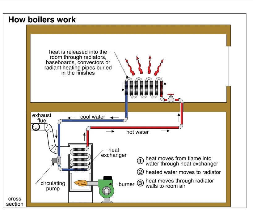
Related illustrations
 0850
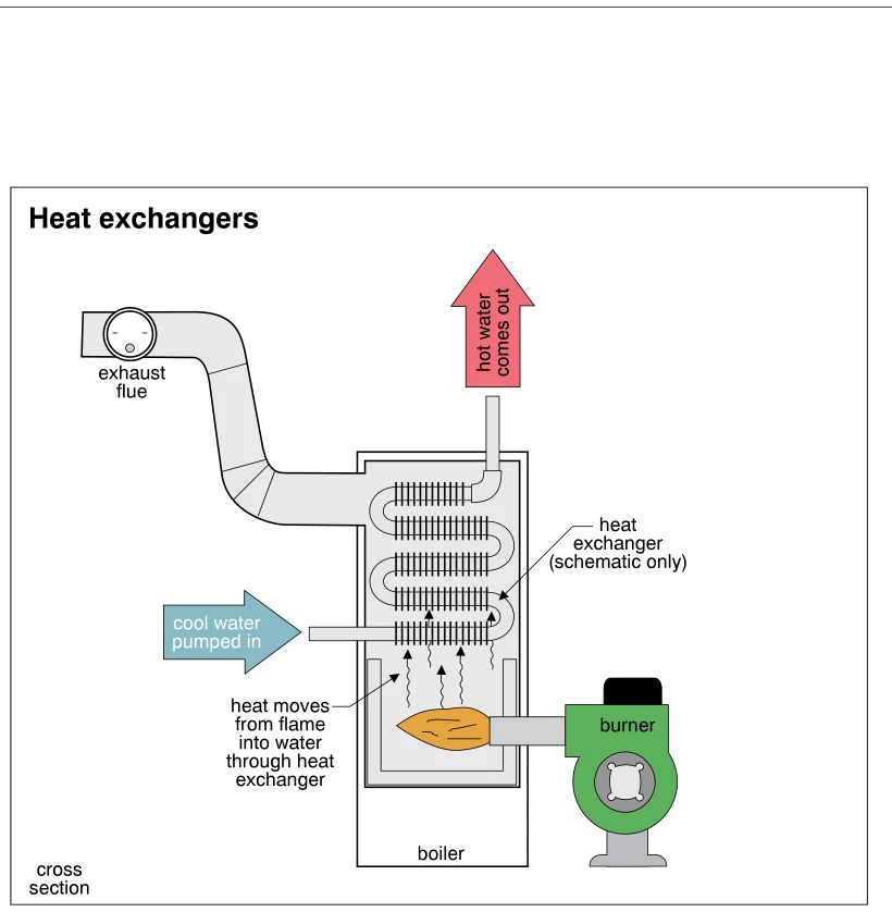
0850Heat exchangers
· p. 143
The illustration shows a schematic cross section of a hot-water boiler with a side-mounted burner firing into the lower combustion chamber. Cool water is pumped into the bottom of a serpentine, finned heat exchanger, and
 0748
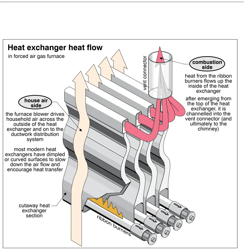
0748Heat exchanger heat flow
· p. 121
The illustration shows a cutaway of a forced-air gas furnace heat exchanger with ribbon burners beneath multiple curved exchanger sections. Pink arrows trace the combustion-side flow upward through the interiors of the s
 0851
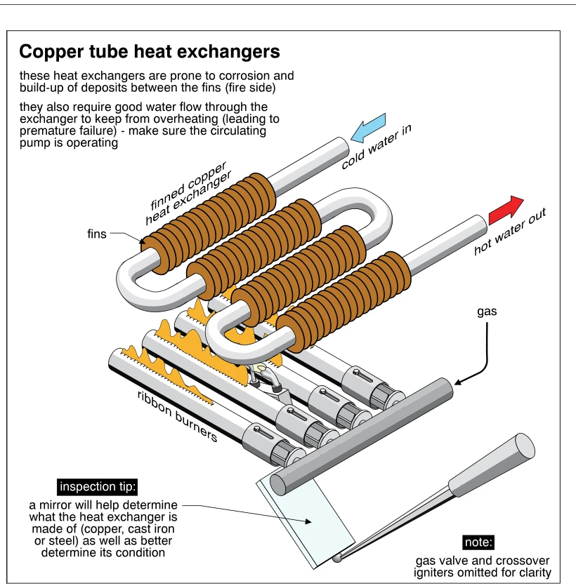
0851Copper tube heat exchangers
· p. 143
The illustration shows a serpentine finned copper heat exchanger positioned above gas-fired ribbon burners in a boiler. Arrows identify cold water entering one end and hot water leaving the other, while a gas supply feed
 1353
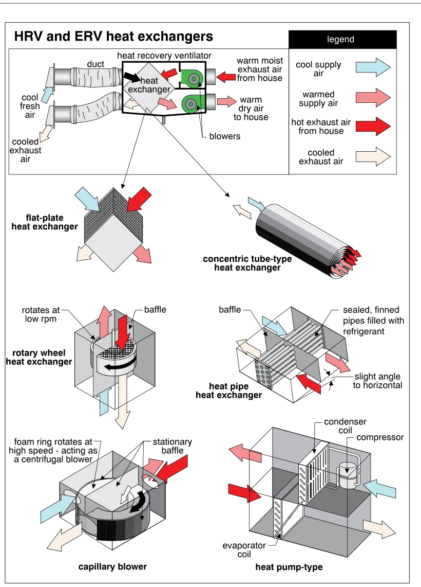
1353HRV and ERV heat exchangers
· p. 243
The illustration shows a ducted heat recovery ventilator with two blowers and a heat exchanger transferring heat from warm house exhaust air to incoming cool fresh air. Color-coded arrows distinguish cool supply air, war
 1096
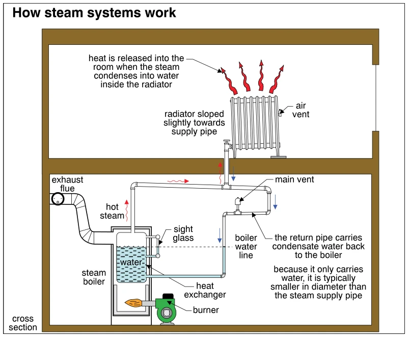
1096How steam systems work
· p. 191
A cross-sectional schematic shows a steam boiler below a room radiator, connected by steam supply and condensate return piping. A burner heats the boiler water, and red arrows trace hot steam rising to the radiator, wher
 1097
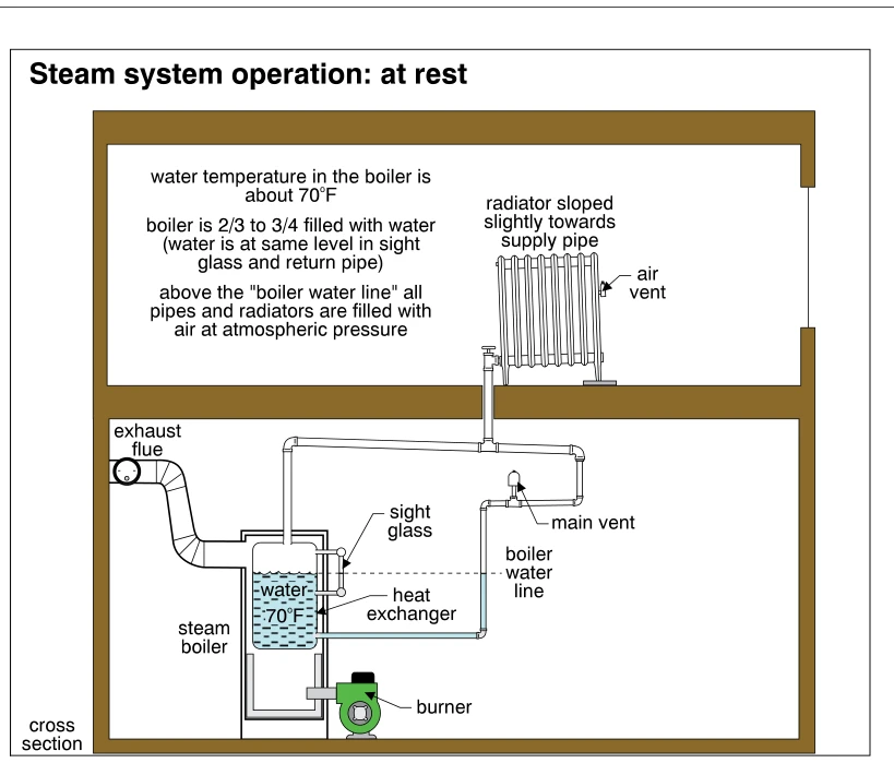
1097Steam system operation: at rest
· p. 192
A building cross section shows a steam boiler below a radiator, connected by supply and return piping. At rest, the boiler is two-thirds to three-quarters filled with water at about 70°F, with the same water level in the
 0847
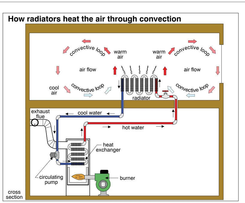
0847How radiators heat the air through convection
· p. 142
A building cross section shows a hot-water heating system with a burner and heat exchanger on the lower level connected to a radiator above. Red supply piping carries hot water to the radiator, while blue return piping c