
04Heating
449 illustrations · printed pages 109-208
Furnaces – Gas And Oil ·Introductionp. 110
 0700
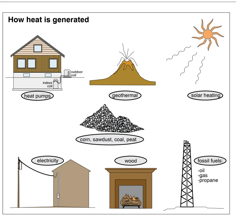
0700How heat is generated
· p. 110
The illustration presents several sources and methods of residential heating. A house with connected indoor and outdoor coils represents heat pumps, while a volcano and the sun symbolize geothermal and solar heating. Piles of fuel are labeled corn, sawdust, coal, and peat. An electrical service connected to a house represents electricity, a burning fireplace represents wood heating, and a drilling derrick represents oil, gas, and propane. This is an informational overview rather than an installation detail or a depiction of defects.
 0701
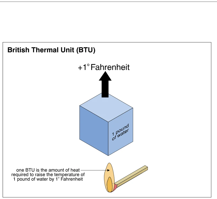
0701British Thermal Unit (BTU)
· p. 110
The illustration explains a British Thermal Unit using a blue cube representing one pound of water. An upward arrow above the cube indicates a temperature increase of 1° Fahrenheit. A burning match below the cube symbolizes heat input, with an annotation defining one BTU as the heat required to produce that temperature rise. This is a conceptual explanation of heat measurement rather than a heating-system installation detail.
 0702
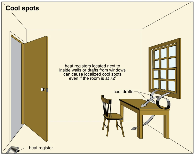
0702Cool spots
· p. 110
The illustration shows a room with a floor heat register near an open doorway on an inside wall and a window on the opposite side. A table and chair sit beside the window. Curved arrows show cool drafts moving from the window across the table and toward the floor. The annotation explains that registers located next to inside walls or drafts from windows can create localized cool spots even when the room temperature is 72°.
 0703
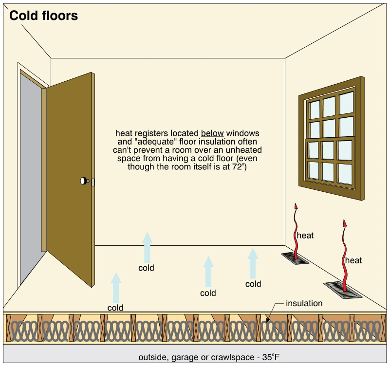
0703Cold floors
· p. 110
The illustration depicts a room with two floor heat registers along the wall beneath a window. A cutaway at the front edge shows insulation between the floor framing members above an area labeled as outside, a garage, or a crawlspace at 35°F. Red arrows indicate heat rising from the registers, while blue arrows identify cold conditions at the floor. The annotation explains that registers below windows and "adequate" floor insulation may not prevent cold floors over unheated spaces, even when the room itself is at 72°.
 0704
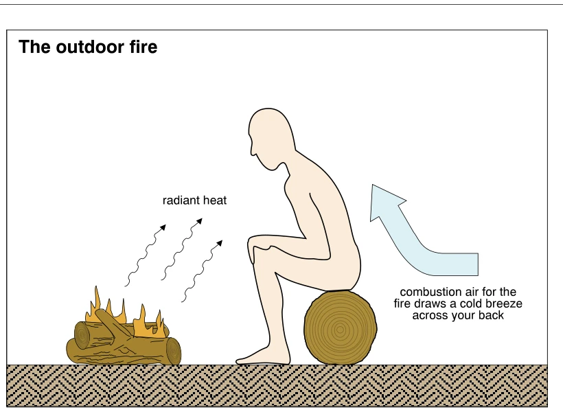
0704The outdoor fire
· p. 111
The illustration shows a person seated on a log facing an outdoor wood fire. Wavy arrows indicate radiant heat traveling from the flames toward the person. A large curved arrow behind the person represents cold air drawn toward the fire to support combustion, creating a breeze across the person's back. The diagram contrasts direct radiant warming with the cooling effect of incoming combustion air.
 0705
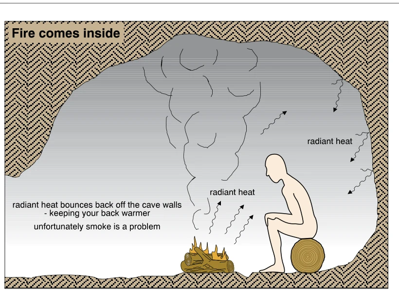
0705Fire comes inside
· p. 111
The illustration shows an open wood fire on a cave floor, with a person seated nearby on a log. Wavy arrows depict radiant heat traveling from the fire toward the person and returning from the cave walls. A large plume of smoke rises from the fire and occupies the upper cave interior. The annotations explain the warming effect of the enclosing walls while identifying smoke as a problem with bringing an open fire indoors.
 0706
0706The hole in the roof
· p. 111
The illustration shows a cave enclosure with an open wood fire on the floor and a hole in the roof above it. Smoke rises from the fire and exits through the roof opening, without a chimney. A person sits on a log beside the fire, while wavy arrows indicate radiant heat traveling from the fire and reflecting from the cave walls. The annotation explains that the roof opening improved smoke removal while retaining the benefits of radiant heating.
 0707
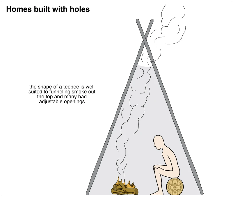
0707Homes built with holes
· p. 111
The illustration shows a cutaway of a teepee with an open wood fire at ground level and a person seated beside it on a log. The sloping sides converge toward an opening at the top, with support poles extending above the enclosure. Smoke rises from the fire through the interior and exits through the upper opening. The annotation explains that the teepee shape funnels smoke outward and that many teepees had adjustable openings, illustrating an early approach to venting combustion smoke.
 0708
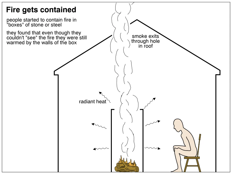
0708Fire gets contained
· p. 111
A schematic house section shows a wood fire contained between the walls of a box-like enclosure. Wavy arrows extend outward from the enclosure, illustrating radiant heat warming the occupied space and a seated person nearby. Smoke rises directly from the fire through the room and exits through an opening in the roof; no chimney or enclosed flue is shown. The annotations describe the historical use of stone or steel boxes to contain fire while allowing heat to radiate from their walls.
 0709
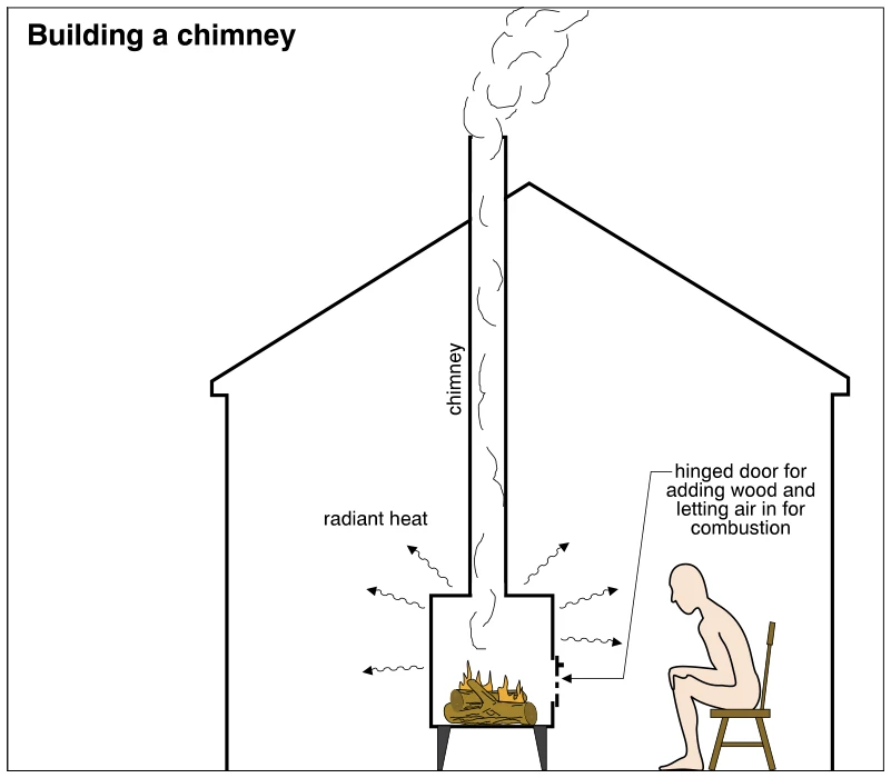
0709Building a chimney
· p. 111
A schematic house section shows a wood-burning heater connected to a vertical chimney that extends above the pitched roof. Burning logs are enclosed in the heater, with a hinged side door identified as the opening for adding wood and admitting combustion air. Wavy arrows radiate outward from the heater to illustrate radiant heat reaching the occupied room. A seated person faces the heater, while smoke rises through the chimney and exits above the roof. No construction details or specific defects are shown.
Furnaces – Gas And Oil ·Heat Transferp. 112
 0710
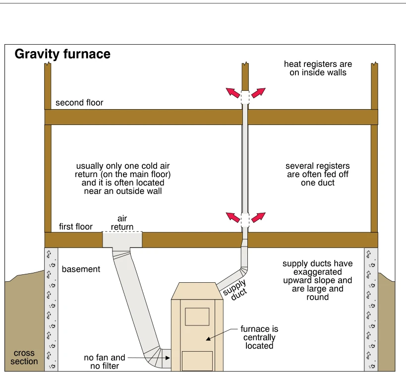
0710Gravity furnace
· p. 112
A cross section of a two-story house shows a centrally located gravity furnace in the basement. A large supply duct slopes upward from the furnace and continues through an interior wall to heat registers on both floors, with arrows indicating warm air entering the rooms. A single main-floor cold-air return near an outside wall connects to the lower portion of the furnace through a large descending duct. Annotations identify the supply ducts as large and round and emphasize their upward slope. The system is shown without a fan or filter, illustrating gravity-driven air circulation rather than forced-air distribution.
 0711
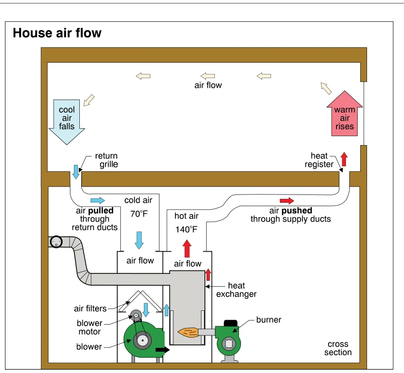
0711House air flow
· p. 112
The illustration shows a cross section of a house and a forced-air heating system, with arrows tracing air circulation through the room, ducts, and furnace. Cool room air falls toward a floor-level return grille and is pulled through return ducts toward the air filters and blower. The furnace includes a blower motor, blower, burner, and heat exchanger, with the circulating air heated before entering the supply duct. Return air is labeled 70°F and supply air 140°F. Heated air is pushed through the supply duct to a floor-level heat register, rises in the room, and flows across the upper portion of the room toward the return side.
 0712
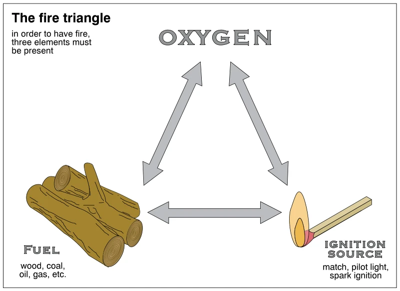
0712The fire triangle
· p. 112
The diagram depicts the three elements necessary for fire: oxygen, fuel, and an ignition source. Three double-headed arrows form a triangle connecting these elements. Logs represent fuel, with wood, coal, oil, and gas listed as examples. A burning match represents an ignition source, with a match, pilot light, and spark ignition listed as examples. No heating appliance assembly or installation defect is shown.
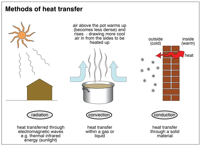 0713
0713Methods of heat transfer
· p. 112
The illustration explains three methods of heat transfer using sunlight reaching a house, air moving above a pot, and heat passing through a brick wall. Radiation is represented by wavy lines traveling from the sun toward the house. Convection is shown by warmed, less-dense air rising above the pot and arrows indicating cooler air entering from the sides. Conduction is shown by a heat arrow passing through the wall from the warm interior toward the cold exterior, where snowflake symbols indicate cold conditions.
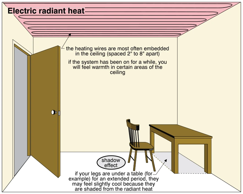 0714
0714Electric radiant heat
· p. 112
The illustration shows a room with electric heating wires arranged in a serpentine pattern across the ceiling. A callout explains that the wires are most often embedded in the ceiling, spaced 2 to 8 inches apart, and that areas of the ceiling feel warm after the system has operated for a while. A table and chair demonstrate the shadow effect of radiant heating, with a shaded area beneath the table. The annotation explains that a person's legs under the table may feel slightly cool because the tabletop blocks radiant heat from the ceiling.
 0715
0715Insulation behind radiators
· p. 112
The cross section shows a radiator beside an outside wall, with foil-coated insulation installed between the radiator and wall. The foil coating faces the radiator to reflect radiant heat back into the room. Wavy arrows depict radiant heat leaving the radiator, while upward arrows indicate convection above and beside it. The annotations explain that room air is heated primarily by convection as cooler air passes over the hot radiator and rises. The radiator stands on the floor above the illustrated floor framing.
Furnaces – Gas And Oil ·Gas Piping and Metersp. 113
 0716
0716Radiator covers
· p. 113
The illustration shows a cross section of a radiator positioned against an outside wall, with a cover over its top and in front of it. Curved arrows illustrate airflow around the radiator and toward the room. The annotations explain that covers restrict airflow past the radiator, reducing its convective heating performance. They also note that covers increase heat loss to the outdoors through the wall. The floor framing and a portion of the foundation are visible below the assembly.
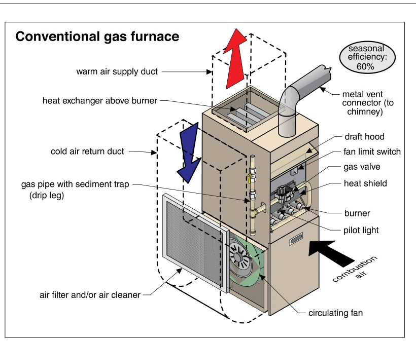 0716.3
Conventional gas furnace
· p. 113
A cutaway illustration shows a conventional gas-fired forced-air furnace with a labeled seasonal efficiency of 60%. Cold return air passes through an air filter or air cleaner into the lower circulating-fan compartment, and heated air exits through the warm-air supply duct above the heat exchanger. The burner and pilot light sit below the heat exchanger, with a gas valve, heat shield, and fan limit switch identified. An external gas pipe includes a sediment trap (drip leg), while a draft hood and metal vent connector provide a path toward the chimney. A separate arrow indicates combustion air entering the furnace; no defects are identified.
 0716.6
Mid-efficiency gas furnace
· p. 113
A cutaway illustration shows a mid-efficiency gas furnace labeled with a seasonal efficiency of 80%. Cold return air enters through the side-mounted filter or air cleaner, and a circulating fan in the lower compartment moves air upward past the heat exchanger into the warm air supply duct. The burner sits below the heat exchanger and is served by a gas valve, gas piping with a sediment trap, and an intermittent pilot or igniter. An induced draft fan connects to a metal vent connector at the top, with an annotation noting that there is no draft hood. A separate arrow indicates combustion air entering the furnace, and a fan limit switch is identified above the burner compartment.
 0716.9
High efficiency gas furnace
· p. 113
A cutaway diagram shows a high-efficiency gas furnace with a lower house-air blower and filter, primary and secondary heat exchangers, and an upper warm-air supply duct. Dashed duct outlines and colored arrows indicate cold return air entering the furnace and heated air leaving at the top. The burner assembly includes a gas valve, intermittent pilot or igniter, and gas piping with a sediment trap. An induced draft fan connects to a PVC or ABS plastic vent pipe, and the illustration explicitly notes that there is no draft hood. A condensate drain serves the condensing furnace, while a separate arrow indicates combustion air entering the cabinet; seasonal efficiency is labeled 90+%.
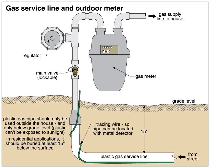 0717
0717Gas service line and outdoor meter
· p. 113
The illustration shows an underground plastic gas service line arriving from the street and turning upward to an outdoor gas meter assembly. Above grade, the inlet piping includes a lockable main valve and a regulator before connecting to the meter; the outlet supplies gas to the house. A tracing wire runs alongside the buried plastic pipe so it can be located with a metal detector. The drawing specifies at least 15 inches of burial for residential applications and states that plastic gas piping should be used only outdoors below grade, protected from sunlight.
 0718
0718Ice on regulator
· p. 113
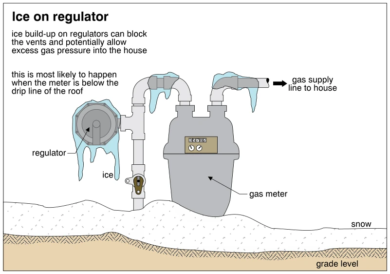
The illustration shows an exterior gas meter, pressure regulator, shutoff valve, and connected gas piping above grade. Ice coats the regulator and portions of the piping, with icicles hanging beneath them. Snow covers the ground around the base of the meter installation. The annotations warn that ice buildup can block regulator vents and potentially allow excessive gas pressure into the house. They identify a meter location below the roof drip line as particularly susceptible to this condition.
 0719
0719Poor meter locations
· p. 114
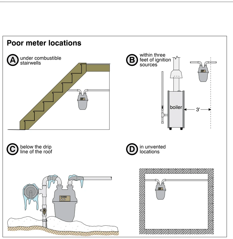
The illustration shows four improper gas meter locations. Panel A places a meter and its piping beneath a combustible stairwell. Panel B shows a meter within three feet of a boiler, identified as an ignition source. Panel C depicts an outdoor meter assembly below the roof drip line, with ice on the regulator and piping and snow at ground level. Panel D places a meter inside an enclosed, unvented space.
 0720
0720Gas piping terminology
· p. 114
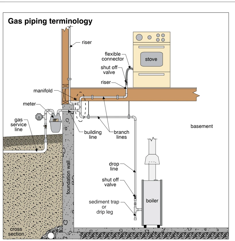
The cross-sectional drawing traces an underground gas service line to an exterior meter and through the foundation wall into the building. A building line connects to a manifold serving branch lines and risers. One branch rises through the floor to a stove, with a shut off valve and flexible connector at the appliance. Another branch runs across the basement and down a drop line to a boiler, with a shut off valve and a capped sediment trap or drip leg below the appliance connection. The illustration identifies gas piping terminology without highlighting a defect.
 0721
0721Flexible gas appliance connectors
· p. 114
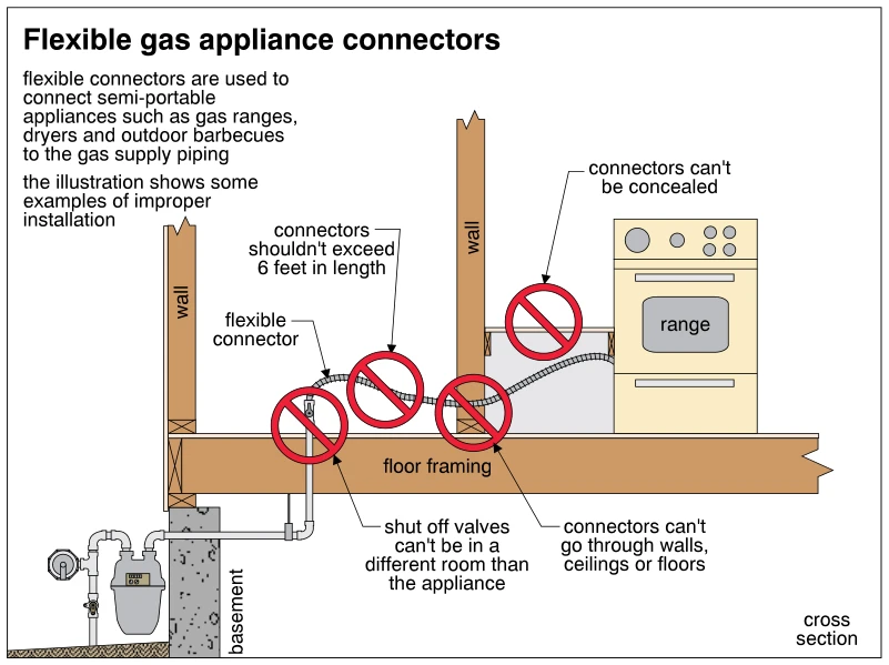
The cross section shows gas supply piping and a meter at basement level feeding a flexible connector serving a gas range above. Red prohibition symbols identify improper connector installation conditions. The annotations warn against connectors longer than 6 feet, concealed connectors, and connectors passing through walls, ceilings or floors. A further warning states that the shutoff valve cannot be in a different room from the appliance.
 0722
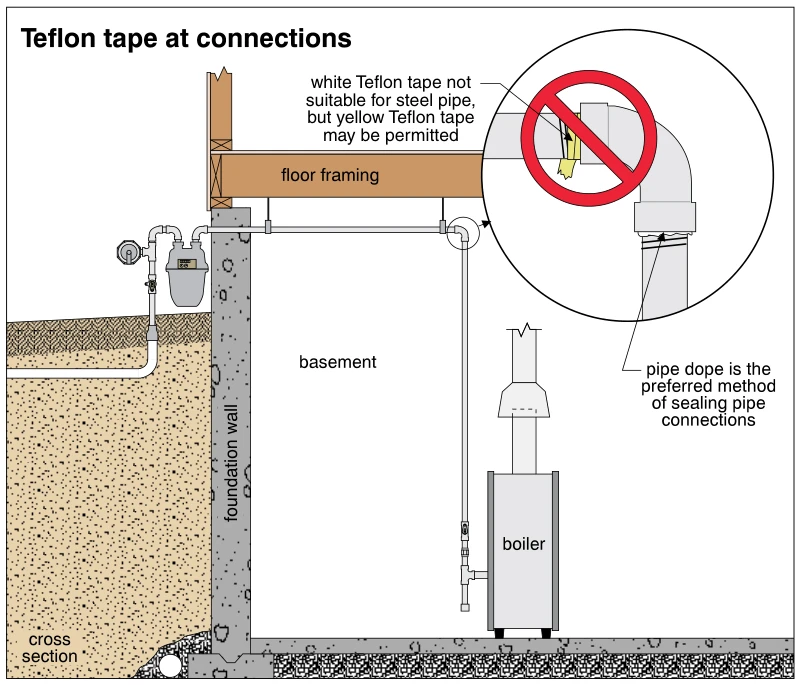
0722Teflon tape at connections
· p. 114
A cross section shows a gas service entering an exterior meter assembly and continuing through the foundation wall to a basement boiler. The interior gas piping runs beneath the floor framing before turning downward to the boiler connection. An enlarged detail of a threaded elbow connection has a prohibition symbol over thread-sealing tape. The annotation states that white Teflon tape is not suitable for steel pipe, although yellow Teflon tape may be permitted, and identifies pipe dope as the preferred method of sealing pipe connections.
 0723
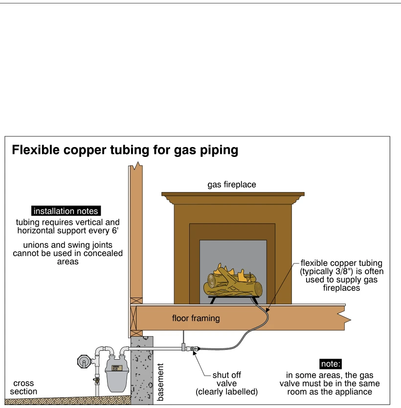
0723Flexible copper tubing for gas piping
· p. 115
The cross-section shows a gas fireplace above floor framing, supplied by flexible copper tubing connected to gas piping in the basement. An exterior gas meter and regulator connect to piping that passes through the foundation wall, with a labelled shutoff valve upstream of the flexible tubing. The tubing curves upward through the floor to the fireplace. Installation notes call for vertical and horizontal support every six feet and prohibit unions and swing joints in concealed areas. A separate note states that some areas require the gas valve to be in the same room as the appliance.
 0724
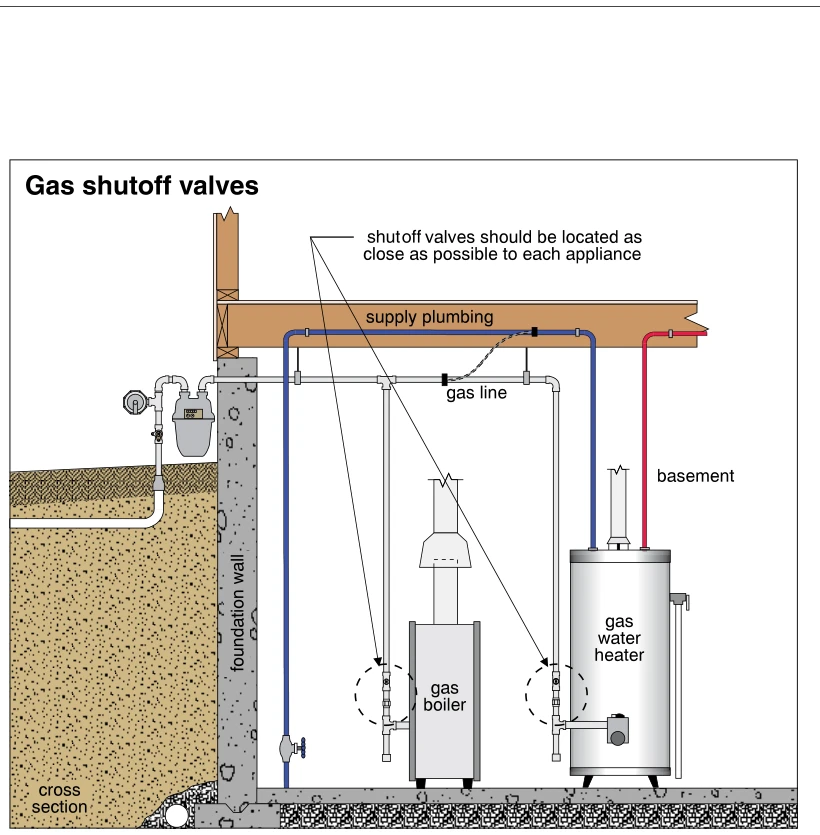
0724Gas shutoff valves
· p. 115
A basement cross section shows an exterior gas meter supplying a gas line through the foundation wall. The gas line runs overhead and branches down to a gas boiler and a gas water heater. Dashed circles and arrows highlight individual shutoff valves on the vertical gas branches immediately beside each appliance. The annotation specifies that shutoff valves should be located as close as possible to each appliance. Water supply piping and appliance vent connections are also shown.
 0725
0725Grounding the gas piping
· p. 115
A basement cross section shows a gas service passing through an exterior meter and foundation wall to supply a gas water heater. Water supply piping runs overhead and connects to the heater, while a ground wire connects the electrical service equipment to the water supply piping near the basement floor. A dashed circle highlights a bonding jumper between the overhead gas line and water supply piping. The annotation states that, in many areas, gas piping must be bonded to the electrical grounding system, typically by bonding it to the supply piping.
 0726
0726Gas piping support
· p. 115
The illustration shows a building cross section with an exterior gas meter and gas piping passing through a foundation wall to a basement boiler and a vertical riser. The riser is supported at the floor level, with an annotation requiring vertical support at every floor, while hangers support the horizontal basement piping from the framing above. Dimension arrows specify steel piping support intervals of 6, 8, or 10 feet according to pipe diameter. Separate annotations give copper and CSST support intervals of 4, 6, 8, or 10 feet according to tubing size. Notes state that CSST spacing varies by manufacturer and that, for Canadian readers, all tubing has a 6-foot horizontal support interval.
Furnaces – Gas And Oil ·Combustion Airp. 116
 0727
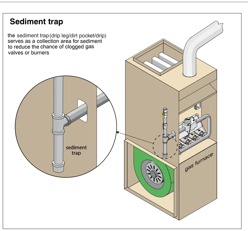
0727Sediment trap
· p. 116
The illustration shows a gas furnace with its burner and blower compartments exposed and a sediment trap installed in the external gas supply piping. The vertical supply pipe has a shutoff valve above a tee whose side outlet feeds the furnace. A capped pipe nipple extends below the tee to collect sediment before it reaches the gas valve or burners. A circular enlargement details the tee, furnace supply branch, and capped sediment pocket.
 0728
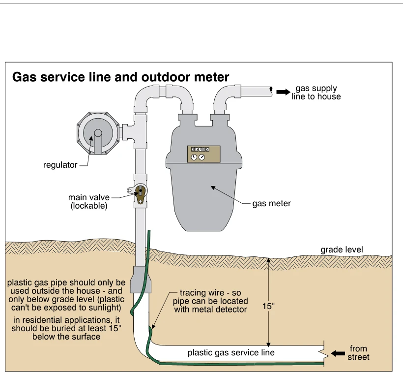
0728Gas service line and outdoor meter
· p. 116
The illustration shows an underground plastic gas service line from the street rising to an outdoor gas meter assembly. A tracing wire follows the buried pipe, and a vertical dimension indicates 15 inches of burial below grade. The aboveground assembly includes a lockable main valve, regulator, gas meter, and outlet piping supplying the house. Annotations specify that plastic gas piping is for outdoor, below-grade use only, must not be exposed to sunlight, and should be buried at least 15 inches in residential applications.
 0729
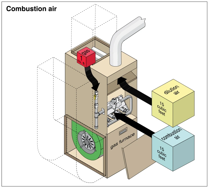
0729Combustion air
· p. 116
A cutaway gas furnace shows the gas piping, burner assembly, lower circulating-air blower, and upper vent connector. A red cube represents 1 cubic foot of gas supplied to the appliance. Two larger cubes each represent 15 cubic feet of air: combustion air directed toward the burners and dilution air directed toward the upper vent opening. Black arrows distinguish these three inputs, illustrating the air requirements associated with gas furnace operation.
 0730
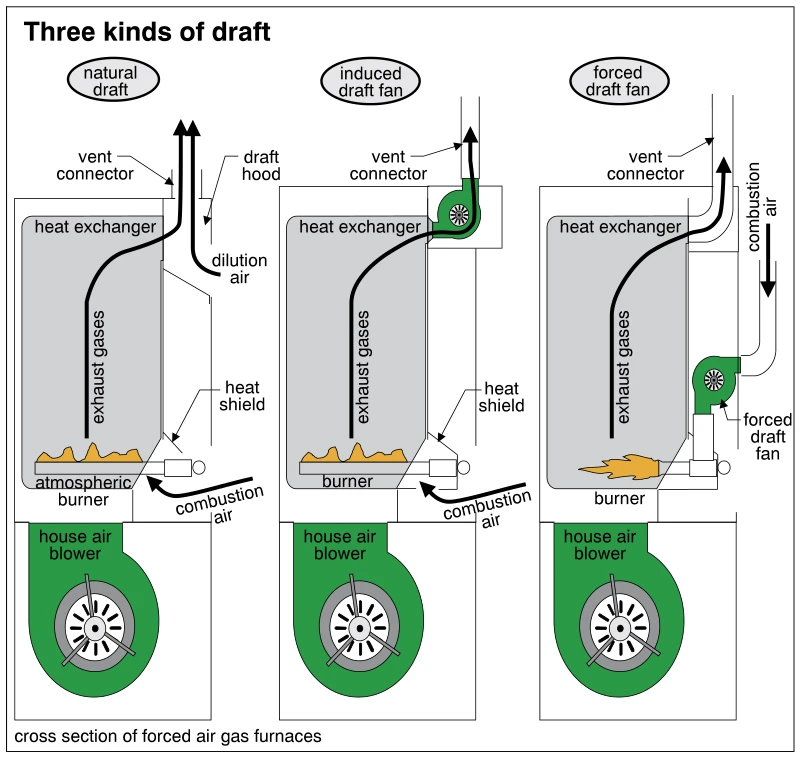
0730Three kinds of draft
· p. 116
Three cross sections compare natural, induced, and forced draft arrangements in forced-air gas furnaces. The natural-draft furnace has an atmospheric burner, a heat exchanger, and a draft hood admitting dilution air into the vent connector. The induced-draft arrangement places a fan at the heat exchanger outlet to draw exhaust gases toward the vent connector. The forced-draft arrangement places a fan on the combustion-air inlet to supply air to the burner. Each furnace has a separate house-air blower below the heat exchanger, and arrows indicate combustion-air and exhaust-gas flow.
 0731
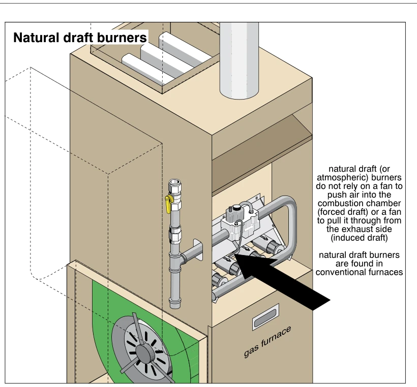
0731Natural draft burners
· p. 117
The illustration shows a conventional gas furnace with its burner compartment exposed and its lower blower compartment partly open. A gas supply pipe with a shutoff valve connects to the gas control and burner assembly, highlighted by a large arrow. A vertical vent pipe exits the top of the furnace, beside an opening showing internal heat-exchanger passages. The annotations explain that natural draft, or atmospheric, burners use neither a forced-draft fan to push combustion air in nor an induced-draft fan to pull it through from the exhaust side. The blower shown below the burners is separate from the combustion draft arrangement.
 0732
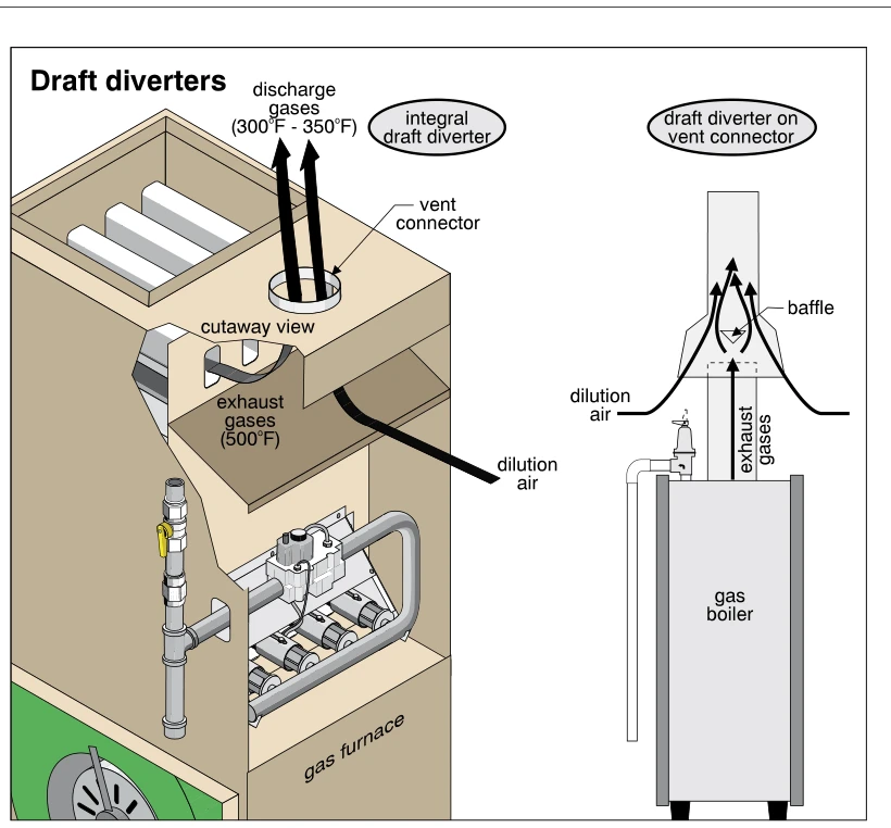
0732Draft diverters
· p. 117
The illustration shows two draft-diverter arrangements for gas-fired heating appliances: an integral diverter in a furnace and a diverter on a boiler vent connector. The furnace cutaway exposes the burners, gas piping, and internal exhaust path, with arrows showing dilution air entering the diverter and discharge gases rising through the vent connector. Furnace exhaust gases are labeled 500°F, while discharge gases after dilution are labeled 300°F–350°F. The boiler schematic shows exhaust rising toward a baffle while dilution air enters from the open sides of the draft hood and joins the upward flow. No defects or improper installations are identified.
 0733
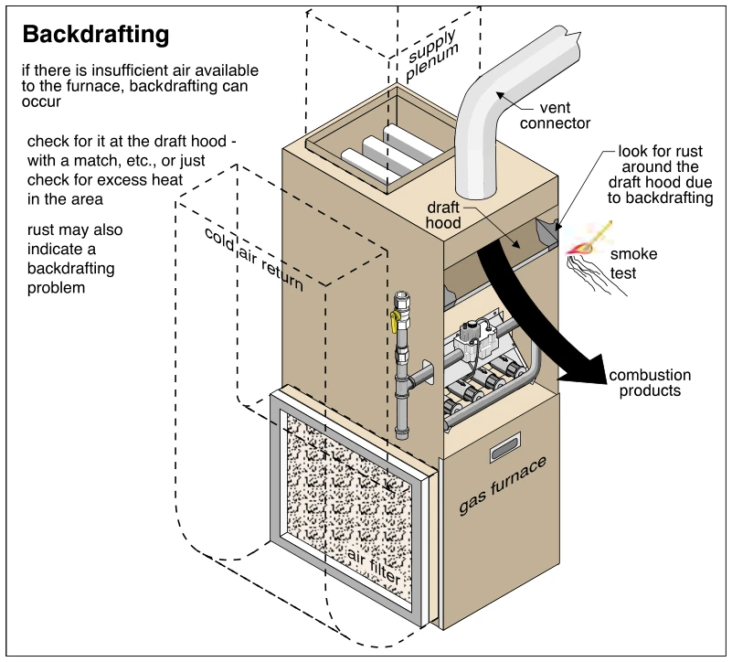
0733Backdrafting
· p. 117
The illustration shows a gas furnace with a draft hood, an upward-curving vent connector, and dashed outlines of the supply plenum and cold air return. The open front exposes the burner assembly and gas controls, while an air filter is shown at the return side. A large arrow depicts combustion products spilling out through the draft hood rather than exhausting through the vent connector. Annotations identify insufficient air as a cause of backdrafting and indicate rust and excess heat around the draft hood as possible warning signs. A smoke test is illustrated beside the draft hood to check draft direction.
 0734
0734Furnace room air openings
· p. 117
The illustration shows a gas furnace and a cylindrical water heater in a furnace room with high and low louvered air openings through an inside wall. The low opening is labeled with a net vent area of 1 square inch per 1,000 BTUs and placement within 12 inches of the floor in the US or 6–18 inches in Canada. The high opening has the same area designation and corresponding distances from the ceiling, and is identified as an additional opening for appliances with atmospheric burners and draft hoods. A note states that the openings provide both combustion and dilution air. Furnace ductwork, a furnace vent connector, and the water heater's draft hood and piping are also visible.
Furnaces – Gas And Oil ·Gas Burnersp. 118
 0735
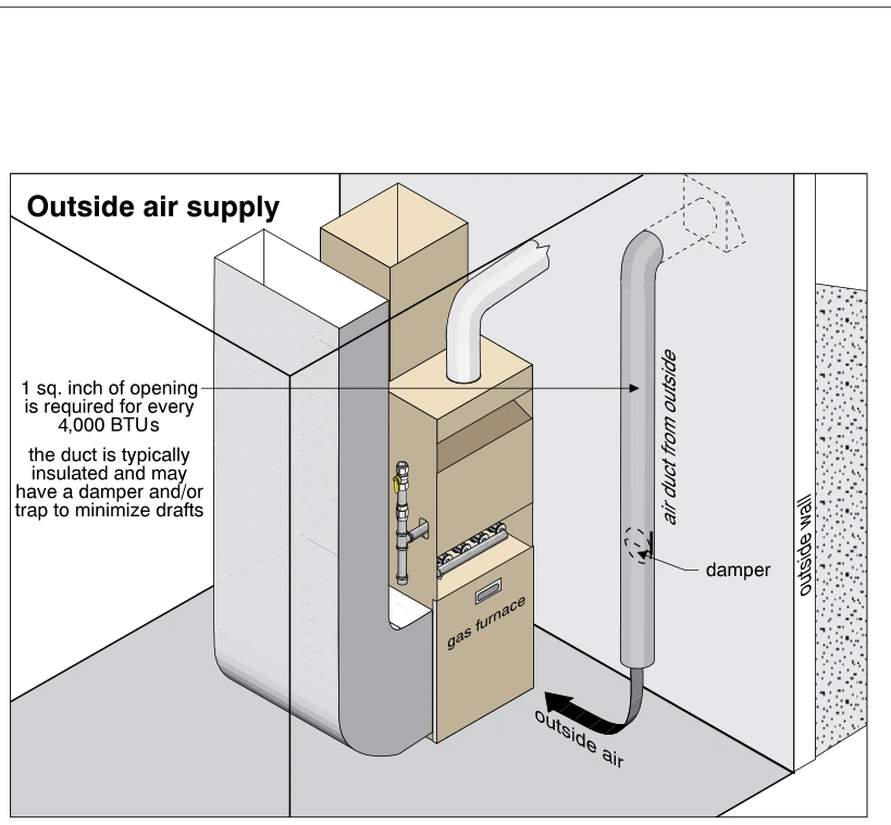
0735Outside air supply
· p. 118
The illustration shows an outdoor combustion-air supply duct beside a gas furnace. The duct passes through the outside wall at a high level and descends to discharge near the floor, with an arrow indicating incoming outside air. A damper is identified in the vertical duct, and an annotation notes that the duct is typically insulated and may have a damper and/or trap to minimize drafts. Another annotation specifies 1 square inch of opening for every 4,000 BTUs. The furnace is shown with adjacent distribution ductwork, exposed gas piping and burners, and a vent connector rising from its top.
 0736
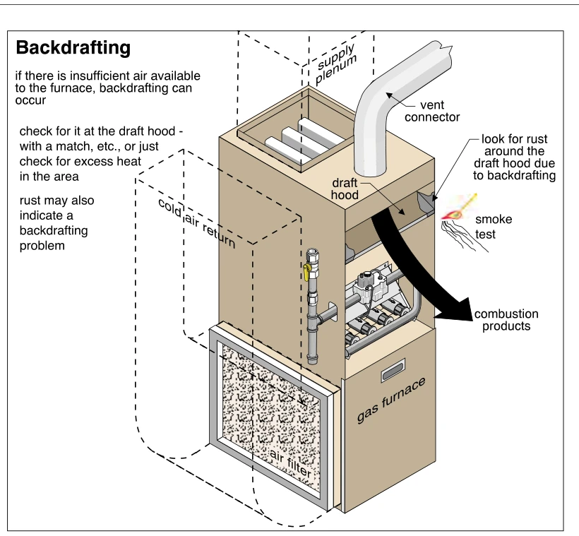
0736Backdrafting
· p. 118
The illustration depicts a gas furnace with a draft hood, vent connector, gas piping and burners, supply plenum, and cold air return with an air filter. A large arrow shows combustion products spilling outward from the draft hood rather than exiting through the vent connector. A smoke test is illustrated at the draft hood, and a callout identifies rust around the hood as a possible indication of backdrafting. The annotations explain that insufficient air available to the furnace can cause backdrafting and identify excess heat near the draft hood as another warning sign.
 0737
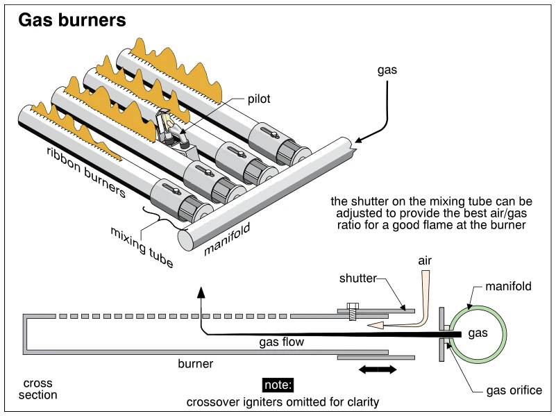
0737Gas burners
· p. 118
The illustration shows four parallel ribbon burners supplied by a common gas manifold, with flames along the burner ports and a pilot between the burners. Each burner connects to the manifold through a mixing tube with an adjustable shutter. A cross-sectional detail shows gas passing from the manifold through a gas orifice into the burner while air enters through the shutter opening. Arrows indicate gas flow toward the burner ports and the direction of shutter adjustment. An annotation explains that the shutter adjusts the air/gas ratio for a good flame, and a note states that crossover igniters are omitted for clarity.
 0738
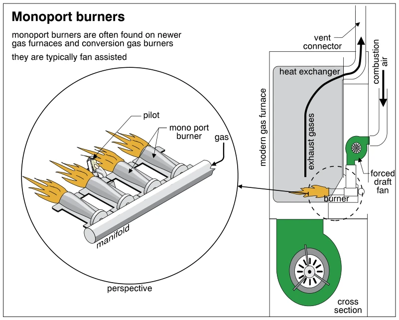
0738Monoport burners
· p. 118
The illustration combines a perspective detail of a monoport gas burner assembly with a cross section of a modern gas furnace. Four burners connect to a common gas manifold, with flames projecting from their outlets and a pilot identified beside the assembly. The furnace cross section shows the burner firing into the heat exchanger, with exhaust gases flowing upward to the vent connector. A forced draft fan supplies combustion air to the burner area, and a separate large blower is shown below the heat exchanger. The annotations identify monoport burners as typically fan assisted and commonly found on newer gas furnaces and conversion gas burners.
 0739
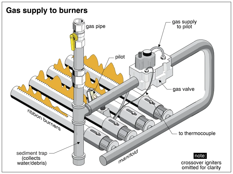
0739Gas supply to burners
· p. 118
The illustration shows a gas supply assembly feeding a bank of ribbon burners, with flames drawn along the burner ports. A vertical gas pipe with a manual shutoff branches toward the gas valve, while its capped lower extension forms a sediment trap to collect water and debris. Piping from the gas valve loops around to a manifold supplying the individual burners. Small connections at the gas valve are identified as the gas supply to the pilot and the connection to the thermocouple. A note states that crossover igniters are omitted for clarity.
 0740
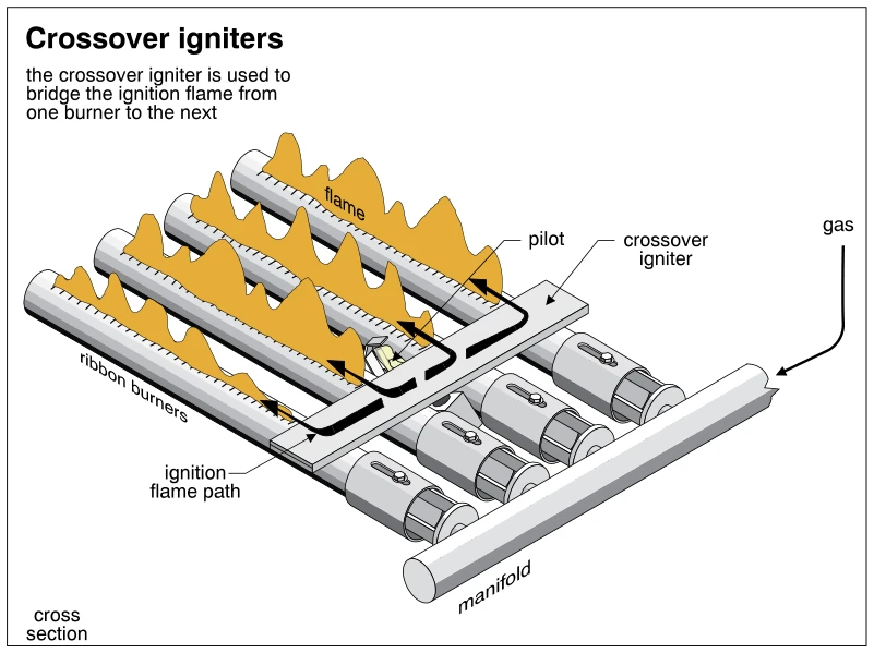
0740Crossover igniters
· p. 118
The illustration shows four parallel ribbon gas burners supplied by a common gas manifold. A crossover igniter extends across the burners near their inlet ends, with a pilot identified beside the burner assembly. Black arrows trace the ignition flame path from one burner to the next through the crossover arrangement. Yellow flames rise along the burner ribbons, illustrating the intended propagation of ignition across the assembly.
 0741
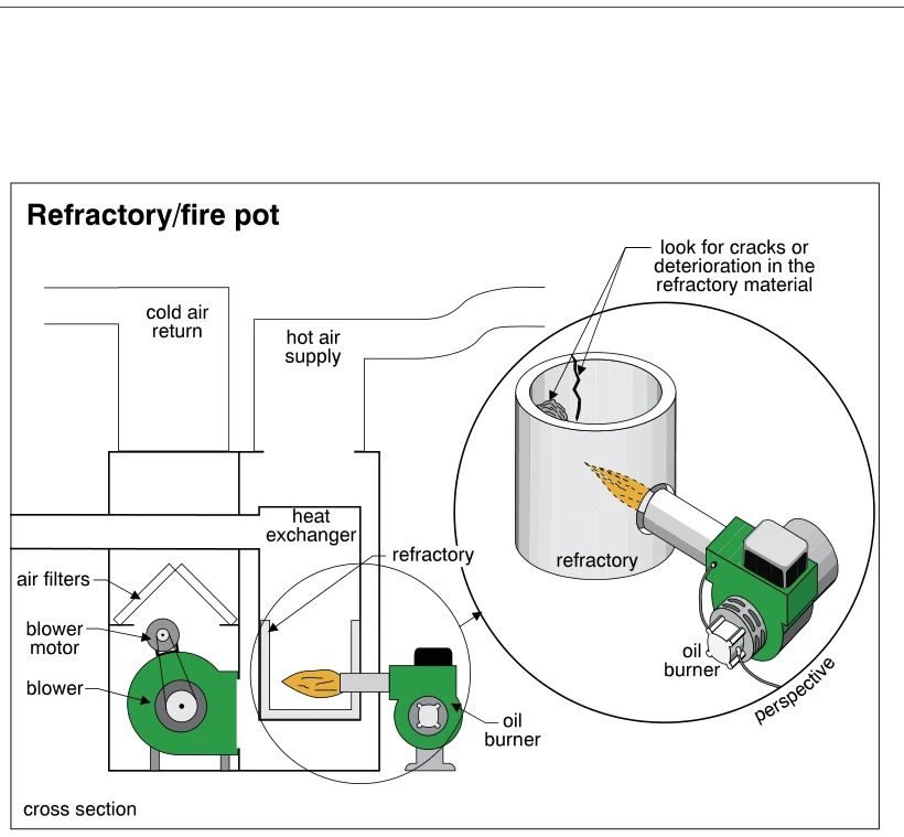
0741Refractory/fire pot
· p. 119
The illustration shows a furnace cross section and an enlarged perspective of its refractory fire pot and oil burner. The cross section locates the air filters, belt-driven blower, heat exchanger, cold air return, and hot air supply. The oil burner projects a flame into the refractory-lined combustion chamber at the base of the heat exchanger. The perspective view shows a cylindrical fire pot with a crack and a deteriorated patch on its inner surface. An annotation directs the inspector to look for cracks or deterioration in the refractory material.
 0742
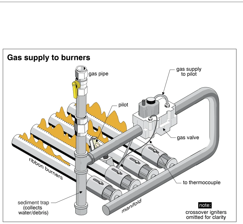
0742Gas supply to burners
· p. 119
The illustration shows a gas supply assembly feeding four ribbon burners with flames along their lengths. The vertical gas pipe includes a lever-operated shutoff and a capped sediment trap below the branch supplying the gas valve. Piping from the gas valve loops around to a manifold connected to the burner inlets. A small tube supplies the pilot, and a separate connection is labeled as leading to the thermocouple. A note states that crossover igniters are omitted for clarity.
 0743
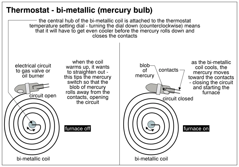
0743Thermostat - bi-metallic (mercury bulb)
· p. 119
The illustration shows two operating states of a bi-metallic coil thermostat with a mercury bulb switch. On the left, warming causes the coil to straighten and tilt the bulb so mercury moves away from the contacts, opening the electrical circuit and turning the furnace off. On the right, cooling tilts the bulb so mercury moves toward the contacts, closing the circuit and starting the furnace. The coil's central hub connects to the temperature-setting dial; turning the dial down counterclockwise requires a cooler temperature before the contacts close. The controlled circuit is identified as serving a gas valve or oil burner.
 0744
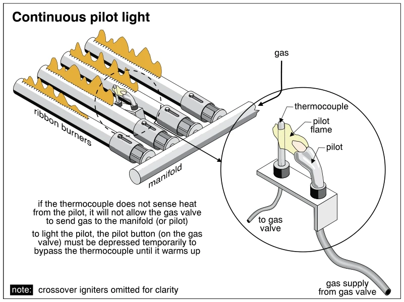
0744Continuous pilot light
· p. 119
The illustration shows parallel ribbon burners supplied by a common gas manifold, with flames along the burners. An enlarged detail shows the continuous pilot beside a thermocouple, with the pilot flame heating the thermocouple tip. Separate connections lead from the pilot and thermocouple toward the gas valve. Annotations explain that loss of pilot heat prevents the gas valve from supplying the manifold or pilot, and that the pilot button temporarily bypasses this safety function during lighting until the thermocouple warms up. Crossover igniters are explicitly omitted for clarity.
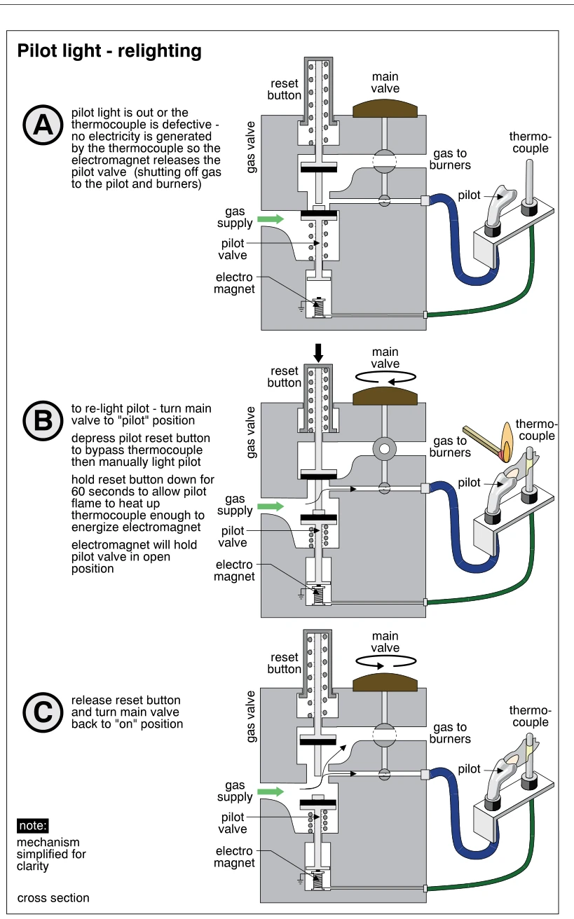 0745
0745Pilot light - relighting
· p. 120
Three simplified cross sections illustrate a standing-pilot gas valve during pilot failure, relighting, and restored operation. Panel A shows the pilot extinguished or the thermocouple defective, causing the electromagnet to release the pilot valve and shut off gas to both the pilot and burners. Panel B shows the main valve in the pilot position and the reset button depressed while a match lights the pilot; the annotation specifies holding the button for 60 seconds to heat the thermocouple and energize the electromagnet. Panel C shows the reset button released, the main valve returned to the on position, and flow arrows indicating gas delivery to the pilot and burners. Each panel shows the pilot tubing and the thermocouple connection to the gas valve.
 0746
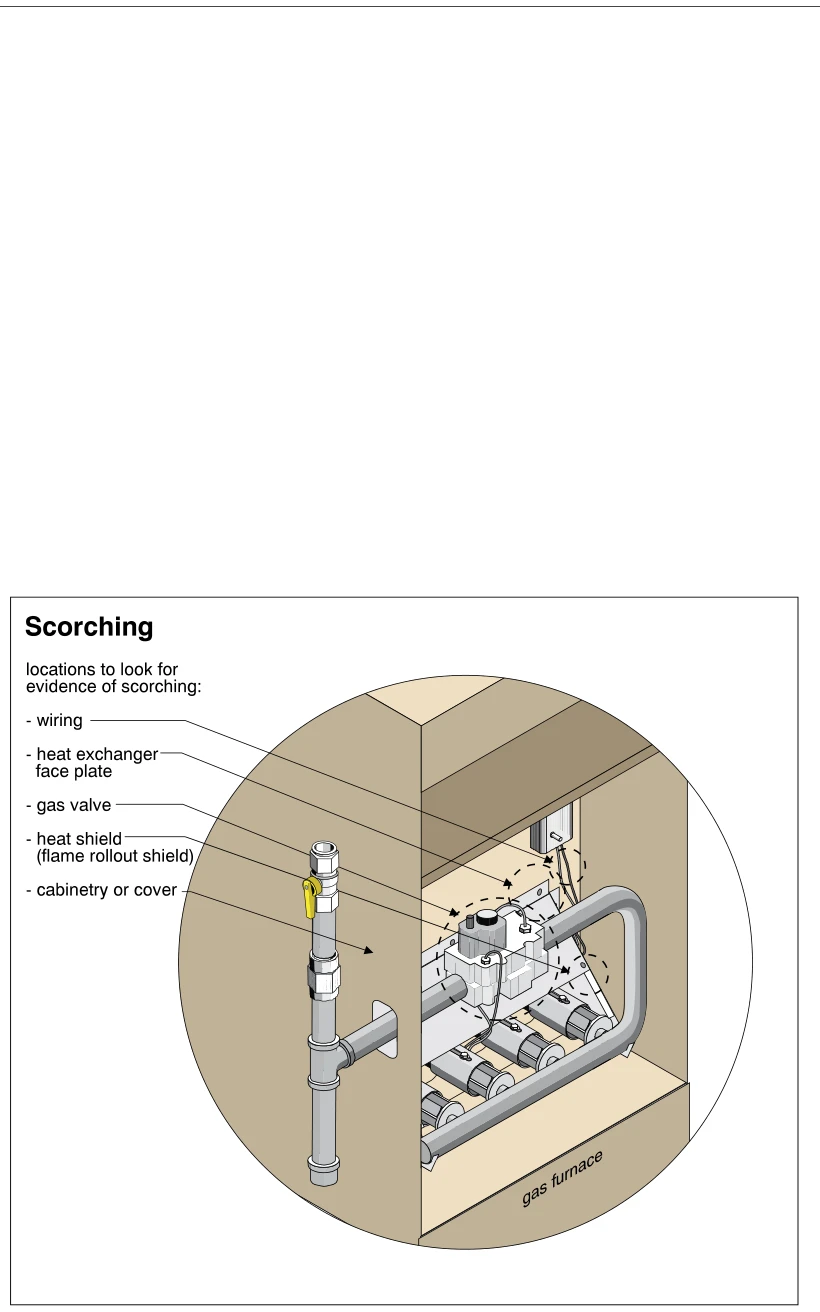
0746Scorching
· p. 120
The illustration shows a gas furnace with its burner compartment exposed, revealing a row of burners, gas piping, a gas valve, and wiring. Arrows identify locations to inspect for scorching: wiring, the heat exchanger face plate, the gas valve, the flame rollout shield, and the cabinetry or cover. Dashed outlines highlight areas around components in the burner compartment. The figure is an inspection-location guide for evidence of abnormal heating rather than a comparison of installation methods.
Furnaces – Gas And Oil ·Heat Exchangersp. 121
 0747
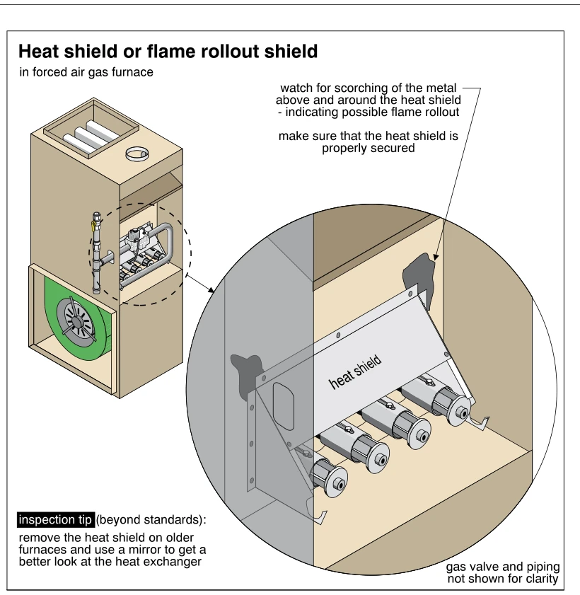
0747Heat shield or flame rollout shield
· p. 121
The illustration shows a forced-air gas furnace with an enlarged view of the burner compartment and its heat shield, also called a flame rollout shield. The shield is mounted across the front of a row of gas burners. Dark scorched areas on the metal above and around the shield are identified as evidence of possible flame rollout. An annotation emphasizes that the shield should be properly secured. An inspection tip describes removing the shield on older furnaces and using a mirror to improve the view of the heat exchanger; the gas valve and piping are omitted from the enlarged view for clarity.
 0748
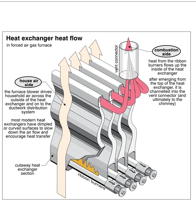
0748Heat exchanger heat flow
· p. 121
The illustration shows a cutaway of a forced-air gas furnace heat exchanger with ribbon burners beneath multiple curved exchanger sections. Pink arrows trace the combustion-side flow upward through the interiors of the sections and into the vent connector. Pale arrows show household air moving upward across the outside surfaces of the exchanger, separate from the combustion stream. An annotation explains that the furnace blower moves this air onward to the ductwork distribution system. The curved exchanger surfaces slow airflow and encourage heat transfer; no defect is depicted.
 0749
0749Draft diverters
· p. 121
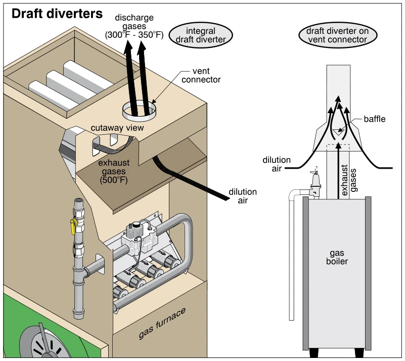
The illustration shows a cutaway gas furnace with an integral draft diverter and a gas boiler with a draft diverter on its vent connector. The furnace cutaway exposes the heat exchanger passages, burner assembly, gas piping, and part of the blower. Arrows show dilution air entering the furnace draft diverter and mixing with exhaust gases labeled 500°F, with discharge gases labeled 300°F - 350°F leaving through the vent connector. The boiler diagram shows exhaust gases rising toward a baffle while dilution air enters through the open sides of the draft diverter. Both arrangements illustrate draft-diverter construction and gas flow without identifying a defect.
 0750
0750House air flow
· p. 121
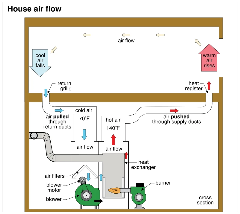
A cross section of a house illustrates air circulation through a forced-air furnace and its supply and return ducts. Cool room air falls toward a return grille and is pulled through the return duct, labeled 70°F, to the furnace filters and blower. The motor-driven blower moves air around the burner-heated heat exchanger, keeping circulating house air separate from the combustion path. Heated air, labeled 140°F, is pushed through the supply duct to a heat register. Arrows show warm air rising, moving across the room, and cooling as it returns toward the return grille.
 0751
0751Exhaust breech through cold air return
· p. 122
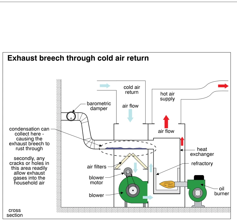
The cross section shows an oil-fired forced-air furnace with a blower, blower motor, air filters, heat exchanger, refractory lining, and oil burner. Blue arrows trace return air downward through the filters and blower, while red arrows show heated air rising into the hot-air supply duct. The exhaust breech runs horizontally through the cold-air return before turning upward toward a wall connection equipped with a barometric damper. A dashed oval highlights condensation collecting in this horizontal section, where corrosion can rust through the breech. The annotations warn that cracks or holes here readily admit exhaust gases into household air.
 0752
0752Heat pump coil upstream of heat exchanger
· p. 122
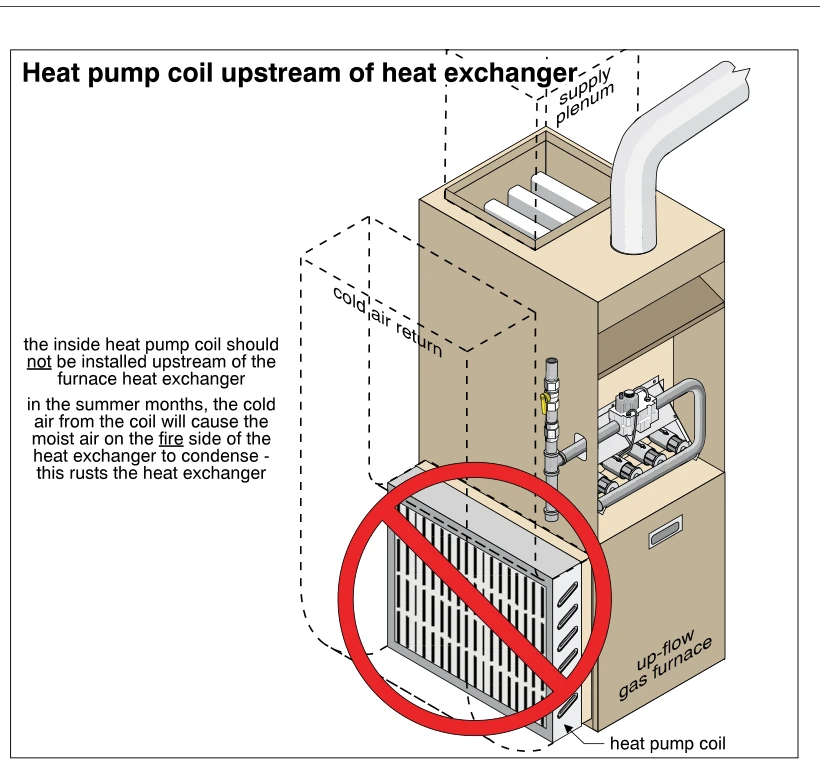
The illustration shows an up-flow gas furnace with an indoor heat pump coil installed in the cold-air return, upstream of the furnace heat exchanger. Dashed outlines indicate the return duct and overhead supply plenum, and the furnace cutaway exposes the gas burner assembly. A red prohibition symbol marks the coil placement as incorrect. The annotation explains that cold air from the coil during summer operation causes moisture to condense on the fire side of the heat exchanger, promoting rust.
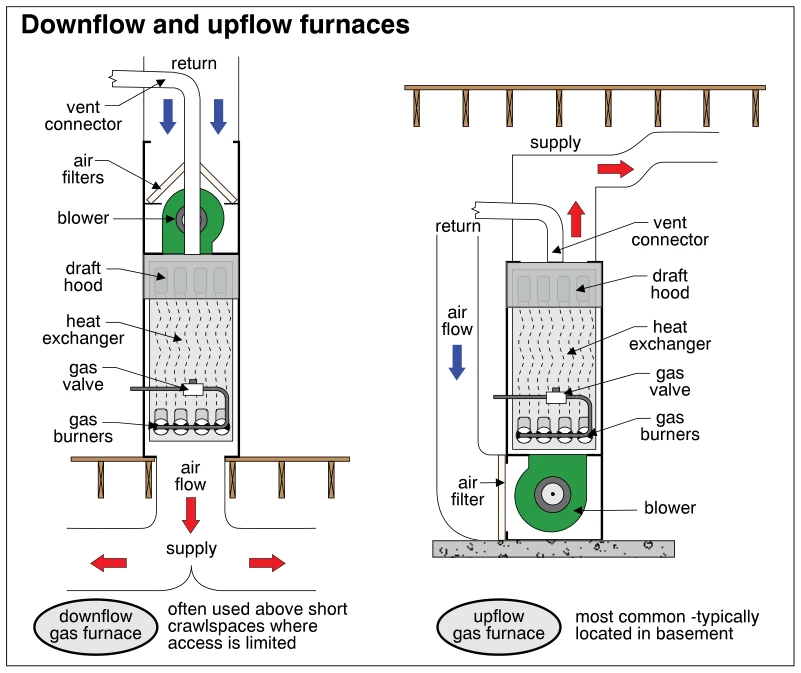 0753
0753Downflow and upflow furnaces
· p. 122
The illustration compares downflow and upflow gas furnaces, showing their internal components and return and supply airflow paths. In the downflow furnace, return air enters at the top through filters, and a blower above the heat exchanger moves air downward to supply ducts beneath the floor. In the upflow furnace, return air travels down a side duct through a filter to a blower below the heat exchanger, then moves upward to an overhead supply duct. Both furnaces show gas burners, a gas valve, a heat exchanger, a draft hood, and a vent connector. Notes associate the downflow arrangement with short crawlspaces with limited access and the upflow arrangement with basement installations.
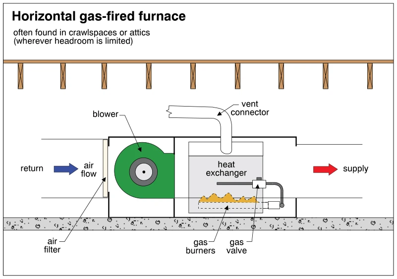 0754
0754Horizontal gas-fired furnace
· p. 122
The illustration shows a horizontal gas-fired furnace installed beneath wood framing in a space with limited headroom. Return air enters from the left through an air filter and is moved by the blower toward the heat exchanger and the supply duct on the right. Gas burners are shown beneath the heat exchanger, with a gas valve connected to the burner piping. A vent connector rises from the heat exchanger area and turns horizontally to the left. The drawing identifies the principal components and airflow direction without depicting a specific defect.
Furnaces – Gas And Oil ·Furnace Cabinetsp. 123
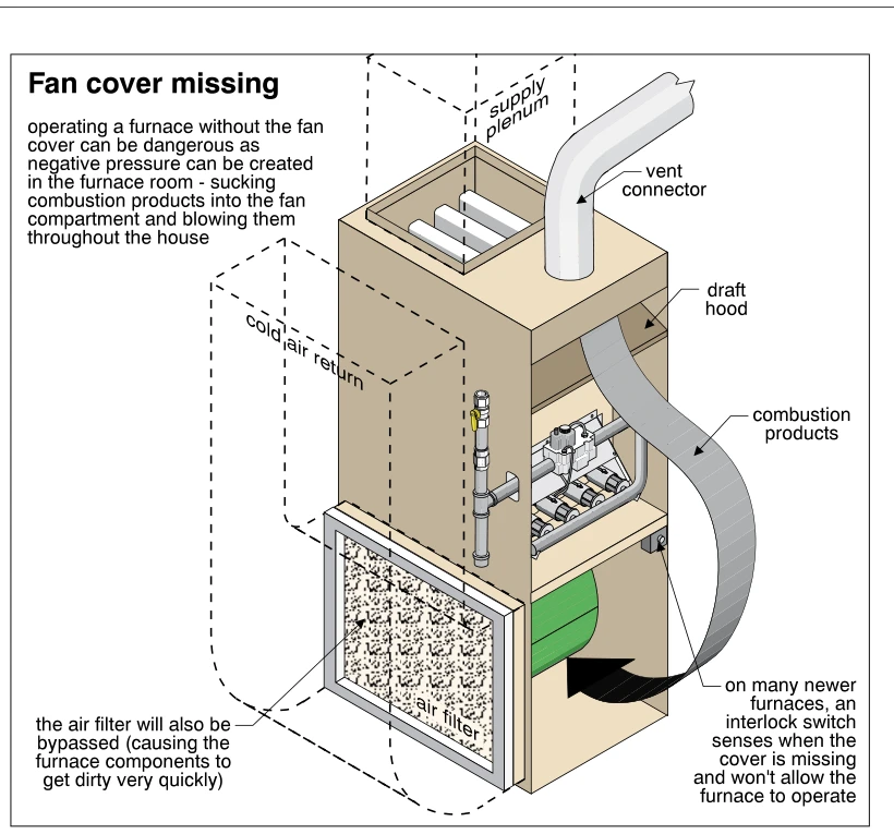 0755
0755Fan cover missing
· p. 123
The illustration shows a forced-air furnace with its lower fan compartment cover missing, exposing the blower. Dashed outlines identify the cold-air return and supply plenum, and an air filter is shown beside the blower compartment. A large curved arrow depicts combustion products being drawn from the draft hood into the open fan compartment for distribution through the house. The annotations explain that operating without the cover can create negative pressure in the furnace room and bypass the filter, rapidly dirtying furnace components. An interlock switch is identified as a feature on many newer furnaces that prevents operation when the cover is absent.
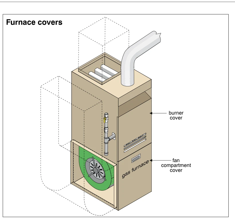 0756
0756Furnace covers
· p. 123
The illustration shows an upright gas furnace with separate front covers for the burner and fan compartments. Arrows identify the upper burner cover and lower fan compartment cover. A cutaway at the lower left reveals the blower housing and motor inside the cabinet. Gas piping runs along the side, a curved vent pipe exits the top, and dashed outlines indicate adjoining ductwork.
 0757
0757Draft diverters
· p. 123
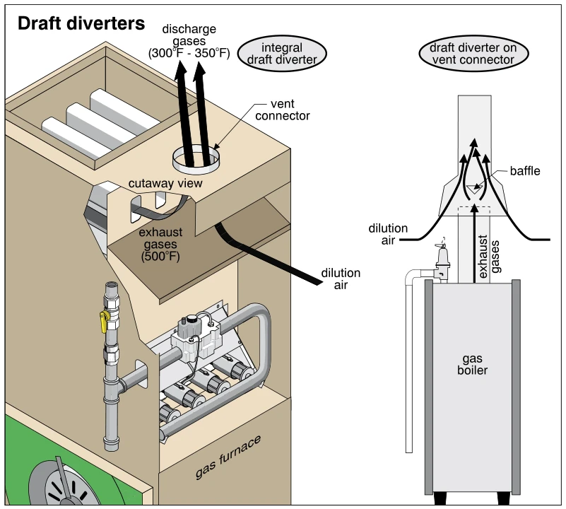
The illustration shows two draft-diverter arrangements for gas-fired heating equipment: an integral diverter in a furnace cabinet and a diverter on a boiler vent connector. The furnace cutaway exposes the burners, gas piping and controls, and the exhaust passage leading to the vent connector. Arrows show dilution air entering the integral diverter and mixing with exhaust gases labeled 500°F, producing discharge gases labeled 300°F–350°F. The boiler diagram shows exhaust rising through a draft diverter with a central baffle while dilution air enters from the open sides and joins the upward flow.
 0758
0758Furnace clearances
· p. 123
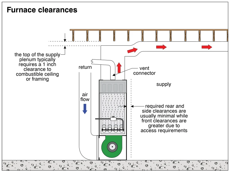
The illustration shows a cutaway of an upflow furnace with a blower at the bottom, heating components above, a return duct on the left, and a supply plenum extending upward into a horizontal duct. Blue and red arrows indicate downward return airflow and upward and horizontal supply airflow, respectively. A vent connector rises from the furnace and turns to the left. Dimension arrows identify the clearance between the supply plenum and the combustible ceiling framing, with an annotation stating that 1 inch is typically required. Another annotation explains that rear and side furnace clearances are usually minimal, while greater front clearance is required for access.
Furnaces – Gas And Oil ·Thermostatsp. 124
 0759
0759Fan switch
· p. 124
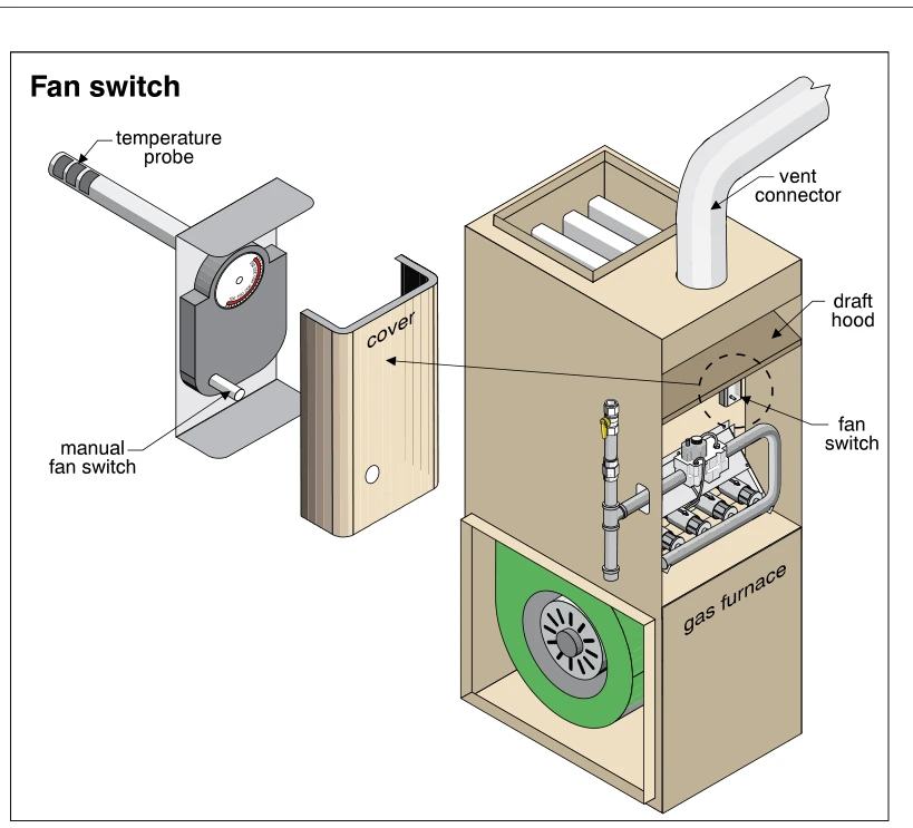
The illustration shows a gas furnace with its front panels removed to expose the burner assembly and lower circulating blower. A fan switch is identified near the upper portion of the burner compartment, below the draft hood. An enlarged view shows the switch with its cover removed, revealing a dial, a manual fan switch, and an elongated temperature probe. The furnace also has a vent connector extending upward from the top and gas piping alongside the burner compartment. No defect or improper installation is indicated.
 0760
0760Fan/limit switch
· p. 124
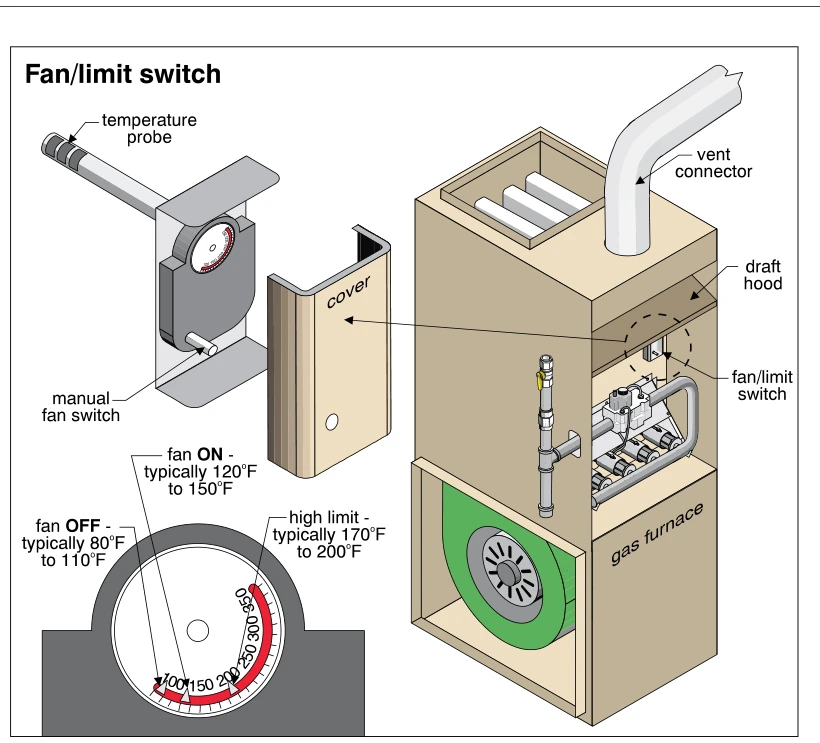
The illustration shows a gas furnace with its blower and burner compartments exposed and the fan/limit switch location identified near the upper burner compartment. An enlarged view of the switch shows its temperature probe, removable cover, adjustment dial, and manual fan switch. A dial detail identifies typical fan-on settings of 120°F to 150°F, fan-off settings of 80°F to 110°F, and high-limit settings of 170°F to 200°F. The furnace also has a draft hood and vent connector above the burners. No defect or improper installation is identified.
 0761
0761Fan/limit switch set wrong or defective
· p. 124
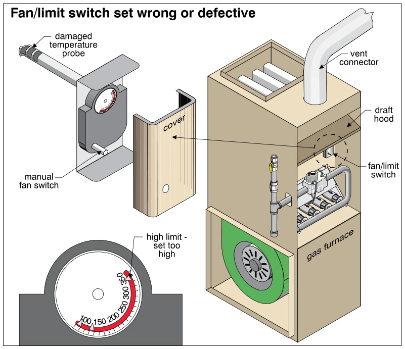
The illustration shows a gas furnace with its blower and burner compartments exposed and the fan/limit switch location identified. An enlarged view of the switch shows its removed cover, manual fan switch, dial, and a damaged temperature probe. A separate dial detail identifies a high-limit setting that is too high. The furnace also has a draft hood and vent connector above the burner compartment. The drawing highlights both physical damage to the temperature-sensing component and improper adjustment of the high-temperature limit.
 0762
0762Thermostat - bi-metallic (mercury bulb)
· p. 124
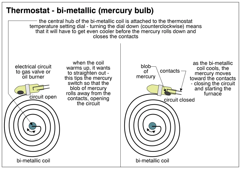
Two diagrams show the operation of a bi-metallic coil thermostat with a mercury bulb switch. On the left, warming causes the coil to straighten and tip the bulb so mercury moves away from the contacts, opening the electrical circuit to the gas valve or oil burner. On the right, cooling tips the bulb in the opposite direction, moving mercury toward the contacts to close the circuit and start the furnace. The central hub connects to the temperature-setting dial; turning the dial down counterclockwise requires a lower temperature before the contacts close.
 0763
0763Thermostat - bi-metallic (snap-action)
· p. 124
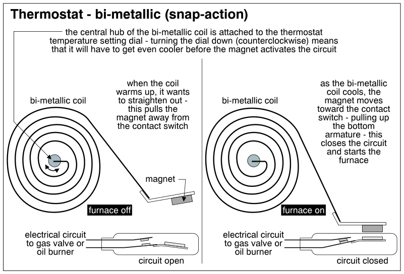
The illustration compares the furnace-off and furnace-on states of a bi-metallic snap-action thermostat. A spiral bi-metallic coil has a central hub attached to the temperature-setting dial and an outer arm carrying a magnet near an electrical contact switch. As the coil warms, it tends to straighten, moving the magnet away from the switch and leaving the furnace control circuit open. As the coil cools, the magnet approaches the switch and pulls up the bottom armature, closing the circuit to the gas valve or oil burner. Turning the setting dial down counterclockwise lowers the temperature at which the magnet activates the circuit.
 0764
0764Variable thermostat anticipator
· p. 124
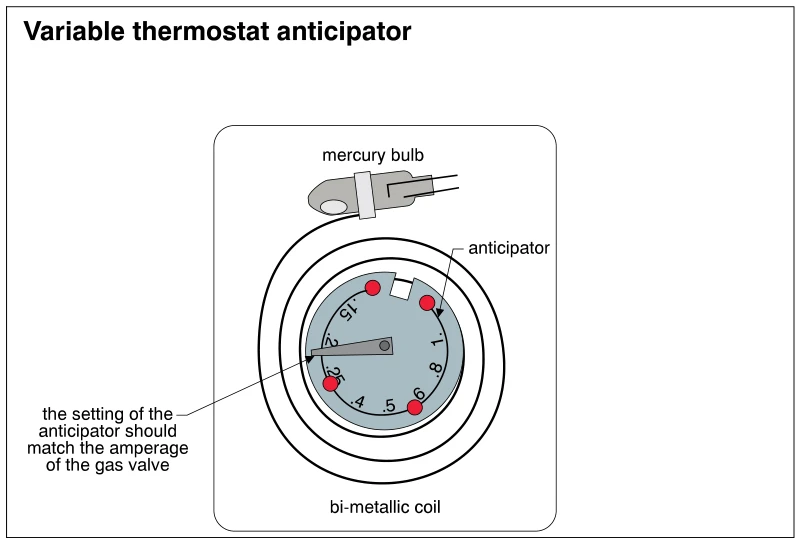
The illustration shows a mechanical thermostat with a spiral bi-metallic coil and a mercury bulb mounted above it. A variable anticipator with a numbered scale and pivoting adjustment pointer occupies the center of the coil. A callout identifies the anticipator and points to its perimeter. An annotation states that the anticipator setting should match the amperage of the gas valve.
Furnaces – Gas And Oil ·Venting Gas Furnacesp. 125
 0765
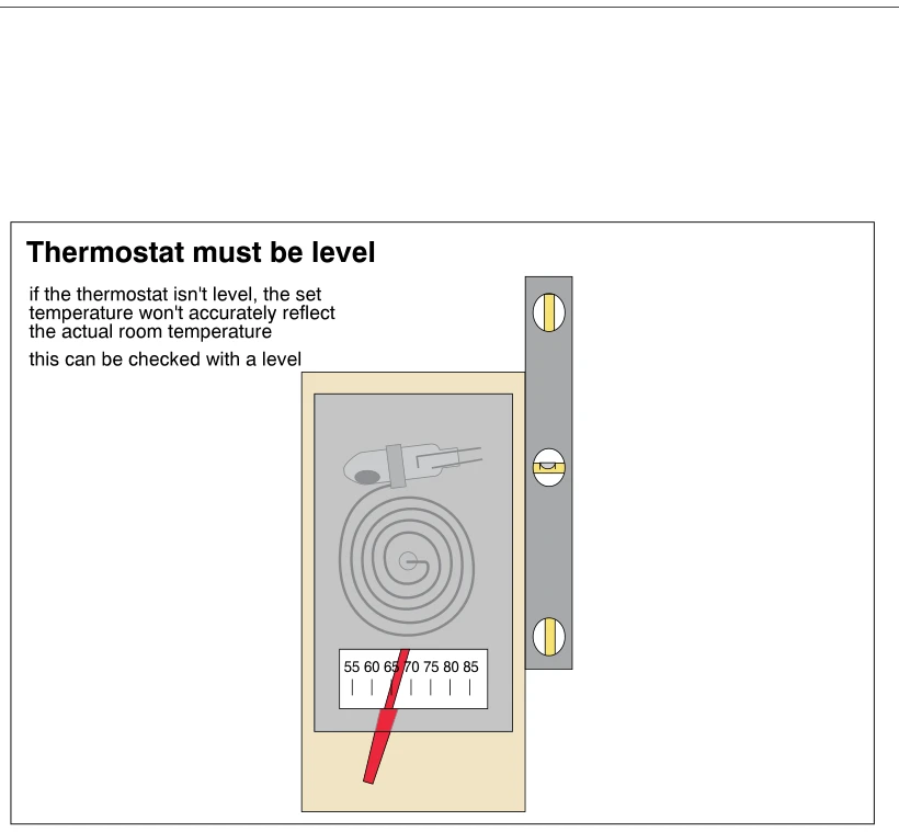
0765Thermostat must be level
· p. 125
The illustration shows a mechanical thermostat with its internal spiral bimetal coil and mercury tilt switch visible. A numbered temperature scale and red adjustment lever are shown below the coil. A spirit level is held vertically against the side of the thermostat housing to check its alignment. The annotations explain that an out-of-level thermostat will not accurately match the set temperature to the actual room temperature.
 0766
0766Draft diverters
· p. 125
The illustration shows a cutaway gas furnace with an integral draft diverter and a gas boiler with a draft diverter on its vent connector. In the furnace, arrows show dilution air entering the diverter and mixing with exhaust gases before discharge through the vent connector. The exhaust gases are labeled 500°F, while the discharge gases are labeled 300°F - 350°F. The boiler diagram shows exhaust gases rising toward a baffle, with dilution air entering from the open sides of the draft diverter and joining the upward flow. No venting defect is depicted.
 0767
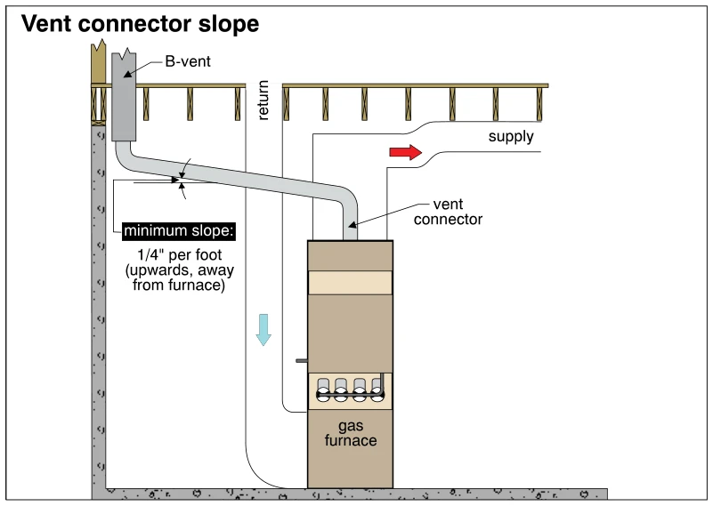
0767Vent connector slope
· p. 125
The illustration shows a gas furnace with a vent connector running from its top to a vertical B-vent near the foundation wall. The connector rises away from the furnace toward the B-vent, with a specified minimum slope of 1/4 inch per foot. Elbows connect the sloping run to the furnace outlet and vertical vent. Return and supply ductwork are also shown, with arrows indicating return air moving downward and supply air moving outward.
 0768
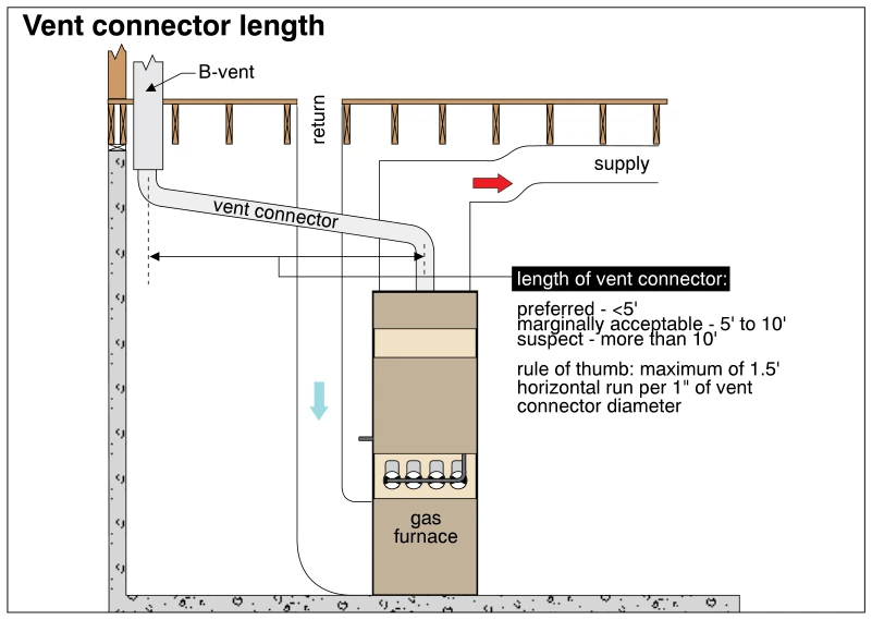
0768Vent connector length
· p. 125
The illustration shows a gas furnace with a vent connector rising from its top and extending upward toward a vertical B-vent at the left. A horizontal dimension line measures the connector's horizontal run between the furnace connection and the B-vent. The annotations classify lengths under 5 feet as preferred, 5 to 10 feet as marginally acceptable, and more than 10 feet as suspect. A stated rule of thumb limits horizontal run to 1.5 feet per inch of vent connector diameter. Supply and return ducts are also shown, with arrows indicating airflow.
 0769
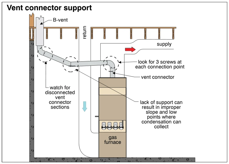
0769Vent connector support
· p. 125
The illustration shows a gas furnace with supply and return ductwork and a vent connector leading to a vertical B-vent. The connector runs from an elbow above the furnace toward the B-vent, with a sagging low section and no intermediate supports shown. Dashed circles highlight connector joints, with instructions to check for three screws at each connection and watch for disconnected sections. An annotation warns that inadequate support can create improper slope and low points where condensation collects.
 0770
0770Combustible clearances for vent connectors and B-vents
· p. 125
The illustration shows a gas furnace connected by a sloping vent connector to a vertical B-vent passing through wood floor framing. Return and supply ducts are shown alongside the furnace, with arrows indicating airflow. A cross-sectional inset shows the double-wall B-vent with a required 1-inch clearance to combustibles. A second inset shows a single-walled vent connector with a required 6-inch clearance to combustibles. The diagram distinguishes the combustible-clearance requirements for the two vent types rather than depicting a specific clearance defect.
 0771
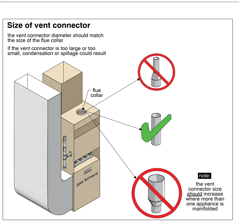
0771Size of vent connector
· p. 126
The illustration shows a gas furnace with adjacent ductwork and a flue collar on top of the cabinet. Arrows link the collar to three vent connector configurations: a reduced-diameter connector and an enlarged-diameter connector marked with red prohibition symbols, and a uniform-diameter connector marked with a green check. The annotations state that the connector diameter should match the flue collar and that an oversized or undersized connector could cause condensation or combustion-product spillage. A separate note states that vent connector size should increase where more than one appliance is manifolded.
 0772
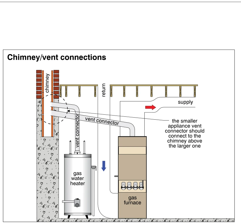
0772Chimney/vent connections
· p. 126
The illustration shows a gas furnace and a gas water heater connected by separate vent connectors to a common masonry chimney. The smaller water heater vent connector enters the chimney above the larger furnace vent connector, as directed by the annotation. The furnace vent connector slopes upward toward the chimney. Return and supply ductwork are shown beside and above the furnace, with arrows indicating airflow toward the furnace on the return side and away from it on the supply side.
 0773
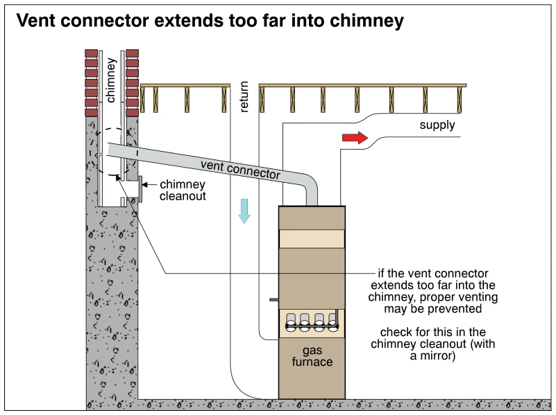
0773Vent connector extends too far into chimney
· p. 126
A sectional drawing shows a gas furnace connected to a masonry chimney by a sloping metal vent connector. The connector projects too far into the chimney flue, restricting the passage available for combustion exhaust and potentially preventing proper venting. A chimney cleanout is shown below the connector entry, with an annotation recommending checking the projection through the cleanout using a mirror. Return and supply ducts flank the furnace, with arrows indicating circulating airflow.
 0774
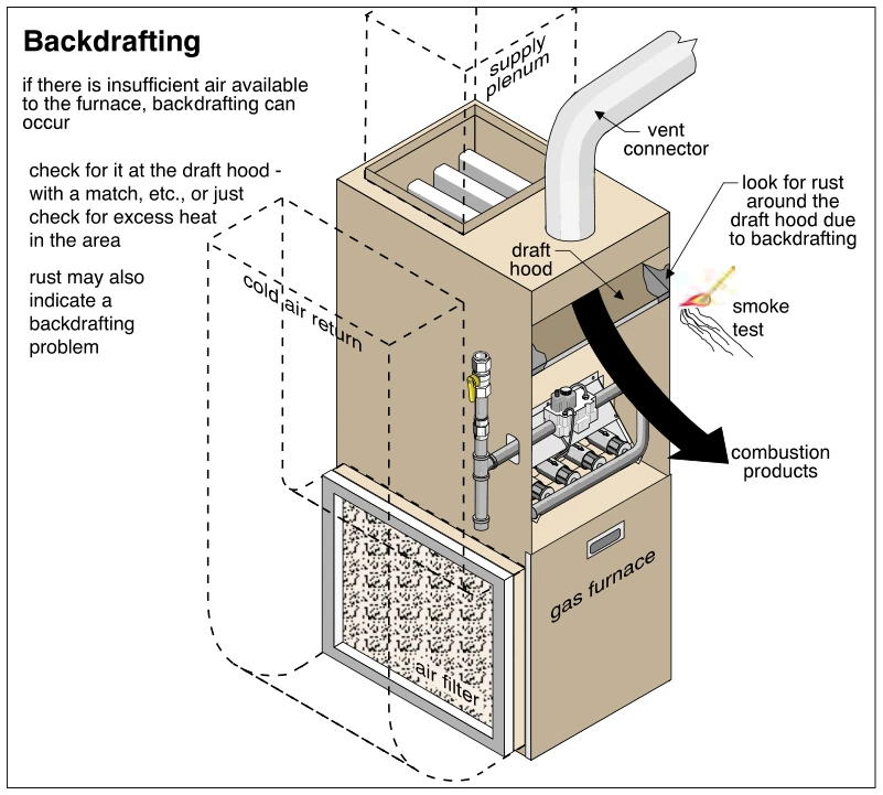
0774Backdrafting
· p. 126
The illustration depicts a gas furnace with an exposed burner compartment, draft hood, and vent connector rising from the top. Dashed outlines indicate the supply plenum and cold air return, with an air filter at the return opening. A large arrow shows combustion products spilling out of the draft hood into the surrounding space rather than exhausting through the vent connector. A hand holding a smoking match illustrates a draft check at the hood, and a callout identifies rust around the hood as a possible sign of backdrafting. The annotations explain that insufficient air available to the furnace can cause backdrafting and that excess heat near the hood may also indicate the problem.
Furnaces – Gas And Oil ·Distribution Systemp. 127
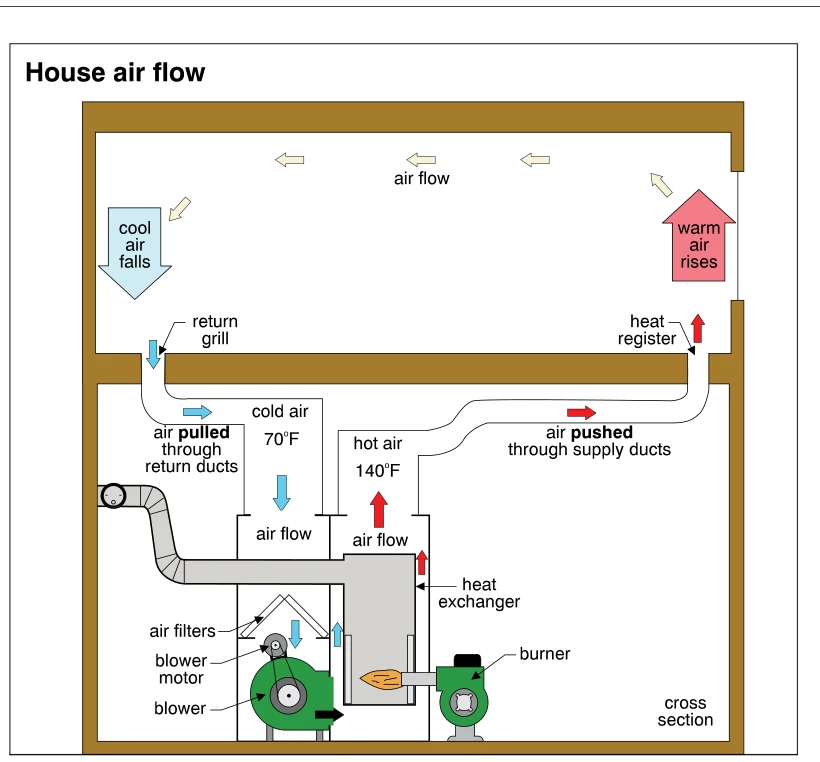 0775
0775House air flow
· p. 127
A cross section of a house illustrates a forced-air heating distribution system with a furnace below the occupied room. Cool air enters a floor-level return grille and travels through return ducts toward the furnace filters and motor-driven blower. The blower moves air past the heat exchanger, which is heated by a burner, and into supply ducts leading to a floor-level heat register. Arrows show warm air rising at the register, circulating across the room, and descending as it cools toward the return grille. Return air is labeled 70°F and heated supply air is labeled 140°F; a separate flue passage extends from the heat exchanger to the exterior.
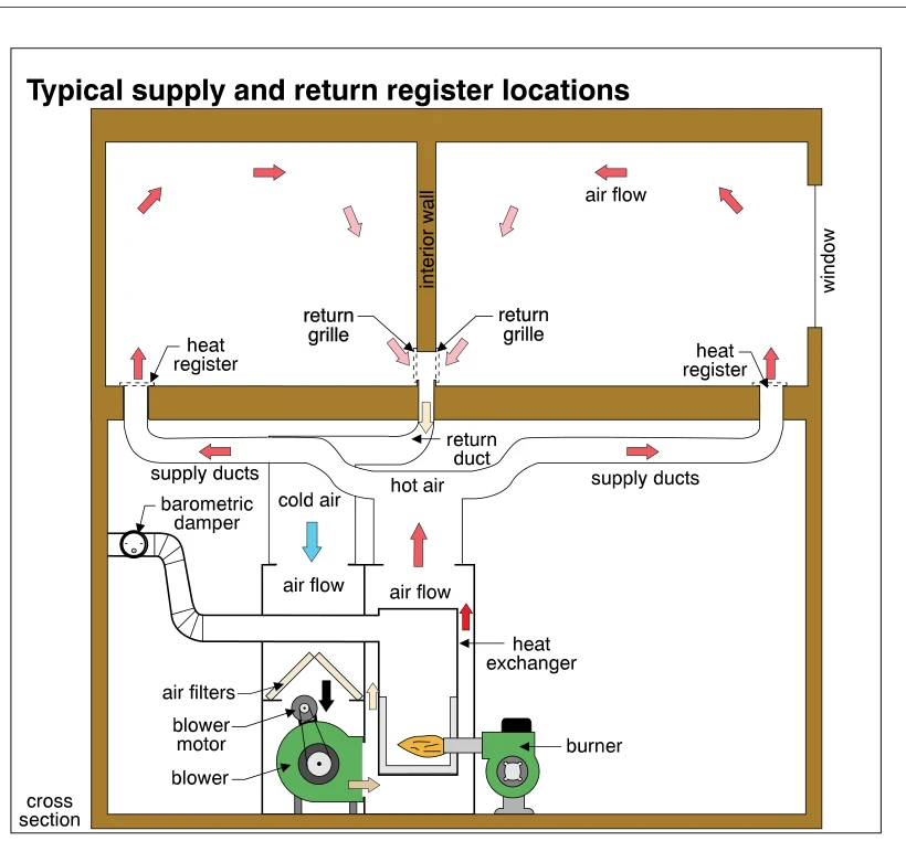 0776
0776Typical supply and return register locations
· p. 127
The cross-sectional diagram shows a forced-air furnace below two rooms, with supply ducts delivering heated air to registers at the exterior edges of the rooms. Return grilles near the central interior wall connect to a return duct that carries cooler air back to the furnace. Arrows illustrate air rising from the heat registers, circulating through the rooms, and descending toward the return grilles. Within the furnace, air passes through filters and a motor-driven blower before moving past the heat exchanger into the hot-air supply ductwork. A burner and a vent connector with a barometric damper are also shown.
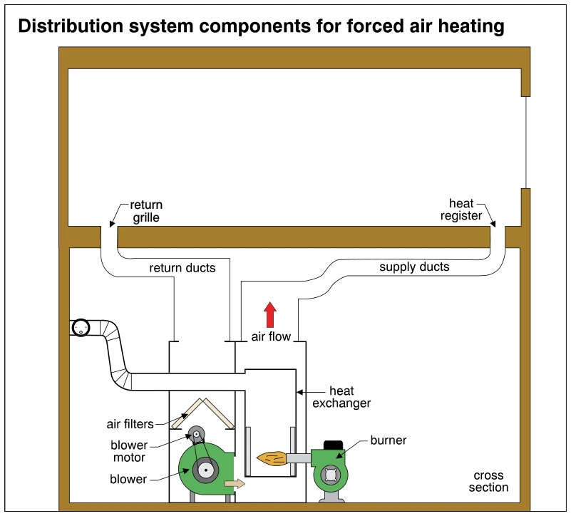 0777
0777Distribution system components for forced air heating
· p. 127
A cross-sectional schematic shows a forced-air furnace below a room, connected to return and supply ductwork. The return grille connects to ducts leading down to air filters and a motor-driven blower. The blower moves air through the furnace past the heat exchanger, with an upward arrow indicating airflow into the supply ducts. The supply ducts deliver heated air to a heat register on the opposite side of the room. A burner is shown firing into the heat exchanger, and a separate vent pipe extends from the furnace to the exterior wall.
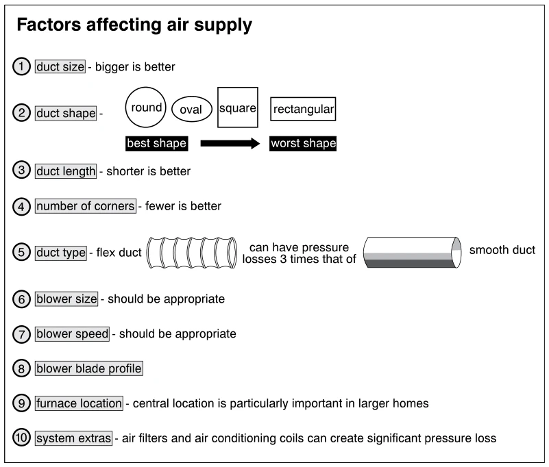 0778
0778Factors affecting air supply
· p. 127
The illustration lists ten factors affecting air supply in a forced-air heating distribution system. Duct cross sections are ranked from round as the best shape through oval and square to rectangular as the worst shape. A corrugated flexible duct is compared with a smooth duct, with an annotation stating that flex duct can have three times the pressure losses. The guidance favors larger, shorter ducts with fewer corners and appropriate blower size and speed, and identifies blower blade profile as another factor. It also emphasizes central furnace location in larger homes and notes the significant pressure loss that air filters and air conditioning coils can create.
Furnaces – Gas And Oil ·Air Filters and Cleanersp. 128
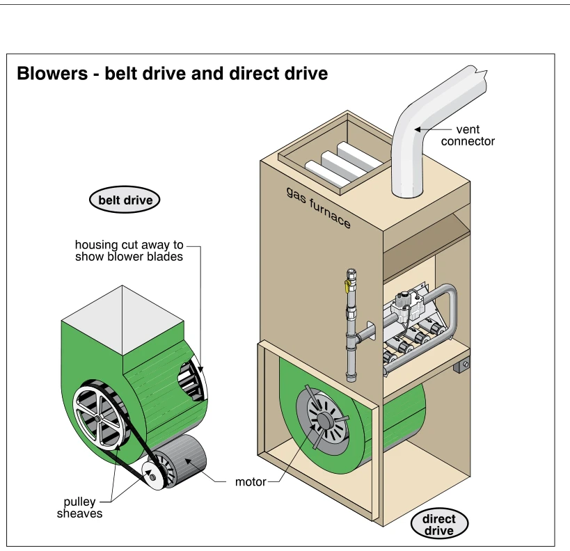 0779
0779Blowers - belt drive and direct drive
· p. 128
The illustration compares belt-drive and direct-drive centrifugal blowers for forced-air furnaces. The separate belt-drive assembly has an external motor connected to the blower by a belt running over pulley sheaves; a cutaway in the housing exposes the blower blades. The direct-drive blower is shown installed in the lower compartment of a gas furnace, with its motor mounted at the blower wheel axis and no external belt or pulleys. The furnace also shows burner components, gas piping, and a vent connector extending from the top. Neither arrangement is depicted as defective.
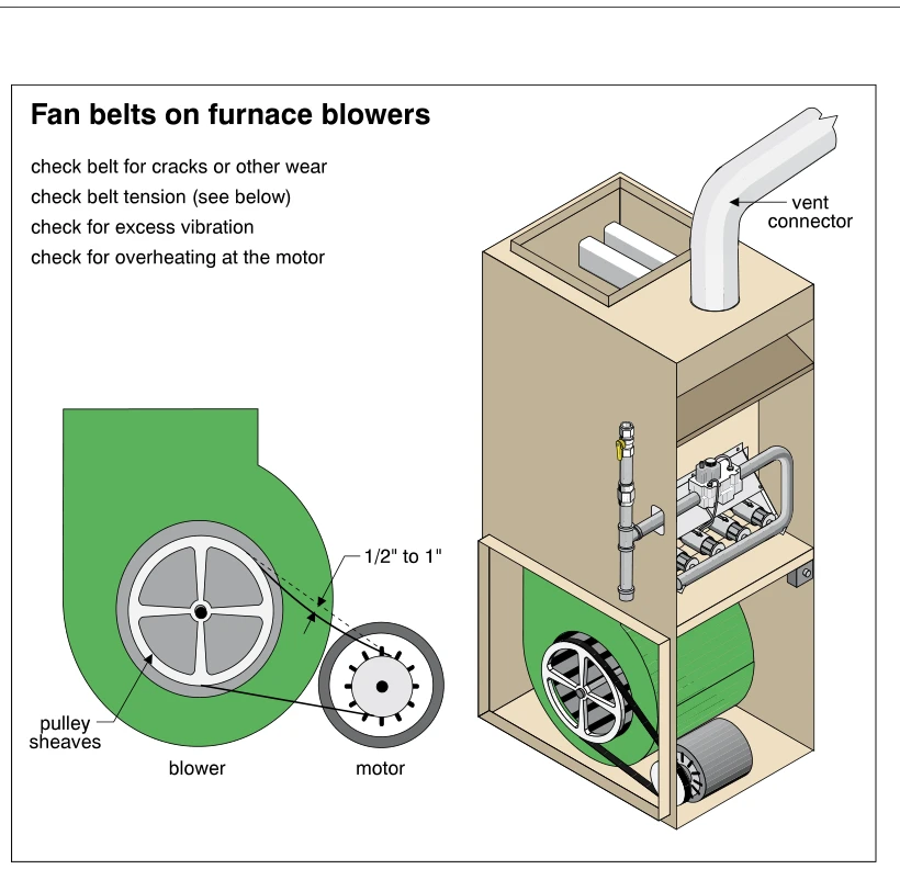 0780
0780Fan belts on furnace blowers
· p. 128
The illustration shows a furnace with open front compartments exposing the burner assembly above a belt-driven blower and motor. A vent connector exits the top of the furnace. An enlarged detail shows a belt connecting the small motor pulley to the larger blower pulley, with a deflection dimension of 1/2 inch to 1 inch indicated between the pulleys. Inspection annotations direct the reader to check belt wear and tension, excess vibration, and motor overheating; no specific damage is illustrated.
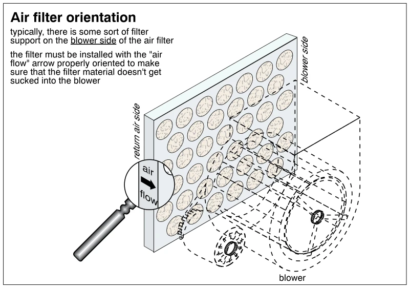 0781
0781Air filter orientation
· p. 128
The illustration shows a rectangular air filter positioned on the return-air side of a forced-air heating blower, with the blower drawn in dashed outline. A perforated support face is shown on the blower side of the filter. A magnified view highlights the filter's edge marking, with the air-flow arrow pointing toward the blower. The annotations explain that correct orientation keeps the filter material from being sucked into the blower.
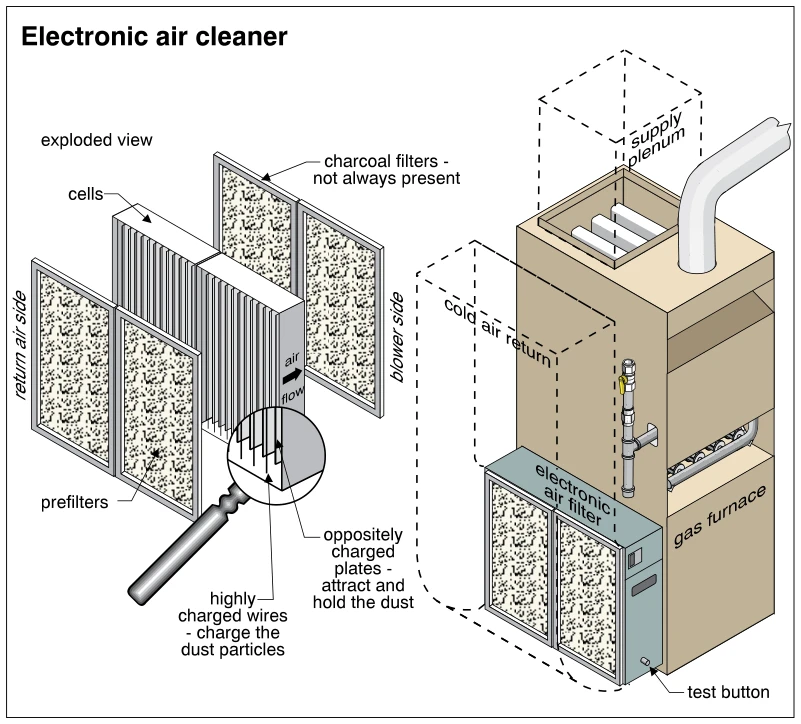 0782
0782Electronic air cleaner
· p. 128
The illustration shows an electronic air cleaner installed in the cold-air return beside a gas furnace, with the supply plenum indicated above the furnace. An exploded view shows prefilters on the return-air side, electronic cells in the middle, and optional charcoal filters on the blower side. An airflow arrow indicates movement through the cells toward the blower. A magnified detail explains that highly charged wires charge dust particles and oppositely charged plates attract and hold the dust. A test button is identified near the bottom of the installed cleaner cabinet.
Furnaces – Gas And Oil ·Humidifiersp. 129
 0783
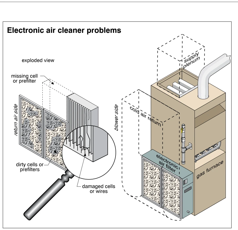
0783Electronic air cleaner problems
· p. 129
The illustration shows an electronic air cleaner installed in the cold-air return beside a gas furnace, with the supply plenum above the furnace. An exploded view shows the cleaner's prefilters and collecting cell between the return-air side and the blower side. A dashed outline identifies a missing cell or prefilter, and dark deposits indicate dirty cells or prefilters. A magnified detail highlights damaged cells or wires within the collecting assembly.
 0784
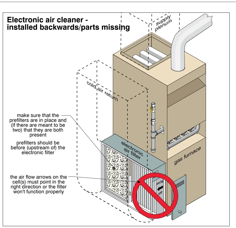
0784Electronic air cleaner - installed backwards/parts missing
· p. 129
The illustration shows an electronic air cleaner installed at the cold-air return connection to a gas furnace, with the supply plenum indicated above the furnace. The cleaner is opened to expose a mesh prefilter and a plate-type electronic filter cell. An airflow arrow on the cell and a red prohibition symbol highlight improper cell orientation. Annotations explain that all required prefilters must be present upstream of the electronic filter and that the cell airflow arrows must point in the correct direction for proper operation.
 0785
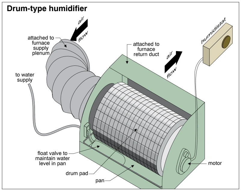
0785Drum-type humidifier
· p. 129
The cutaway illustration shows a drum-type humidifier attached to a furnace return duct and connected by a round bypass duct to the furnace supply plenum. Airflow arrows indicate air entering through the supply-side connection and leaving toward the return duct. A cylindrical drum pad sits above a water pan, with its lower portion extending into the pan. A water supply line feeds a float valve that maintains the pan's water level. A side-mounted motor drives the drum, and a humidistat is shown connected to the unit.
 0786
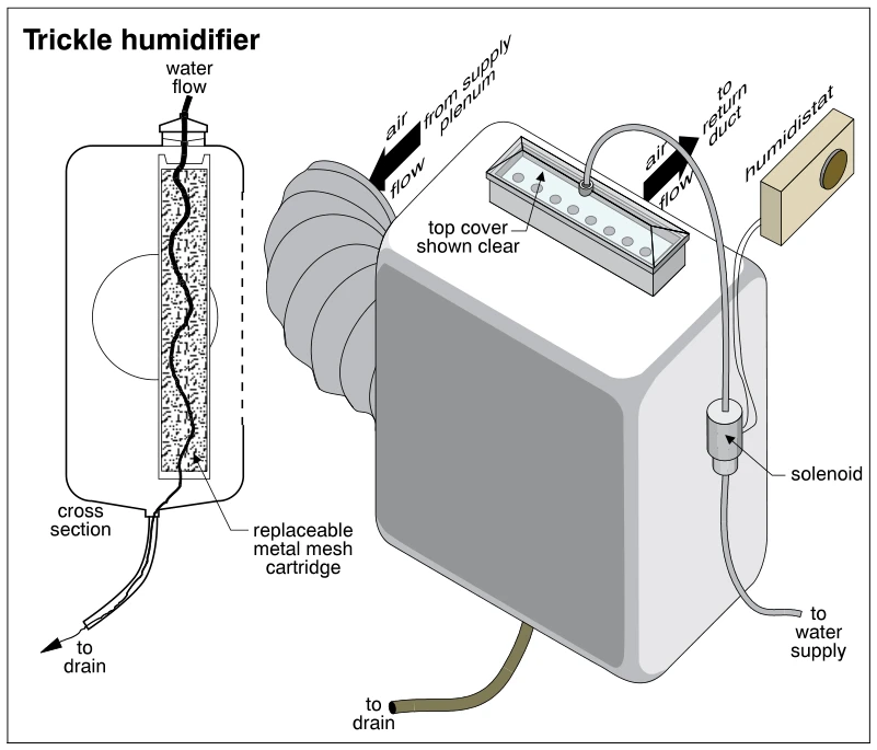
0786Trickle humidifier
· p. 129
The illustration shows a trickle-type humidifier for a forced-air heating system, with airflow indicated from the supply plenum through the unit toward the return duct. A water supply tube feeds a perforated distribution tray at the top, whose cover is shown clear. A separate cross section shows water trickling down a replaceable metal mesh cartridge and leaving through a drain at the bottom. A humidistat is connected to the solenoid on the water supply line. No defects or improper installation practices are indicated.
Duct Systems, Registers and Grillesp. 130
 0787
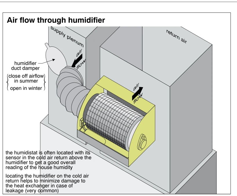
0787Air flow through humidifier
· p. 130
The illustration shows a drum-style bypass humidifier mounted on the cold-air return of a forced-air heating system. A flexible bypass duct connects the supply plenum to the humidifier, with arrows showing airflow from the supply through the humidifier into the return. The open humidifier housing exposes a cylindrical mesh-covered drum and a lower reservoir. A duct damper is labeled to close off airflow in summer and remain open in winter. Notes describe locating the humidistat sensor in the return above the humidifier and explain that return-side humidifier installation helps minimize heat-exchanger damage in the event of leakage.
 0788
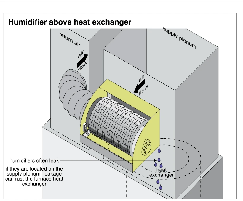
0788Humidifier above heat exchanger
· p. 130
The illustration shows a drum-type humidifier mounted on a forced-air furnace supply plenum above the heat exchanger. A flexible bypass duct connects the humidifier to the adjacent return-air duct, with arrows indicating airflow. The humidifier housing is cut away to expose the cylindrical drum and lower water reservoir. Water droplets descend from the humidifier toward the heat exchanger, which is outlined with dashed lines. The annotations warn that leakage from a humidifier in this location can rust the furnace heat exchanger.
 0789
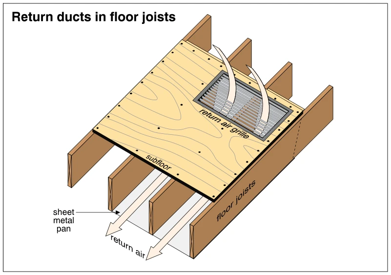
0789Return ducts in floor joists
· p. 130
The illustration shows a floor-mounted return air grille set into a wood subfloor supported by floor joists. A sheet metal pan closes the underside of the joist spaces to form return air passages. Arrows show air entering through the grille and traveling along the enclosed joist spaces. The cutaway illustrates a panned-joist return arrangement for a forced-air heating system; no furnace or specific defect is shown.
 0790
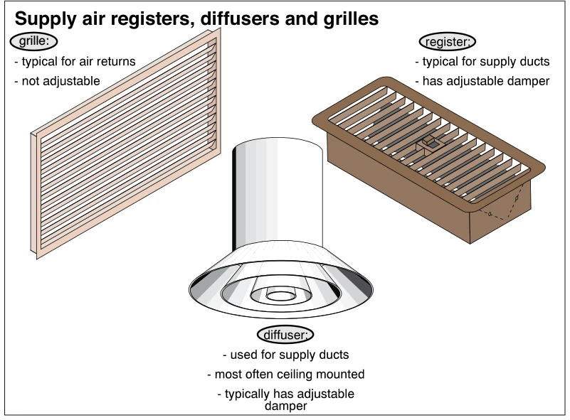
0790Supply air registers, diffusers and grilles
· p. 130
The illustration identifies three types of forced-air duct outlets and inlets: a grille, a register, and a diffuser. The rectangular grille has fixed parallel slats and is identified as typical for air returns and not adjustable. The rectangular supply register has parallel slats and an adjustable damper with a visible control. The circular diffuser connects to a round duct neck and has concentric air-distribution rings; its annotations identify it as typically ceiling mounted, used for supply ducts, and usually equipped with an adjustable damper. No defects or installation failures are depicted.
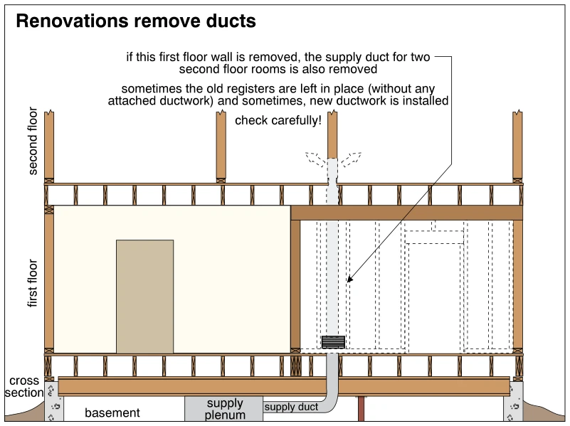 0791
0791Renovations remove ducts
· p. 130
A cross section of a two-story house shows a basement supply plenum and supply duct serving a vertical duct route within a first-floor wall. Dashed lines indicate the wall framing and duct route in the area opened during renovation. Removing this wall also removes the supply duct serving two second-floor rooms. The annotations warn that existing registers may remain without attached ductwork, although replacement ductwork is sometimes installed, and call for careful inspection.
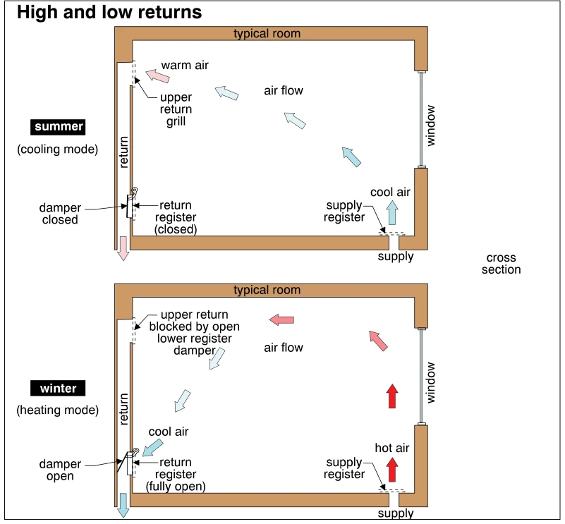 0792
0792High and low returns
· p. 130
Two room cross sections illustrate seasonal operation of high and low returns in a forced-air distribution system. Both show a floor supply register beneath a window and a return duct on the opposite wall with upper and lower openings. In summer cooling mode, the lower return register damper is closed, directing warm room air into the upper return grille while cool air enters through the supply register. In winter heating mode, the lower register damper is fully open and blocks the return path from the upper opening, allowing cool air near the floor to enter the return. Arrows show supply air rising and circulating across the room toward the selected return opening.
Mid- and High-Efficiency Furnacesp. 131
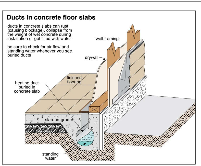 0793
0793Ducts in concrete floor slabs
· p. 131
A cutaway shows a heating duct buried in a concrete slab-on-grade beside a framed exterior wall. The round duct connects to a vertical branch terminating at floor level near the wall. Standing water is visible in the buried duct beneath the finished flooring. Annotations warn that embedded ducts can rust and become blocked, collapse under the weight of wet concrete during installation, or fill with water. The illustration advises checking buried ducts for airflow and standing water.
 0794
0794Supply and return registers poorly located
· p. 131
The illustration shows a room with a floor-mounted heat register beside an interior wall and doorway, and a floor-mounted return air grille beside the exterior wall below a window. Arrows identify the interior side of the room as warmer and the exterior side as cooler. The arrangement illustrates poorly located supply and return openings that contribute to uneven room temperatures and reduced comfort. An annotation states that these locations should be noted and that auxiliary electric heat may be desirable.
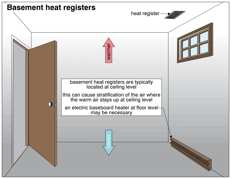 0795
0795Basement heat registers
· p. 131
The illustration shows a basement room with a forced-air heat register in the ceiling and an electric baseboard heater along the bottom of a wall. An upward arrow marked “warmer” and a downward arrow marked “cooler” depict temperature stratification. The annotation explains that ceiling-level basement registers can leave warm air near the ceiling rather than heating the occupied area evenly. A callout to the baseboard heater identifies floor-level supplemental electric heat as potentially necessary.
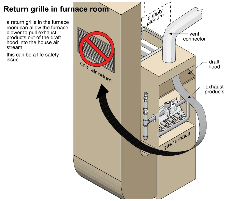 0796
0796Return grille in furnace room
· p. 131
The illustration shows a gas furnace beside a cold-air return duct with a return grille opening into the furnace room. A red prohibition symbol marks the grille as improper. The furnace has an exposed burner assembly, a draft hood, and a vent connector above it, with a supply plenum behind. Curved arrows illustrate exhaust products being drawn out of the draft hood and into the return grille by the furnace blower. The annotation identifies contamination of the house air stream with furnace exhaust as a potential life-safety issue.
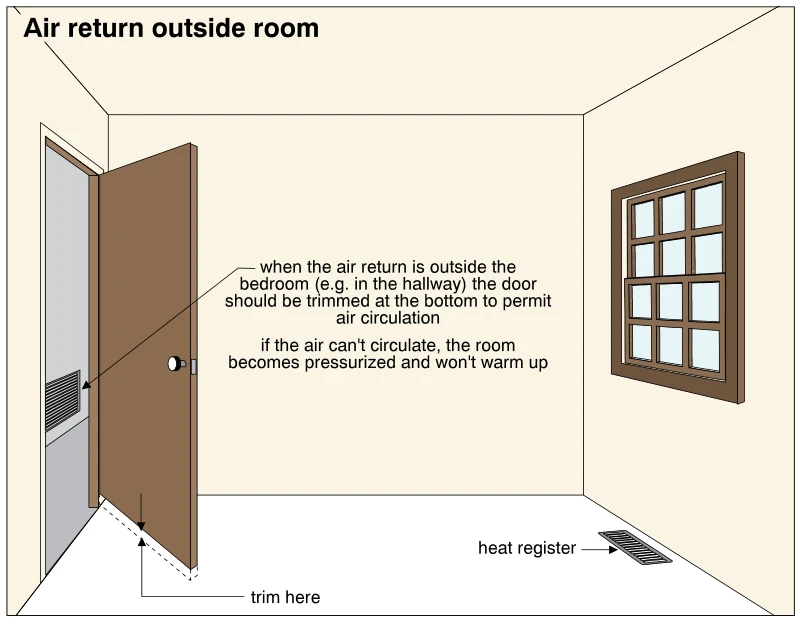 0797
0797Air return outside room
· p. 131
The illustration shows a bedroom with a floor-mounted heat register and a return-air grille outside the room, visible through the open doorway. An arrow and dashed line at the door bottom indicate where to trim the door to provide an air-transfer gap. This undercut allows air supplied to the bedroom to reach the hallway return when the door is closed. The annotation warns that without adequate circulation, the room becomes pressurized and will not warm up properly.
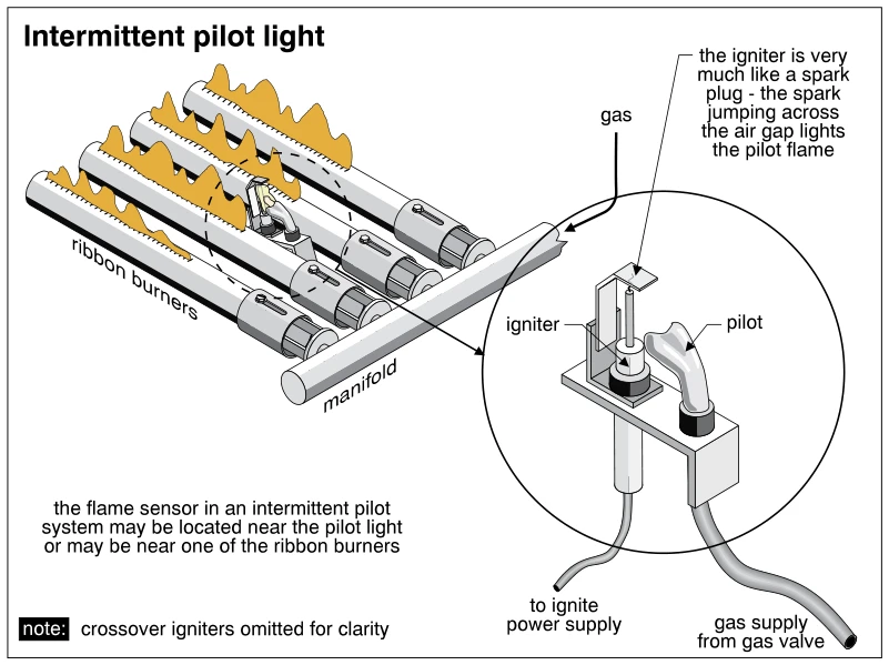 0798
0798Intermittent pilot light
· p. 131
The illustration shows a gas furnace burner assembly with a common gas manifold feeding four ribbon burners, with flames along their tops. A circular enlargement details the intermittent pilot and adjacent spark igniter mounted on a bracket. The igniter connects to a power supply, while the pilot receives gas through tubing from the gas valve. An annotation explains that a spark across the igniter air gap lights the pilot flame. Additional notes identify possible flame-sensor locations near the pilot or a ribbon burner and state that crossover igniters are omitted for clarity.
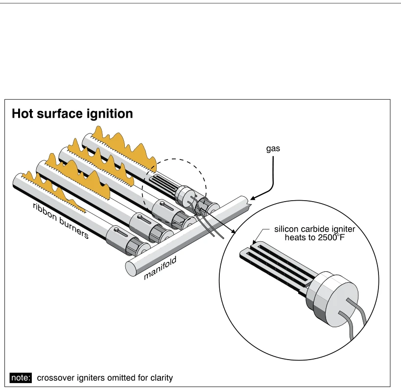 0799
0799Hot surface ignition
· p. 132
The illustration shows a gas furnace ribbon-burner assembly supplied by a common gas manifold, with flames along the burners. A hot-surface igniter is positioned beside one burner and highlighted with a magnified detail. The detail shows the slotted silicon carbide igniter element, its base, and two electrical leads; the annotation states that it heats to 2500°F. A note indicates that crossover igniters are omitted for clarity.
 0800
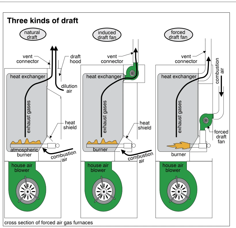
0800Three kinds of draft
· p. 132
Three cross-sectional diagrams compare natural, induced, and forced draft in forced-air gas furnaces. Each furnace has a burner beneath a heat exchanger, a vent connector above, and a separate house air blower below. The natural-draft furnace shows an atmospheric burner and a draft hood admitting dilution air into the exhaust path. The induced-draft arrangement places a fan at the heat exchanger outlet to draw exhaust gases toward the vent connector. The forced-draft arrangement places a fan on the combustion-air inlet to push air toward the burner, with exhaust gases leaving through the upper vent connector.
 0801
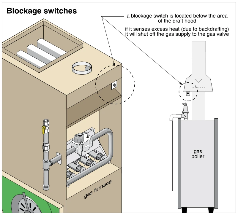
0801Blockage switches
· p. 132
The illustration shows a cutaway gas furnace and a schematic gas boiler, with blockage-switch locations highlighted by dashed circles and arrows. Each switch is positioned below the draft hood area. The furnace view exposes the burners, gas valve, gas piping, and part of the blower compartment. The annotation explains that excess heat caused by backdrafting triggers the blockage switch to shut off the gas supply to the gas valve.
 0802
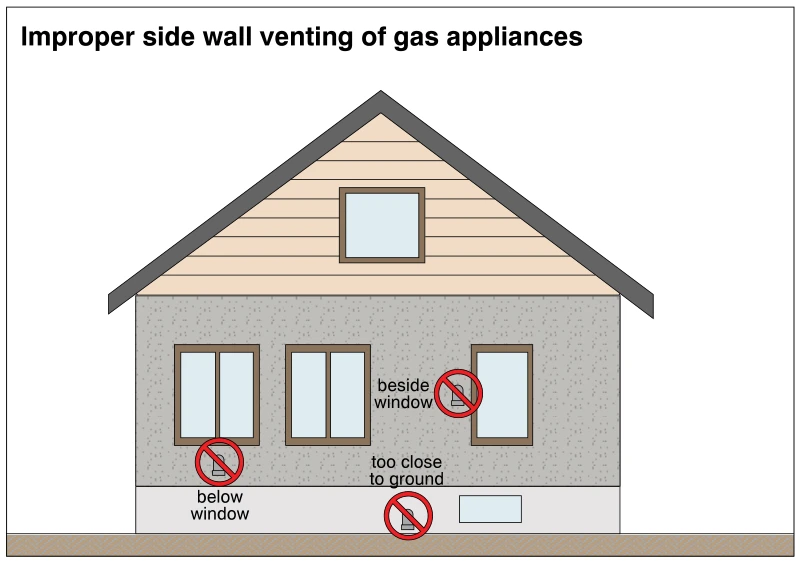
0802Improper side wall venting of gas appliances
· p. 132
The illustration shows a house exterior with three improper locations for gas-appliance sidewall vent terminations. Red prohibition symbols mark a vent beside a window, a vent below a window, and a vent near ground level. The drawing emphasizes clearance problems relative to windows and finished grade. No clearance dimensions or interior appliance connections are shown.
 0803
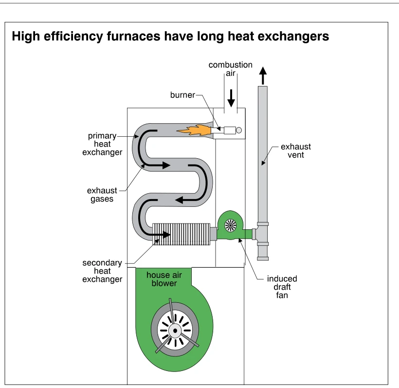
0803High efficiency furnaces have long heat exchangers
· p. 133
The illustration shows a schematic cutaway of a high-efficiency gas furnace with a long, serpentine primary heat exchanger and a secondary heat exchanger below it. Combustion air enters from above at the burner, whose flame projects into the primary heat exchanger. Arrows trace exhaust gases through the winding primary exchanger, through the secondary exchanger, and toward an induced draft fan. The fan connects to a vertical exhaust vent with an upward discharge arrow. A separate house air blower occupies the lower furnace compartment; no defects or improper installation practices are indicated.
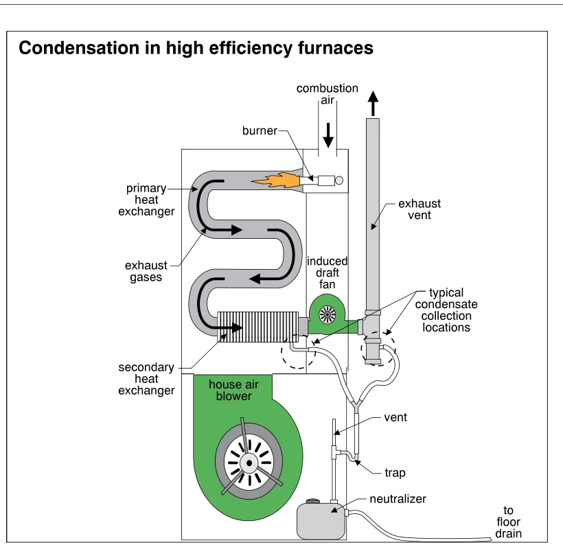 0804
0804Condensation in high efficiency furnaces
· p. 133
The schematic depicts a high-efficiency condensing gas furnace with a burner, primary and secondary heat exchangers, and a house air blower. Arrows show combustion air entering above the burner and exhaust gases passing through the heat exchangers to an induced draft fan and vertical exhaust vent. Dashed circles identify typical condensate collection locations near the secondary heat exchanger outlet and the base of the exhaust vent. Drain lines from these locations join and pass through a vented trap arrangement to a neutralizer, with discharge directed to a floor drain.
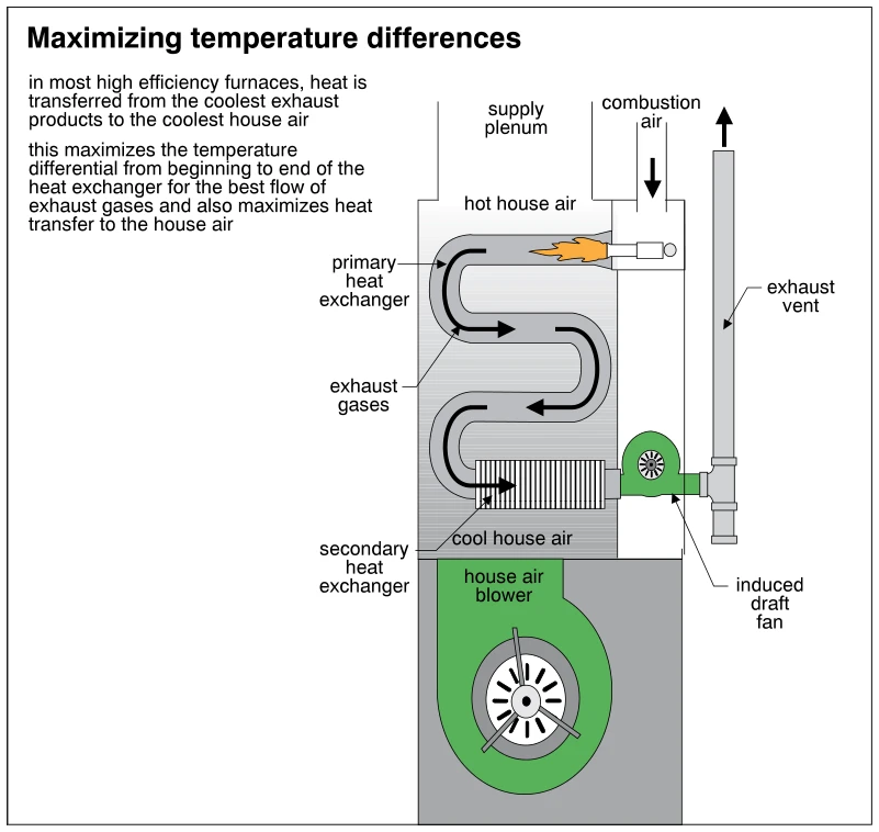 0805
0805Maximizing temperature differences
· p. 133
The illustration shows a high-efficiency gas furnace with a burner, serpentine primary heat exchanger, secondary heat exchanger, and house air blower below. Arrows trace combustion gases through the primary exchanger and then through the secondary exchanger to an induced draft fan and exhaust vent. Cool house air encounters the secondary heat exchanger first, then passes upward over the primary exchanger toward the hot-air supply plenum. This arrangement places the coolest exhaust products next to the coolest house air to maximize temperature differences and heat transfer along the heat exchanger path. A separate downward arrow identifies combustion air entering near the burner.
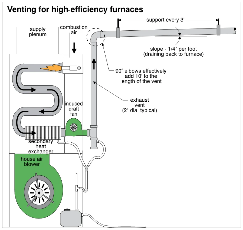 0806
0806Venting for high-efficiency furnaces
· p. 133
The illustration shows a cutaway of a high-efficiency condensing gas furnace with a burner, heat exchangers, house air blower, and induced draft fan. Arrows trace combustion gases through the heat exchanger assembly and upward into the exhaust vent. The vent rises vertically, turns through a 90° elbow, and runs at a specified slope of 1/4 inch per foot to drain condensate back toward the furnace. Annotations specify supports every 3 feet, a typical exhaust vent diameter of 2 inches, and an effective vent-length allowance of 10 feet for a 90° elbow. Condensate tubing from the furnace and vent connects to a drain arrangement and a small collection unit at the base.
Condensing Furnacesp. 134
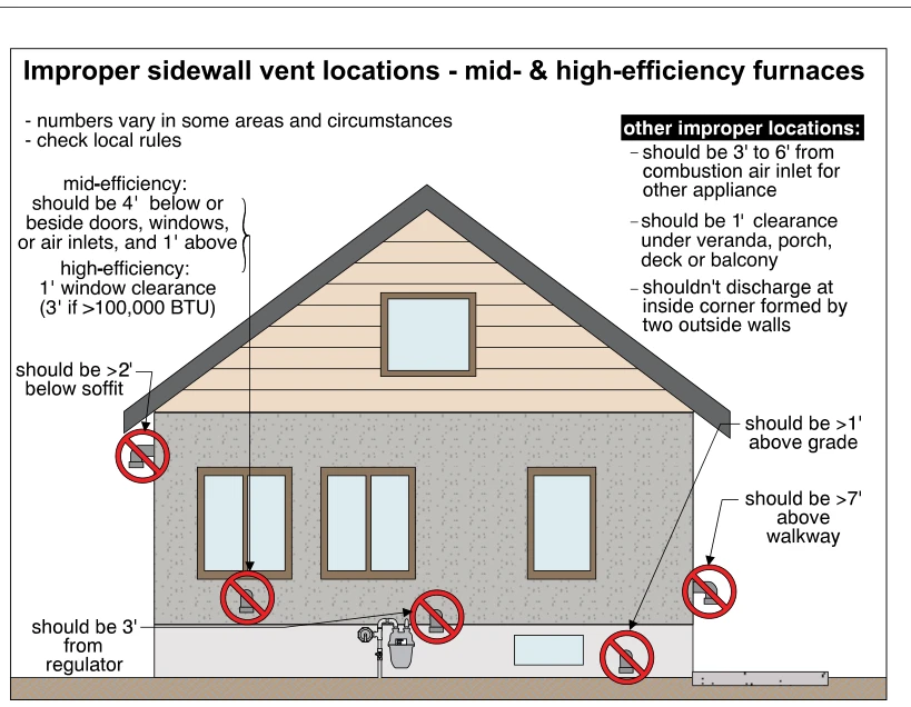 0807
0807Improper sidewall vent locations - mid- & high-efficiency furnaces
· p. 134
The illustration shows a house elevation with five sidewall furnace vent terminations marked by red prohibition symbols. Improper locations include a termination close below the soffit, one directly below a window, one near the gas regulator, one close to grade, and one too low above a walkway. Callouts give clearance guidance for mid- and high-efficiency furnaces, including different clearances around windows and other openings. Additional annotations address separation from another appliance's combustion air inlet, clearance beneath porches and decks, and avoiding discharge into an inside corner between exterior walls. The drawing notes that requirements vary by location and circumstances and directs readers to check local rules.
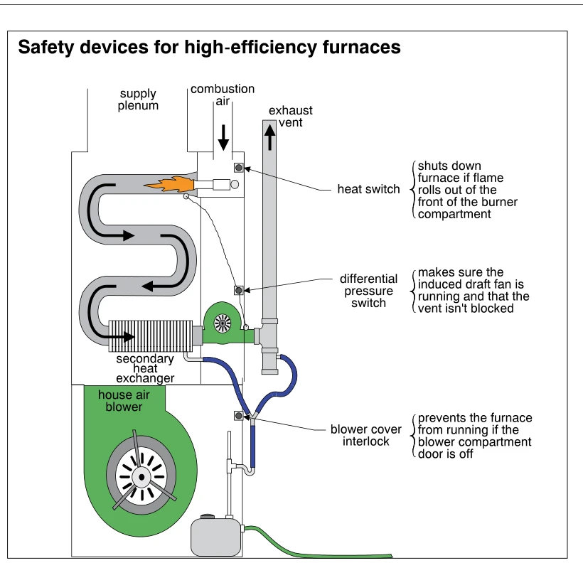 0808
0808Safety devices for high-efficiency furnaces
· p. 134
The illustration shows a cutaway schematic of a high-efficiency condensing gas furnace with a burner, serpentine heat exchanger, secondary heat exchanger, induced draft fan, and house air blower. Arrows indicate combustion air entering from above and combustion products passing through the heat exchangers toward the exhaust vent. A heat switch near the burner shuts down the furnace if flame rolls out of the burner compartment. A differential pressure switch checks induced draft operation and whether the vent is blocked. A blower cover interlock prevents operation with the blower compartment door removed, and condensate tubing is depicted below the heat exchanger and vent assembly.
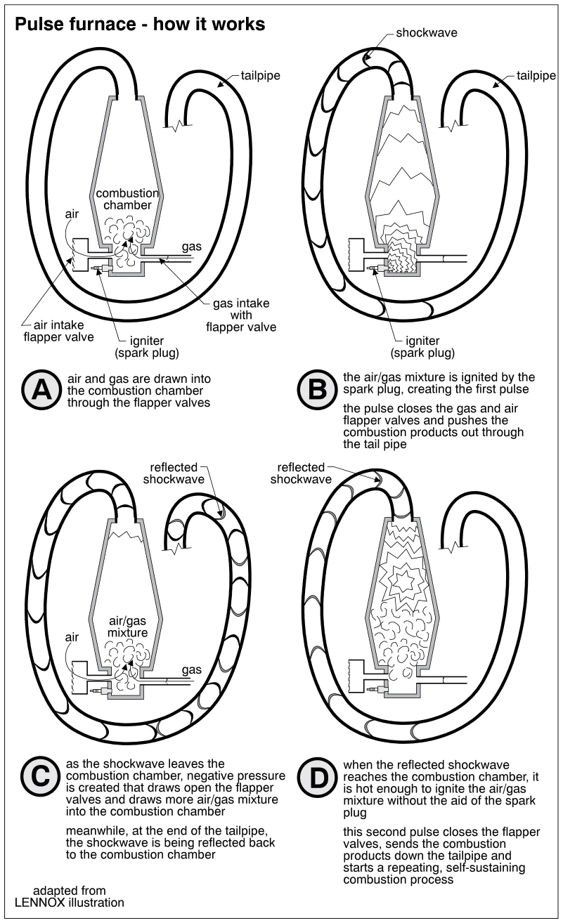 0809
0809Pulse furnace - how it works
· p. 134
Four schematic stages show the operating cycle of a pulse gas furnace, with a combustion chamber connected to a long, looping tailpipe. In stage A, air and gas enter through flapper valves near the spark-plug igniter at the base of the chamber. In stage B, spark ignition produces a pressure pulse that closes the inlet valves and drives combustion products into the tailpipe. Stage C shows the departing shockwave creating negative pressure that opens the valves to admit a fresh air/gas mixture, while the wave reflects from the tailpipe end. In stage D, the returning hot shockwave ignites the fresh mixture without the spark plug, establishing a repeating, self-sustaining combustion cycle.
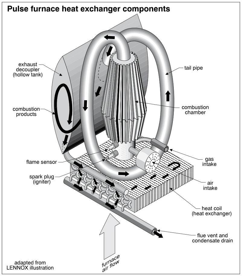 0810
0810Pulse furnace heat exchanger components
· p. 134
The illustration shows the heat exchanger assembly of a pulse-type condensing gas furnace. A finned combustion chamber connects to a looping tail pipe, with gas and air intakes, a flame sensor, and a spark plug identified near its base. An exhaust decoupler is shown as a hollow tank behind the combustion chamber, and arrows indicate the movement of combustion products through the assembly. A finned heat coil beneath the chamber leads to a labeled flue vent and condensate drain. A large upward arrow shows furnace air flowing across the heat exchanger assembly; no defects are depicted.
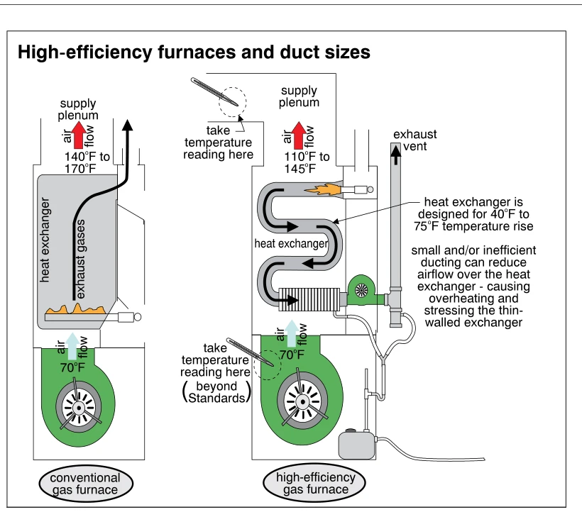 0811
0811High-efficiency furnaces and duct sizes
· p. 135
Side-by-side cutaways compare a conventional gas furnace with a high-efficiency gas furnace, showing burners, heat exchangers, blowers, supply plenums, and exhaust paths. Both units show entering air at 70°F; supply air is labeled 140°F to 170°F for the conventional furnace and 110°F to 145°F for the high-efficiency furnace. The high-efficiency unit has a winding heat-exchanger path, an exhaust blower and vent, and condensate tubing leading to a collection unit below. Temperature-reading locations are indicated above and below its heat exchanger. An annotation specifies a 40°F to 75°F design temperature rise and warns that small or inefficient ducting can restrict airflow, overheat the furnace, and stress the thin-walled heat exchanger.
 0812
0812Automatic vent dampers
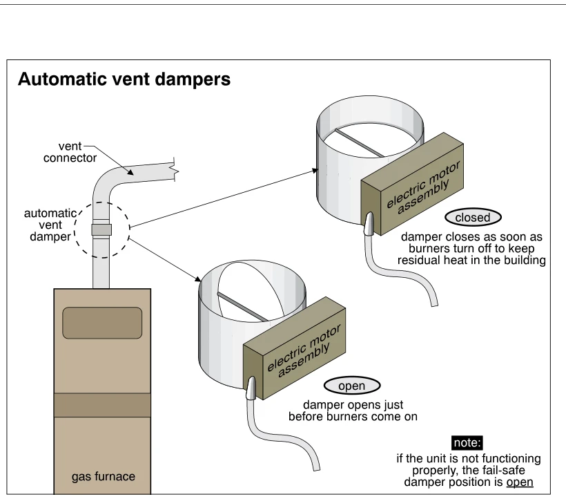
· p. 135
The illustration shows an automatic vent damper installed in the vent connector above a gas furnace. Two enlarged views show the damper plate in closed and open positions, operated by an external electric motor assembly. The damper closes as soon as the burners turn off to retain residual heat in the building and opens just before the burners come on. A note identifies open as the fail-safe damper position if the unit is not functioning properly.
 0813
0813Inspecting high-efficiency furnaces
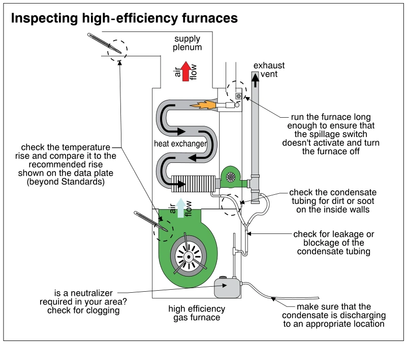
· p. 135
A cutaway schematic of a high-efficiency condensing gas furnace shows a lower circulating-air blower moving air upward past the heat exchangers into the supply plenum. A burner, serpentine heat exchanger, lower finned exchanger, induced-draft fan, and vertical exhaust vent illustrate the combustion-gas path. Thermometers at the lower air inlet and supply plenum indicate locations for checking temperature rise against the data plate. Condensate tubing leads from the furnace and vent area to a lower collection or treatment container and an outgoing drain line. Annotations identify inspection checks for spillage-switch shutdown, dirty or sooty condensate tubing, leakage, blockage, neutralizer requirements, and appropriate condensate discharge; no actual failure is explicitly shown.
 0814
0814Inspecting high-efficiency furnaces
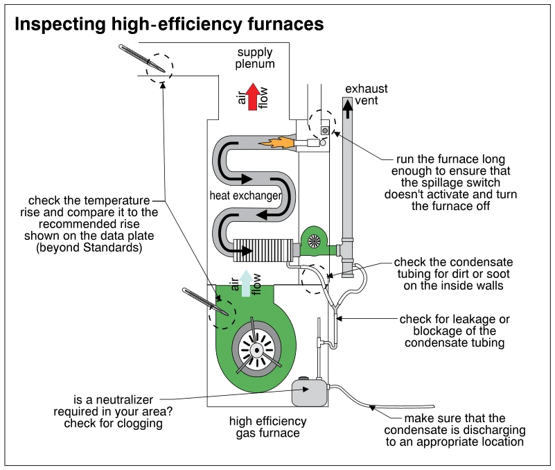
· p. 135
A cutaway schematic of a high-efficiency condensing gas furnace shows a burner, heat exchanger assembly, circulating blower, exhaust vent, and condensate drainage tubing. Arrows trace combustion gases through the heat exchanger and upward through the exhaust vent, while circulating air moves upward toward the supply plenum. Thermometers at the lower air inlet and supply plenum illustrate checking temperature rise against the furnace data plate. Annotations direct the inspector to run the furnace long enough to check for spillage-switch shutdown and inspect condensate tubing for dirt, soot, leaks, and blockages. The drawing also calls for checking whether a neutralizer is required, checking for clogging, and verifying an appropriate condensate discharge location; no actual failure is illustrated.
Combination Furnacesp. 136
 0815
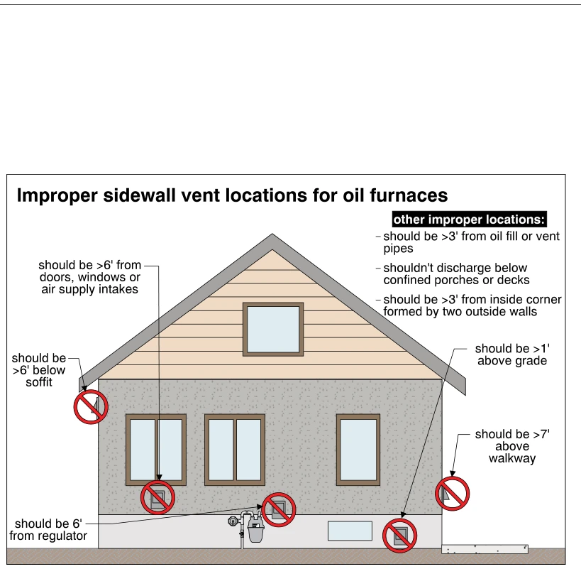
0815Improper sidewall vent locations for oil furnaces
· p. 136
The illustration shows a house elevation with prohibited oil-furnace sidewall vent locations marked by red prohibition symbols. Improper terminations are depicted near a soffit, beneath a window, near a regulator, close to grade, and beside a walkway. Callouts specify the illustrated separation distances from openings, soffits, the regulator, grade, and walkways. Additional notes address clearance from oil fill or vent pipes and inside corners, and prohibit discharge beneath confined porches or decks.
 0816
0816Venting for high-efficiency furnaces
· p. 136
A cutaway schematic shows a high-efficiency condensing gas furnace with a burner, serpentine heat exchanger, secondary heat exchanger, induced draft fan, and house-air blower beneath the supply plenum. Arrows trace combustion gases through the heat exchangers and upward into the exhaust vent. The vent turns through a 90-degree elbow into a horizontal run supported every 3 feet and sloped 1/4 inch per foot to drain back toward the furnace. An annotation states that 90-degree elbows effectively add 10 feet to the vent length, and the exhaust vent is labeled as typically 2 inches in diameter. Condensate tubing from the furnace and vent connects to a drain assembly and a small collection unit at the base.
 0817
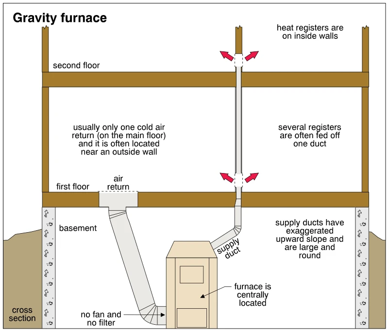
0817Gravity furnace
· p. 136
A house cross section shows a centrally located gravity furnace in the basement serving two floors. A large return duct descends from a first-floor air return near an outside wall to the base of the furnace. A supply duct slopes upward from the furnace and rises through an interior wall, feeding heat registers on both floors; red arrows indicate warm air discharge. Annotations identify large, round, upward-sloping supply ducts and the absence of a fan and filter. The illustration presents the typical layout of a gravity warm-air heating system rather than a defect.
 0818
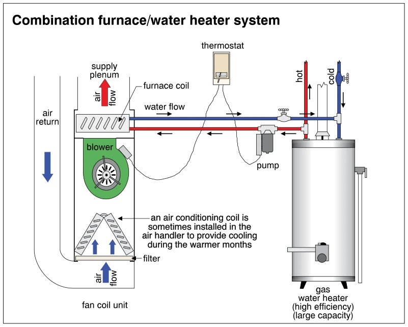
0818Combination furnace/water heater system
· p. 136
The diagram shows a combination space-heating and domestic hot-water system using a large-capacity, high-efficiency gas water heater connected to a fan coil unit. A pump circulates heated water from the tank through the furnace coil, with arrows indicating the supply and return water paths. Return air enters the bottom of the air handler through a filter, passes the optional air-conditioning coil and blower, and flows through the heating coil into the supply plenum. A thermostat is shown with control wiring to the blower and pump. The water heater also has labeled cold-water inlet and hot-water outlet connections.
Oil Furnacesp. 137
 0819
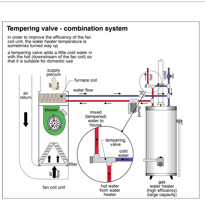
0819Tempering valve - combination system
· p. 137
The illustration shows a combination space-heating and domestic hot-water system using a gas water heater connected to a fan coil unit. A pump circulates water through the furnace coil, while a blower moves return air through a filter and upward across the coil into the supply plenum. Arrows indicate water and air flow directions. An enlarged detail shows a tempering valve mixing cold water with hot water to deliver tempered water to the house. The annotations explain that the water heater temperature may be raised to improve fan coil performance, with the tempering valve making the domestic water suitable for use.
 0820
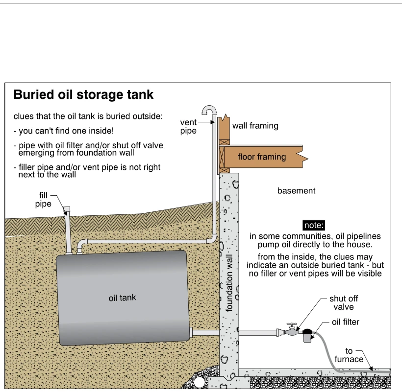
0820Buried oil storage tank
· p. 137
A sectional drawing shows an oil storage tank buried outside a basement foundation wall. A fill pipe rises from the tank to just above grade, while a separate vent pipe extends upward beside the house wall. An oil supply line passes through the foundation wall and connects to a shutoff valve and oil filter inside the basement before continuing toward the furnace. Annotations identify clues to a buried tank, including the absence of an indoor tank and an oil line emerging through the foundation. A note explains that community oil pipelines may produce similar indoor clues without visible exterior fill or vent pipes.
 0821
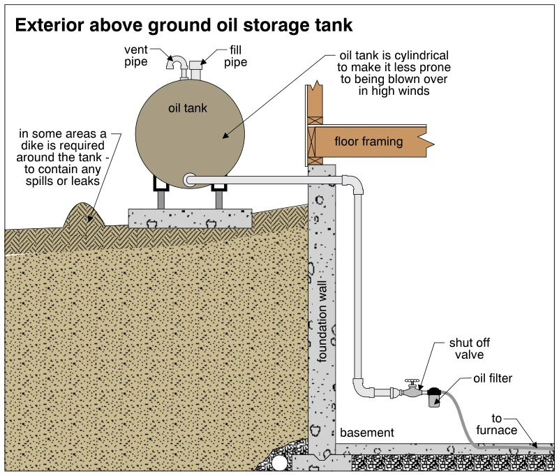
0821Exterior above ground oil storage tank
· p. 137
The illustration shows a cylindrical exterior above-ground oil storage tank supported on legs on a concrete pad beside a house foundation. Fill and vent pipes extend from the top of the tank, and a fuel line from its lower portion passes through the foundation wall and descends into the basement. A shutoff valve and oil filter are installed near the bottom of the line before it continues toward the furnace. An earthen dike is shown beside the tank, with a note explaining that some areas require containment for spills or leaks. Another note identifies the cylindrical tank shape as reducing its susceptibility to being blown over in high winds.
 0822
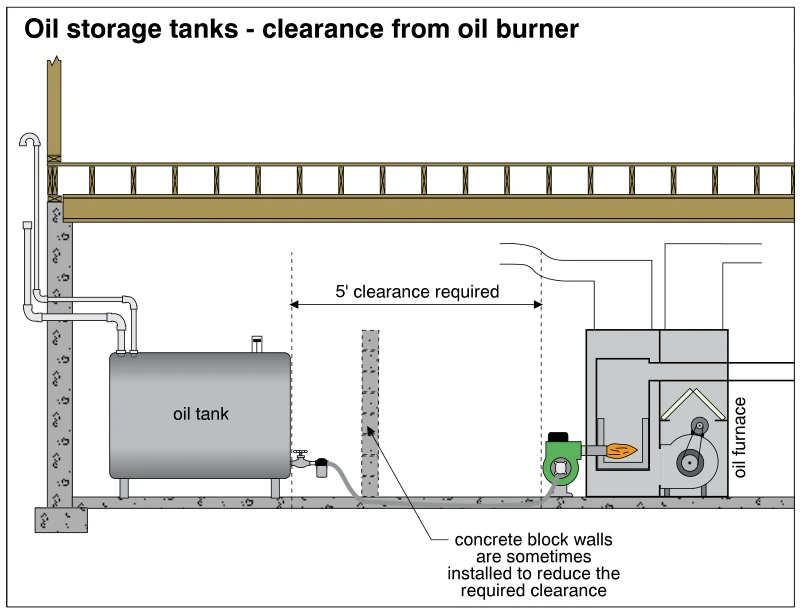
0822Oil storage tanks - clearance from oil burner
· p. 137
The illustration shows a basement oil storage tank beside an oil-fired furnace, with a dimension indicating 5 feet of required clearance between the tank and the burner. A fuel line runs from the tank outlet along the floor to the furnace burner. Tank piping passes through the exterior foundation wall, and the tank stands on short legs above the slab. A short concrete block wall is shown between the tank and burner, with an annotation explaining that such walls are sometimes installed to reduce the required clearance. The furnace is drawn in cutaway to show the burner flame and internal components.
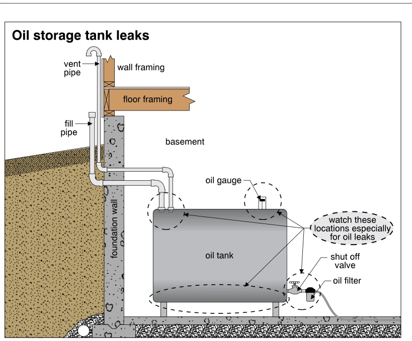 0823
0823Oil storage tank leaks
· p. 138
The illustration shows a basement fuel oil storage tank beside a foundation wall, with fill and vent pipes passing through the wall to the exterior. An oil gauge is mounted on top of the tank, and a shutoff valve and oil filter connect to the lower side outlet. Dashed outlines and arrows identify the top pipe connections, gauge connection, tank bottom, and outlet valve/filter assembly as locations to check especially for oil leaks. No actual escaping oil is depicted; the drawing identifies potential leak locations.
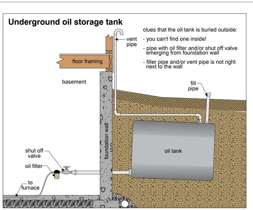 0824
0824Underground oil storage tank
· p. 138
A cutaway shows an oil storage tank buried outside a basement foundation wall. A fill pipe rises from the tank to just above grade, while a separate vent pipe runs underground toward the house and rises beside the exterior wall to a downturned termination. An oil supply line passes through the foundation wall to a shutoff valve and oil filter in the basement, then continues toward the furnace. Notes identify clues to a buried tank, including the absence of an indoor tank, an oil line emerging through the foundation, and fill or vent pipes located away from the wall. No specific defect is depicted.
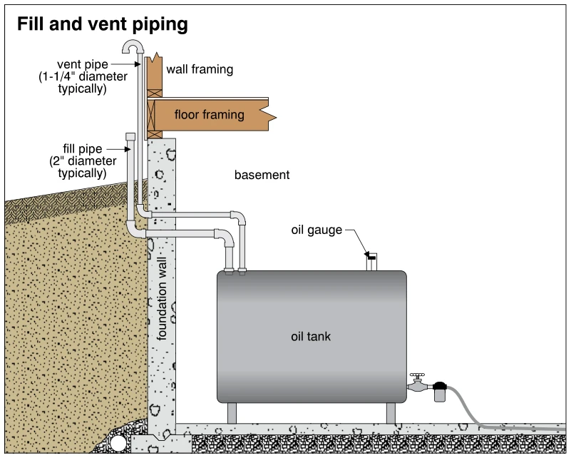 0825
0825Fill and vent piping
· p. 138
A sectional view shows a basement fuel oil storage tank supported on legs beside a foundation wall. Separate fill and vent pipes connect to the top of the tank, pass through the foundation wall, and rise outdoors above grade. The fill pipe has a capped end, while the taller vent pipe terminates in a downward-facing bend. Labels identify typical diameters of 2 inches for the fill pipe and 1-1/4 inches for the vent pipe. An oil gauge is mounted on top of the tank, and a low side outlet connects through a valve and filter assembly to a small fuel line.
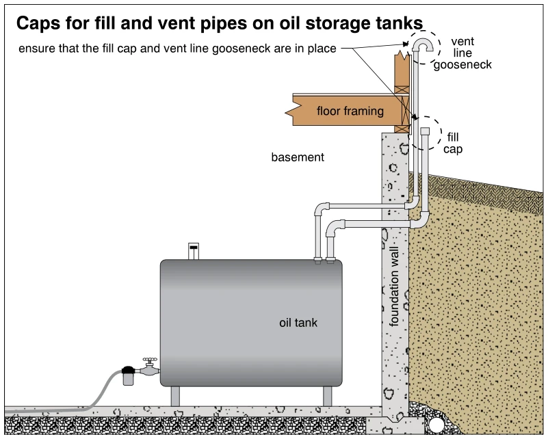 0826
0826Caps for fill and vent pipes on oil storage tanks
· p. 138
The illustration shows a basement oil storage tank with fill and vent pipes passing through the foundation wall and rising outside. The lower exterior pipe has a fill cap, while the taller vent pipe terminates in a downturned gooseneck. Dashed circles and arrows emphasize checking that both protective terminations are in place. The tank stands on legs on the basement floor, with a small fuel outlet assembly and line at its lower side.
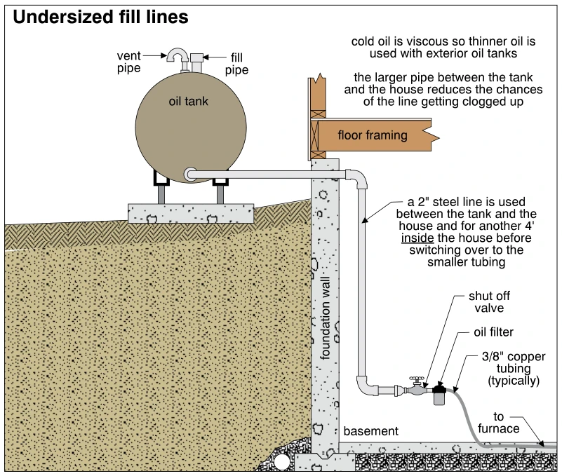 0827
0827Undersized fill lines
· p. 138
The illustration shows an exterior oil storage tank on supports and a concrete pad beside a house foundation, with fill and vent pipes at the top. A large line leaves the lower part of the tank, passes through the foundation wall, and descends into the basement. The annotations specify a 2-inch steel line between the tank and house and for another 4 feet inside before transitioning to smaller tubing. A shutoff valve and oil filter precede the typically 3/8-inch copper tubing leading toward the furnace. Although titled "Undersized fill lines," the drawing explains a larger tank-to-house supply line arrangement intended to reduce clogging and notes that thinner oil is used in exterior tanks because cold oil is viscous.
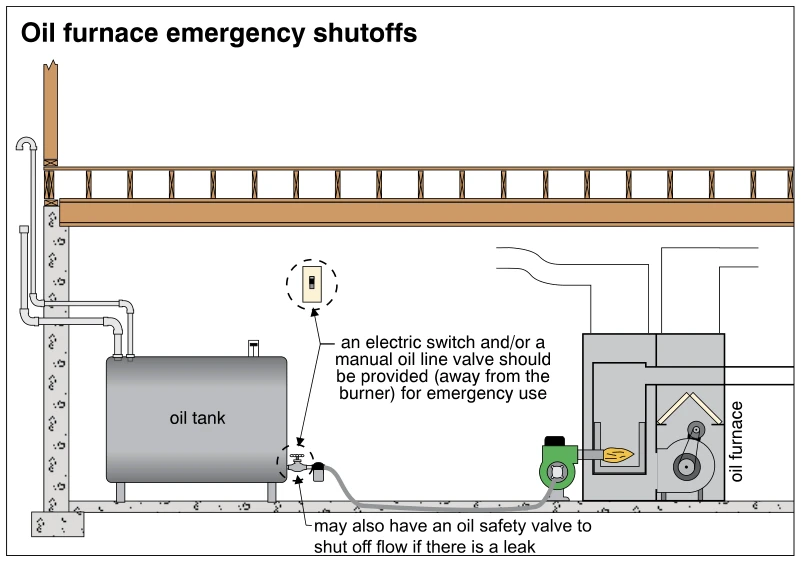 0828
0828Oil furnace emergency shutoffs
· p. 138
The illustration shows an oil storage tank supplying an oil furnace burner through a fuel line near the basement floor. Tank piping passes through the foundation wall to the exterior, and the furnace is shown in cutaway with its burner, combustion area, blower, and duct connections. An electric switch and a manual oil line valve near the tank are highlighted as emergency shutoffs located away from the burner. A separate annotation identifies an optional oil safety valve that shuts off fuel flow if there is a leak.
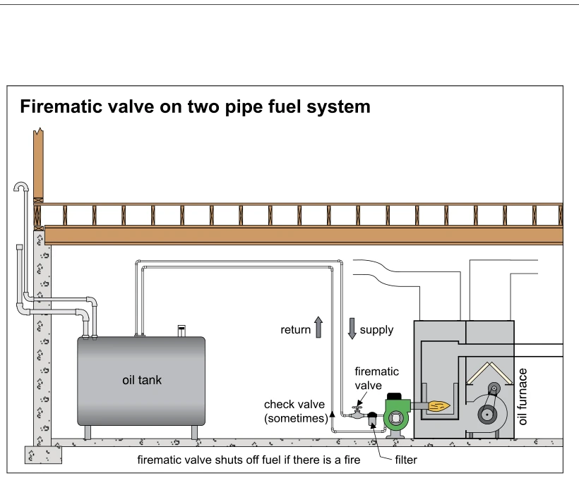 0828.5
Firematic valve on two pipe fuel system
· p. 139
The illustration shows a basement oil tank connected to an oil furnace by separate supply and return fuel lines routed overhead. Arrows indicate fuel flowing toward the burner through the supply line and back toward the tank through the return line. A Firematic valve and filter are shown in the supply piping near the burner, while an optional check valve is identified on the return line. An annotation explains that the Firematic valve shuts off fuel if there is a fire. The drawing also shows the tank's exterior fill and vent piping, foundation wall, and floor framing above.
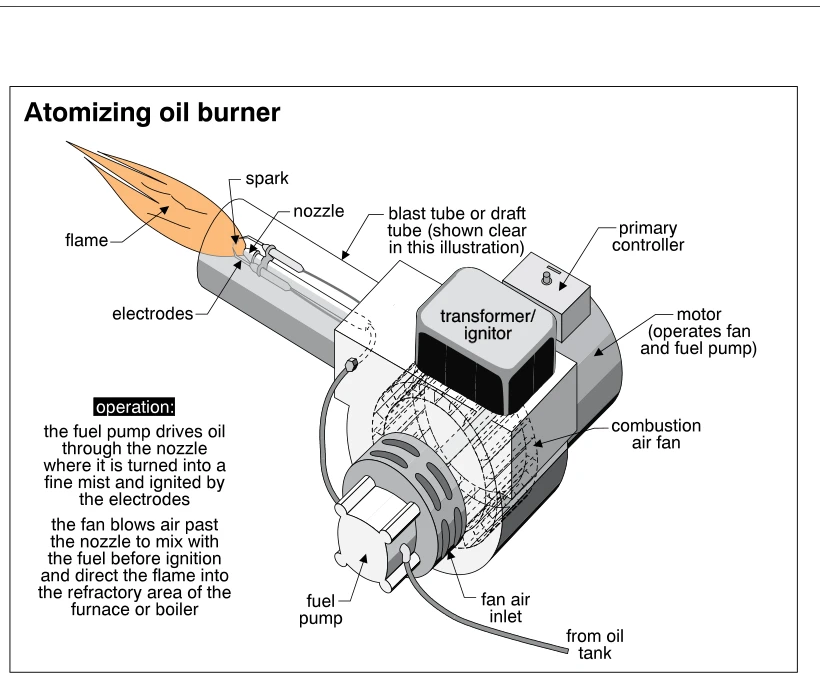 0829
0829Atomizing oil burner
· p. 139
The illustration shows an atomizing oil burner with its blast tube drawn transparent to expose the nozzle and ignition electrodes. A fuel pump receives oil from the oil tank and delivers it to the nozzle, where it is atomized into a fine mist and ignited by an electrode spark. A motor operates both the fuel pump and combustion air fan, which draws air through the fan air inlet and blows it past the nozzle to mix with the fuel. The transformer/ignitor and primary controller are mounted above the burner housing. A flame extends from the end of the blast tube; no defects are depicted.
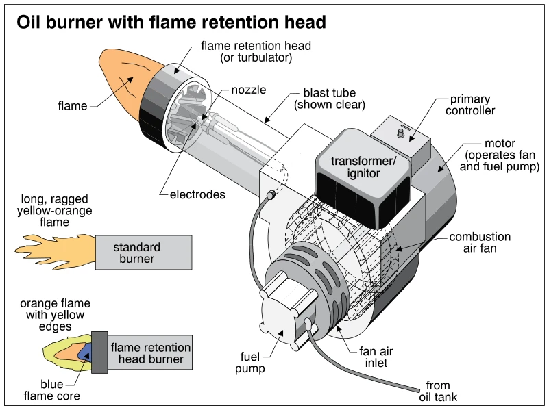 0830
0830Oil burner with flame retention head
· p. 139
The illustration shows an oil burner with a flame retention head, also called a turbulator, at the outlet of a transparent blast tube. The cutaway view identifies the nozzle and ignition electrodes inside the tube, with the flame extending beyond the retention head. The burner assembly includes a transformer/ignitor, primary controller, motor, combustion air fan, fan air inlet, and fuel pump connected to a line from the oil tank. Two inset diagrams compare the long, ragged yellow-orange flame of a standard burner with the shorter orange flame, yellow edges, and blue core of a flame retention head burner. No installation defect is explicitly depicted.
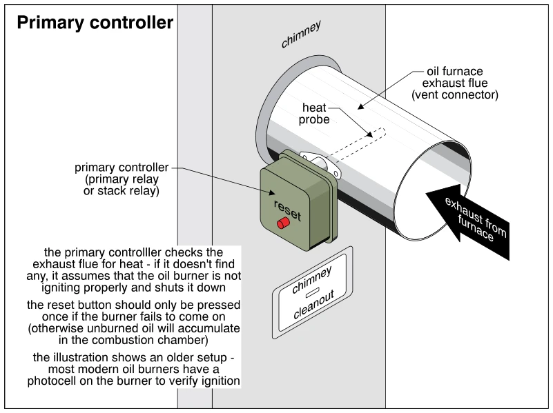 0831
0831Primary controller
· p. 139
The illustration shows an older oil-furnace primary controller, also called a primary relay or stack relay, mounted on the exhaust vent connector at a chimney. A heat probe extends into the connector, and an arrow indicates exhaust flow from the furnace toward the chimney. The controller has a reset button, and a chimney cleanout is shown below the connector. Annotations explain that the controller shuts the burner down if it does not detect exhaust heat, and warn that repeated resets can accumulate unburned oil in the combustion chamber. A note contrasts this older arrangement with modern oil burners that use a photocell to verify ignition.
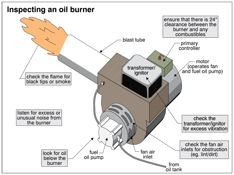 0832
0832Inspecting an oil burner
· p. 139
The illustration shows an oil burner with a flame emerging from its blast tube and identifies the primary controller, transformer/ignitor, motor, fuel oil pump, and fan air inlet. The motor operates both the fan and the fuel oil pump, which is connected to a line from the oil tank. Inspection annotations direct the reader to check for black flame tips or smoke, excess or unusual noise, transformer/ignitor vibration, oil beneath the burner, and obstructed fan air inlets. A separate note specifies 24 inches of clearance between the burner and combustibles. These are inspection checkpoints rather than confirmed defects in the pictured burner.
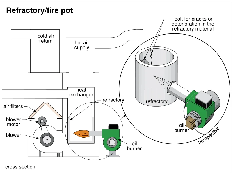 0833
0833Refractory/fire pot
· p. 139
The illustration shows a cross section of an oil furnace alongside an enlarged perspective of its refractory fire pot and oil burner. The furnace includes a cold-air return, air filters, a belt-driven blower, a heat exchanger, and a hot-air supply. The burner projects a flame into the refractory-lined combustion chamber. The enlarged view shows a cylindrical refractory chamber with the burner entering through its side. Arrows identify cracking and localized deterioration in the refractory material as conditions to inspect.
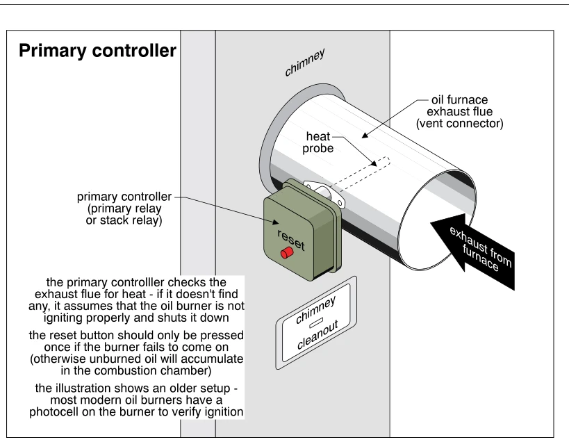 0834
0834Primary controller
· p. 140
The illustration shows an older oil-furnace primary controller mounted on the exhaust vent connector where it enters a chimney. A heat probe projects into the connector to detect heat from furnace exhaust, and the controller has a reset button. The annotations explain that the controller shuts down the burner if exhaust heat is not detected, indicating failed ignition. They warn against pressing the reset button more than once because unburned oil may accumulate in the combustion chamber. A chimney cleanout is shown below the connector, and a note contrasts this older arrangement with modern photocell ignition verification.
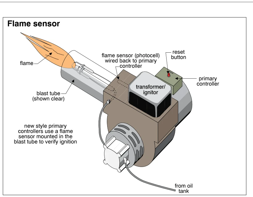 0835
0835Flame sensor
· p. 140
The illustration shows an oil burner assembly with its blast tube rendered transparent to reveal the internal burner components and flame sensor. A flame extends from the end of the blast tube. The photocell flame sensor is mounted in the blast tube and wired back to the primary controller to verify ignition. The primary controller has a reset button and sits beside the transformer/ignitor above the burner housing. A fuel supply line is identified as coming from the oil tank.
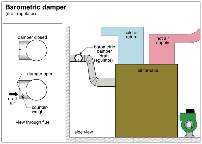 0836
0836Barometric damper
· p. 140
The illustration shows an oil furnace with cold-air return and hot-air supply ducts and a flue connector extending toward a wall. A barometric damper, identified as a draft regulator, is mounted in the flue connector near the wall. An inset viewed through the flue compares the damper in closed and open positions. The open view shows draft air entering past the pivoting damper plate and identifies its counterweight. No defect or improper installation is indicated.
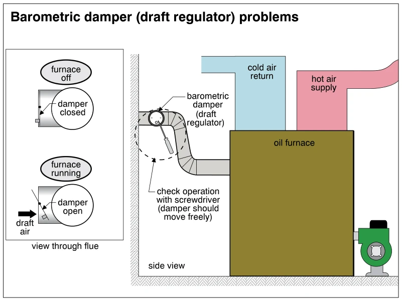 0837
0837Barometric damper (draft regulator) problems
· p. 140
The illustration shows an oil furnace with cold-air return and hot-air supply ducts and a flue connector leading toward a wall. A barometric damper, also called a draft regulator, is installed in the flue connector. A screwdriver is shown checking the damper, with an annotation stating that it should move freely. Inset views through the flue show the damper closed with the furnace off and open to admit draft air with the furnace running. Although the title refers to problems, the drawing illustrates expected operation and an operational check rather than a specific visible failure.
 0838
0838Spillage from barometric damper
· p. 140
The illustration shows an oil furnace with cold-air return and hot-air supply ducts and a flue connector extending toward a wall. A barometric damper, identified as a draft regulator, is installed in the flue connector near the wall. A dashed circle and callout identify the damper as a location to check for exhaust-gas spillage. An enlarged view through the flue shows the damper stuck open, with an arrow indicating exhaust gases leaking into the house.
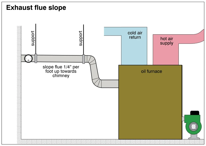 0839
0839Exhaust flue slope
· p. 140
The illustration shows an oil furnace connected to a chimney by a metal exhaust flue connector. Elbows raise the connector from the furnace outlet to a nearly horizontal run entering the chimney at the left. The annotation specifies a rise of 1/4 inch per foot toward the chimney, and two overhead supports secure the connector. A circular draft-control fitting is shown near the chimney connection. Cold-air return and hot-air supply ducts connect to the top of the furnace, and an oil burner is mounted low on its right side.
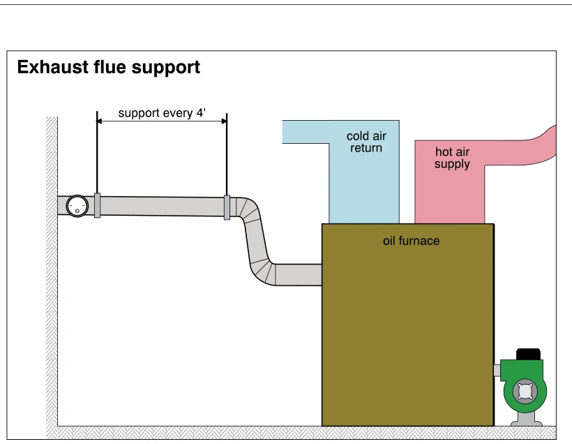 0840
0840Exhaust flue support
· p. 141
The illustration shows an oil furnace with cold-air return and hot-air supply ducts above it and an oil burner mounted at its lower right side. A metal exhaust flue connector exits the left side of the furnace, rises through two elbows, and runs toward a wall connection. Two suspended supports secure the upper flue run, with an annotation specifying support every 4 feet. A circular draft-control device is shown in the flue near the wall connection.
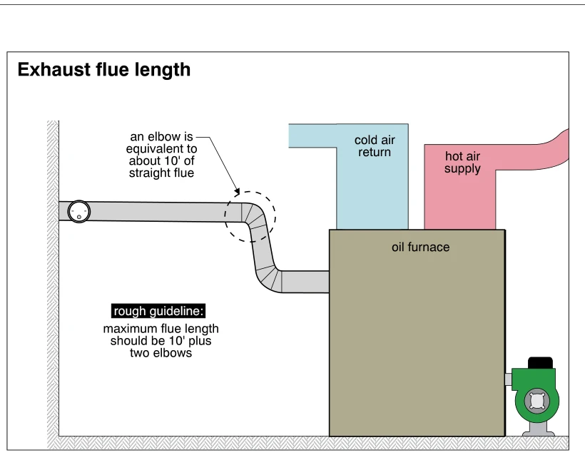 0841
0841Exhaust flue length
· p. 141
The illustration shows an oil furnace with a cold air return, hot air supply, and an exhaust flue extending to a wall opening. The flue connector rises through two elbows before continuing horizontally toward the wall, with a round fitting shown near the wall end. A dashed circle highlights one elbow, and a callout states that an elbow is equivalent to about 10 feet of straight flue. A separate annotation gives a rough guideline that maximum flue length should be 10 feet plus two elbows; no specific defect is marked.
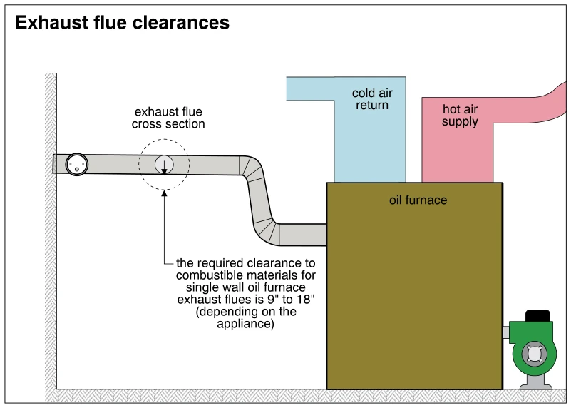 0842
0842Exhaust flue clearances
· p. 141
The illustration shows an oil furnace with a cold-air return duct, hot-air supply duct, and an exhaust flue extending toward a wall. The single-wall flue rises through elbows from the furnace and continues horizontally to the wall connection. A cross-section inset and dashed circle indicate the clearance zone around the flue. The annotation specifies a required clearance to combustible materials of 9 to 18 inches, depending on the appliance.
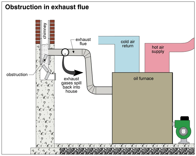 0843
0843Obstruction in exhaust flue
· p. 141
The illustration shows an oil-fired forced-air furnace connected to a masonry chimney by an exhaust flue pipe with elbows. Cold-air return and hot-air supply ducts connect to the top of the furnace, and an oil burner is mounted at its lower side. An obstruction is depicted inside the chimney near the flue connection. A large curved arrow shows exhaust gases spilling back into the house through the round opening in the flue pipe rather than venting up the chimney.
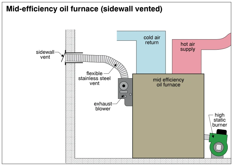 0844
0844Mid-efficiency oil furnace (sidewall vented)
· p. 141
The illustration shows a mid-efficiency oil furnace with a high static burner mounted on its lower right side. Cold-air return and hot-air supply ducts connect to the top of the furnace. An exhaust blower on the left side connects to a flexible stainless steel vent that curves upward and passes horizontally through an exterior wall. The vent terminates at a sidewall outlet rather than a chimney. No defects or improper practices are indicated.
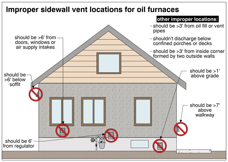 0845
0845Improper sidewall vent locations for oil furnaces
· p. 141
The illustration shows a house elevation with prohibited oil-furnace sidewall vent locations marked by red crossed circles. The marked locations are beneath a soffit, below a window, near a regulator, close to grade, and above a walkway with insufficient clearance. Leader lines give the required separations from these features, including doors, windows, and air supply intakes. Additional notes address separation from oil fill or vent pipes and inside wall corners, and prohibit discharge below confined porches or decks.
Hot Water Boilers (Hydronic Heating) ·Introductionp. 142
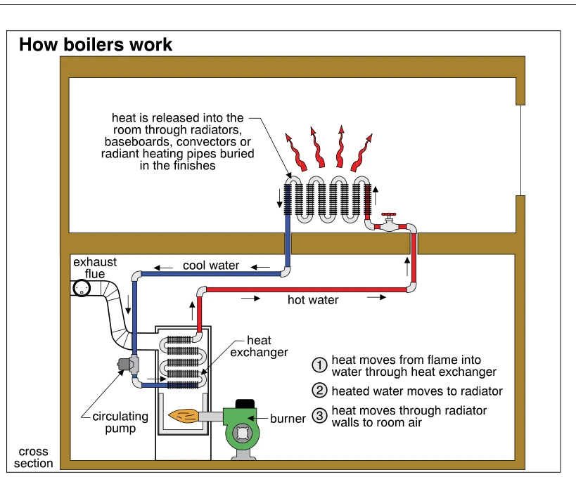 0846
0846How boilers work
· p. 142
A building cross section shows a boiler on the lower level connected to a radiator on the upper level by supply and return piping. A burner heats water through the boiler's heat exchanger, and an exhaust flue carries combustion gases away. Red piping and directional arrows show hot water flowing to the radiator; blue piping shows cooler water returning through a circulating pump to the boiler. Rising red arrows above the radiator depict heat released into the room. The drawing explains normal hot-water heating operation without depicting defects.
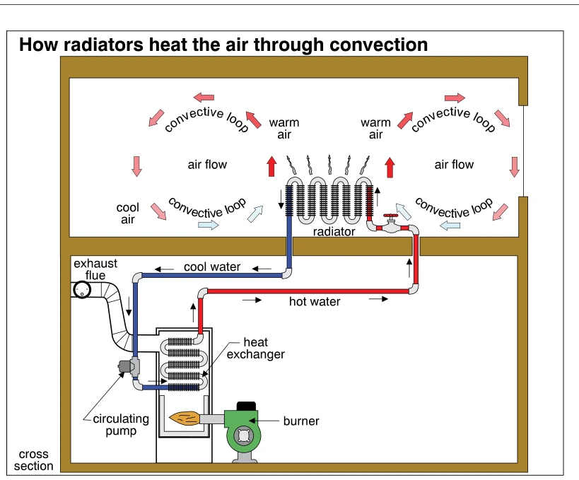 0847
0847How radiators heat the air through convection
· p. 142
A building cross section shows a hot-water heating system with a burner and heat exchanger on the lower level connected to a radiator above. Red supply piping carries hot water to the radiator, while blue return piping carries cooler water back through a circulating pump to the heat exchanger. An exhaust flue carries combustion gases away from the heating appliance. Arrows around the radiator illustrate room-air convection: warmed air rises above the radiator, moves outward, cools and descends, then returns along the floor. The illustration explains normal heat circulation rather than depicting an installation defect.
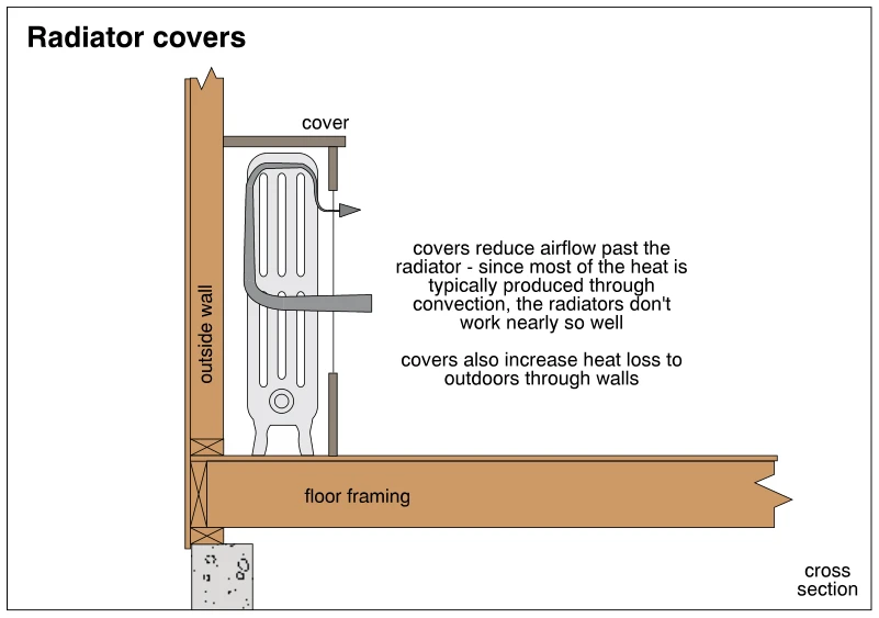 0848
0848Radiator covers
· p. 142
A cross section shows a hot-water radiator standing on a framed floor beside an outside wall, enclosed by a cover. An airflow arrow curves upward along the radiator and exits beneath the cover's top. The annotations explain that covers restrict airflow past the radiator and reduce its convective heating performance. They also note that covers increase heat loss through the outside wall to the outdoors.
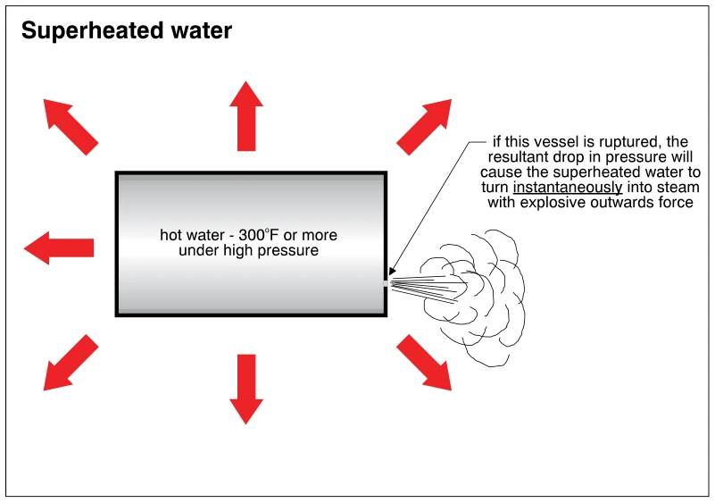 0849
0849Superheated water
· p. 142
A rectangular pressure vessel contains water labeled as 300°F or more under high pressure. A rupture in the right side releases a jet and cloud of steam. The annotation explains that the pressure drop causes the superheated water to turn instantaneously into steam. Large red arrows pointing outward around the vessel illustrate the resulting explosive force.
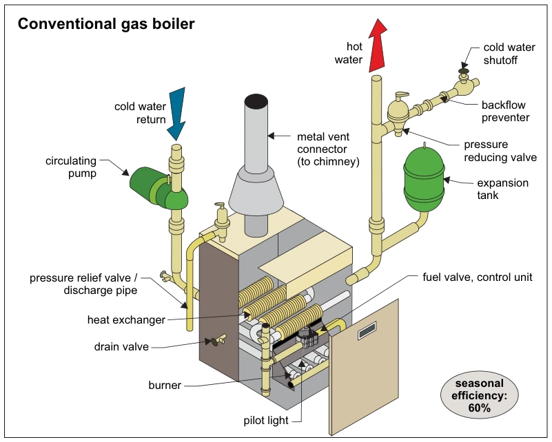 0849.3
Conventional gas boiler
· p. 142
A cutaway illustration shows a conventional gas-fired hydronic boiler with its front access panel removed to expose the heat exchanger, burner, pilot light, and fuel control unit. The cold-water return connects through a circulating pump on the left, while the hot-water supply rises on the right. A cold-water makeup connection includes a shutoff, backflow preventer, and pressure reducing valve, with an expansion tank connected below. A metal vent connector extends upward toward the chimney, and a pressure relief valve with discharge pipe and a drain valve are identified on the boiler. The illustration states a seasonal efficiency of 60% and does not explicitly depict a defect.
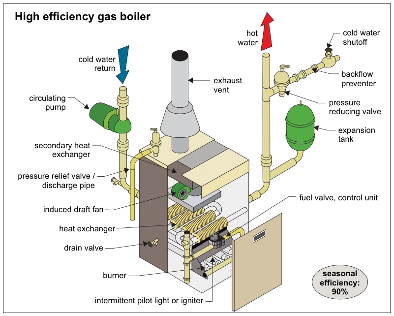 0849.6
High efficiency gas boiler
· p. 142
The illustration shows a high-efficiency gas boiler with its front access panel removed to expose the burner, heat exchanger, ignition equipment, and fuel controls. A circulating pump is installed on the cold-water return piping, while the hot-water supply piping connects to an expansion tank and a makeup-water connection with a shutoff, backflow preventer, and pressure reducing valve. A secondary heat exchanger and induced draft fan are identified near the top of the boiler beneath the exhaust vent. The drawing also identifies a pressure relief valve with discharge piping and a drain valve. A note states a seasonal efficiency of 90%; no defect is explicitly depicted.
Hot Water Boilers (Hydronic Heating) ·Heat Exchangersp. 143
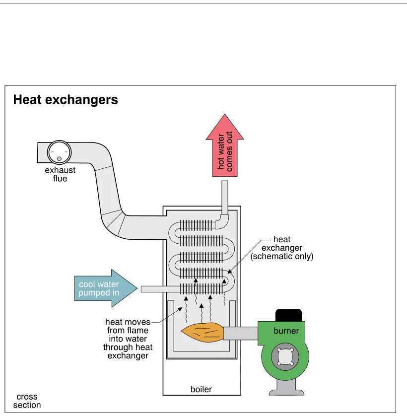 0850
0850Heat exchangers
· p. 143
The illustration shows a schematic cross section of a hot-water boiler with a side-mounted burner firing into the lower combustion chamber. Cool water is pumped into the bottom of a serpentine, finned heat exchanger, and hot water exits through a pipe at the top. Upward arrows show heat moving from the flame through the heat exchanger into the water. An exhaust flue connects to the upper portion of the boiler and carries combustion exhaust away. No defects or improper installation practices are depicted.
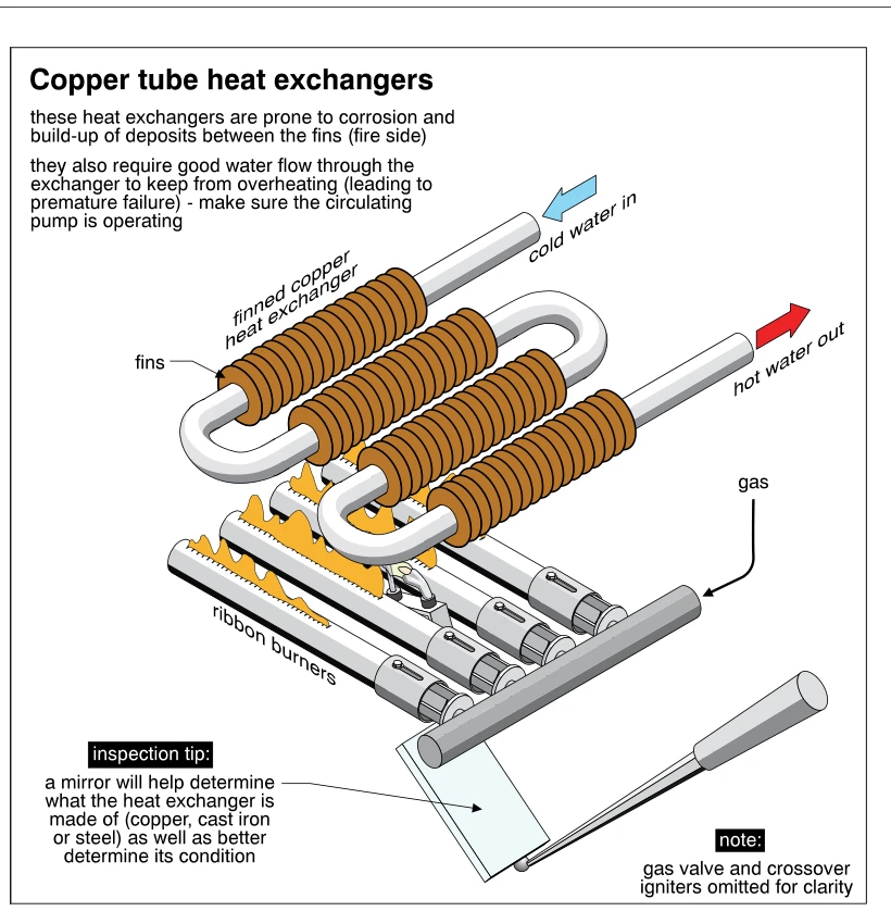 0851
0851Copper tube heat exchangers
· p. 143
The illustration shows a serpentine finned copper heat exchanger positioned above gas-fired ribbon burners in a boiler. Arrows identify cold water entering one end and hot water leaving the other, while a gas supply feeds the burner manifold below. An inspection mirror is shown beneath the assembly to help identify the exchanger material and assess its condition. Annotations warn of corrosion and deposits between the fire-side fins and emphasize adequate water circulation to prevent overheating and premature failure. The gas valve and crossover igniters are explicitly omitted for clarity.
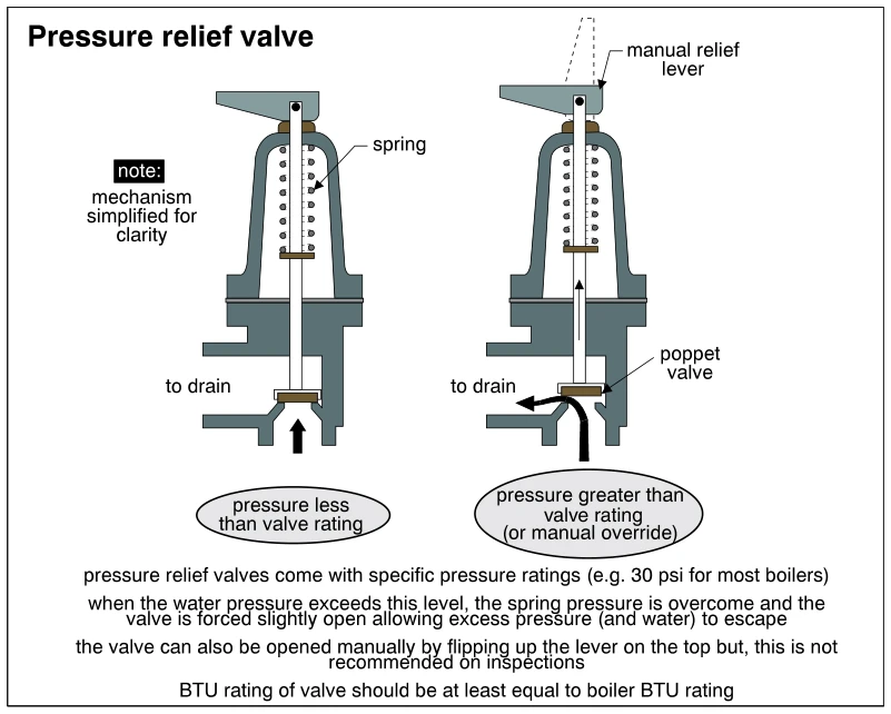 0852
0852Pressure relief valve
· p. 143
Two simplified cross-sections show a boiler pressure relief valve in its closed and open states. On the left, spring force holds the poppet valve seated when water pressure is below the valve rating. On the right, pressure above the rating lifts the poppet, allowing water to discharge through the side outlet to a drain. A top-mounted manual relief lever can also lift the valve stem, with a dashed outline indicating lever movement. Notes identify 30 psi as a typical boiler relief pressure, require valve BTU capacity at least equal to boiler BTU rating, and discourage manual operation during inspections.
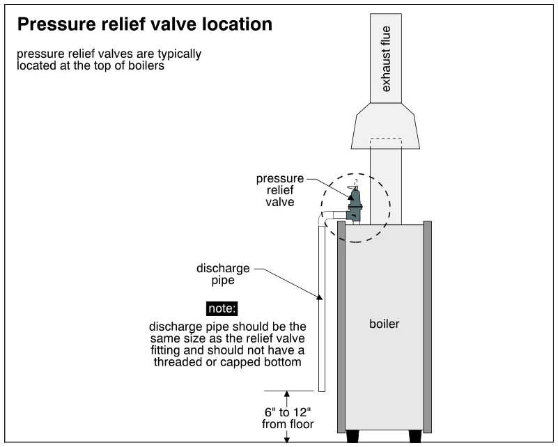 0853
0853Pressure relief valve location
· p. 143
The illustration shows a boiler with a pressure relief valve mounted at its top and an exhaust flue extending upward. A dashed circle highlights the relief valve location. A discharge pipe connects to the valve and runs down beside the boiler, terminating 6 to 12 inches above the floor. The note specifies that the discharge pipe should match the relief valve fitting size and must not have a threaded or capped bottom.
Hot Water Boilers (Hydronic Heating) ·Controlsp. 144
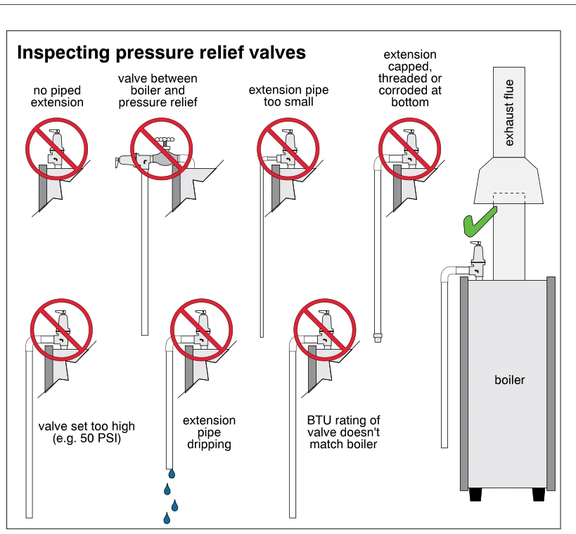 0854
0854Inspecting pressure relief valves
· p. 144
The illustration compares seven improper boiler pressure-relief valve conditions with a correct installation marked by a green check. Red prohibition symbols identify a missing discharge extension, a valve between the boiler and relief valve, an undersized extension, and an extension capped, threaded, or corroded at its lower end. Additional examples identify an excessively high pressure setting, a dripping discharge pipe, and a relief-valve BTU rating that does not match the boiler. The correct example shows a relief valve connected at the top of a boiler with a discharge pipe turning downward and terminating with an open end alongside the boiler; an exhaust flue rises above the unit.
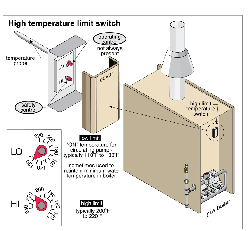 0855
0855High temperature limit switch
· p. 144
The illustration shows a gas boiler with a high-limit temperature switch mounted on its side, along with an enlarged view of the control assembly and its removable cover. A temperature probe projects from the assembly, which contains LO and HI adjustments identified as an operating control and a safety control, respectively. The operating control is noted as not always present. Enlarged dial views identify the low limit as the circulating pump's ON temperature, typically 110°F to 130°F, and note that it is sometimes used to maintain minimum boiler water temperature. The high-limit setting is identified as typically 200°F to 220°F. The boiler is also shown with a vertical flue connection and exposed lower burner and gas-control components.
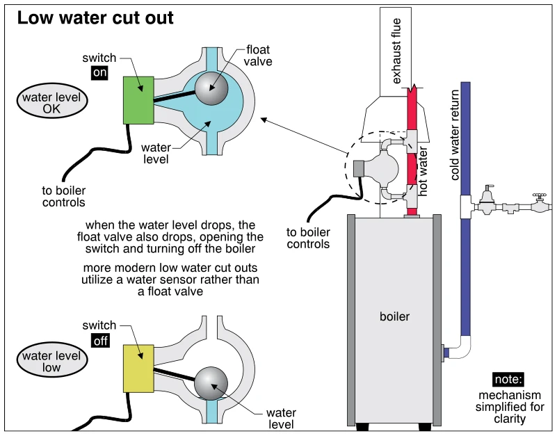 0856
0856Low water cut out
· p. 144
The illustration shows a low-water cut-out connected to the hot-water piping of a boiler, alongside the exhaust flue and cold-water return. Two enlarged sections show a float-operated switch at normal and low water levels. At the normal water level, the raised float holds the switch on; when the water level falls, the float drops, opening the switch and shutting off the boiler. An annotation explains that more modern low-water cut-outs use a water sensor rather than a float valve.
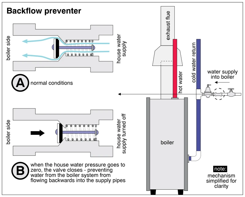 0857
0857Backflow preventer
· p. 144
The illustration shows a backflow preventer in the water supply piping serving a hot-water boiler, with enlarged sectional views of its operation. Under normal conditions, supply water flows past the open spring-loaded valve toward the boiler. When house water pressure drops to zero, the valve closes to prevent boiler water from flowing backward into the house supply piping. The boiler diagram also identifies the hot-water outlet, cold-water return, and exhaust flue. A note states that the mechanism is simplified for clarity.
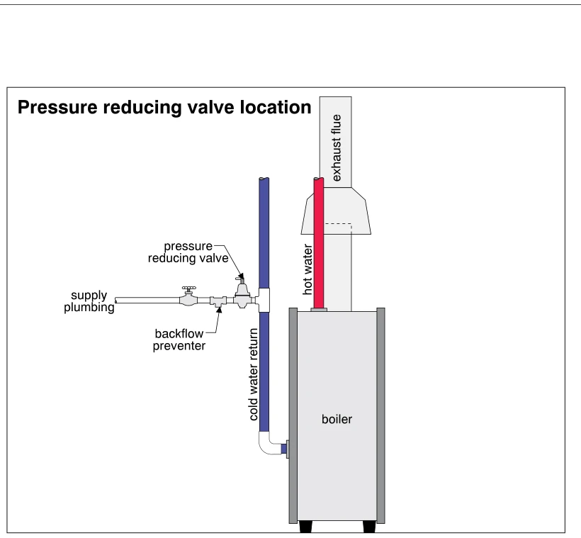 0858
0858Pressure reducing valve location
· p. 145
The illustration shows a heating boiler with a blue cold-water return pipe, a red hot-water supply pipe, and an exhaust flue above it. A horizontal makeup-water supply connects to the cold-water return near the boiler. Along this supply line, a manual shutoff valve precedes a backflow preventer and a pressure reducing valve. The pressure reducing valve is located downstream of the backflow preventer, just before the connection to the return piping.
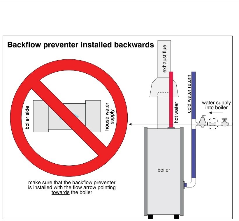 0859
0859Backflow preventer installed backwards
· p. 145
The illustration shows a hot-water boiler with an exhaust flue, hot-water supply piping, cold-water return piping, and a makeup-water supply connection. A dashed circle identifies the backflow preventer on the water supply line, with an enlarged view showing its orientation between the house water supply and the boiler. In the enlarged view, the device's flow arrow points toward the house water supply, and a red prohibition symbol marks this installation as incorrect. The annotation instructs that the backflow preventer's flow arrow must point toward the boiler.
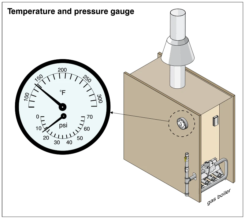 0860
0860Temperature and pressure gauge
· p. 145
The illustration shows a gas boiler with a combination temperature and pressure gauge mounted on its front casing. An enlarged view of the gauge shows separate pointers and scales for water temperature in degrees Fahrenheit and pressure in pounds per square inch. The temperature pointer is near 150°F, and the pressure pointer is between 10 and 20 psi. A vent pipe and draft hood extend above the boiler, while gas piping, a shutoff valve, and burner components are visible near its base. No defect or improper installation is identified.
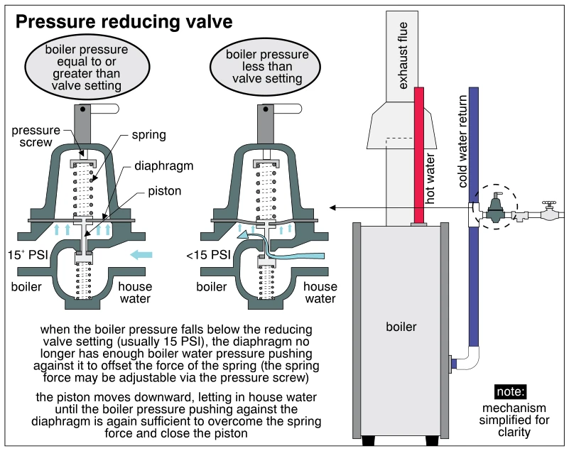 0861
0861Pressure reducing valve
· p. 145
The illustration shows a pressure reducing valve supplying makeup water from the house water system to a hot-water boiler. Two simplified valve cross-sections compare operation when boiler pressure is at or above the valve setting and when it falls below the setting, typically 15 PSI. At sufficient pressure, the diaphragm holds the piston closed against spring force; at low pressure, the spring moves the piston downward to admit house water until pressure is restored. The pressure screw adjusts spring force. A system diagram locates the valve on the water supply connection near the boiler’s cold-water return and also shows the hot-water outlet and exhaust flue.
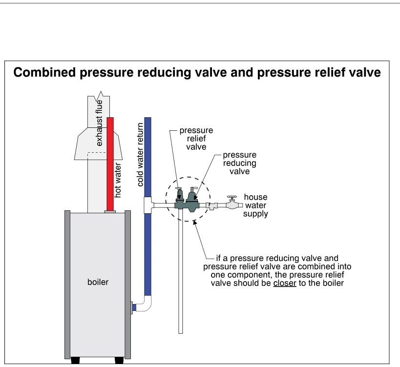 0862
0862Combined pressure reducing valve and pressure relief valve
· p. 146
The illustration shows a hot-water heating boiler with an exhaust flue, a hot-water supply riser, and a cold-water return pipe. The house water supply connects to the boiler return through a combined pressure reducing valve and pressure relief valve assembly. A dashed circle highlights the assembly, with the pressure relief valve positioned on the boiler side of the pressure reducing valve. A discharge pipe extends downward from the relief valve. The annotation specifies that the relief valve should be closer to the boiler when the two valves are combined into one component.
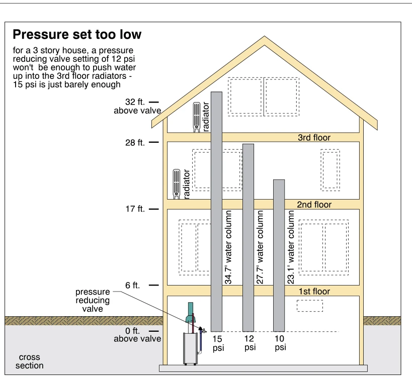 0863
0863Pressure set too low
· p. 146
A cross section of a three-story house shows a basement boiler and pressure reducing valve, with radiators on the second and third floors. Three vertical columns compare the water-column heights supported by pressures of 15, 12, and 10 psi: 34.7, 27.7, and 23.1 feet respectively. The third-floor radiator is indicated at 32 feet above the valve. The annotation explains that a 12 psi valve setting cannot push water to the third-floor radiators and that 15 psi is just barely sufficient.
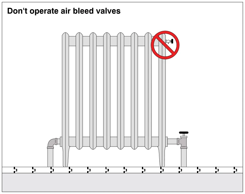 0864
0864Don't operate air bleed valves
· p. 146
The illustration shows a freestanding sectional heating radiator connected to pipes at both lower ends. A hand-operated valve is installed on the lower-right pipe connection. A small air bleed valve near the radiator's upper-right corner is overlaid with a red prohibition symbol. The figure warns against operating radiator air bleed valves during inspection; no physical defect is depicted.
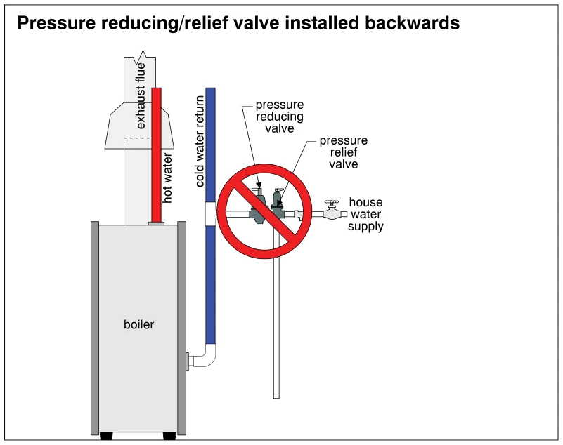 0865
0865Pressure reducing/relief valve installed backwards
· p. 146
The illustration shows a hot-water heating boiler with an exhaust flue, a red hot-water supply pipe, and a blue cold-water return pipe. A horizontal house water supply connects to the boiler return through a pressure reducing/relief valve assembly. The pressure reducing valve is depicted on the boiler side of the assembly, while the pressure relief valve is on the house water supply side with a discharge pipe extending downward. A red prohibition symbol over the assembly identifies this reversed installation as incorrect.
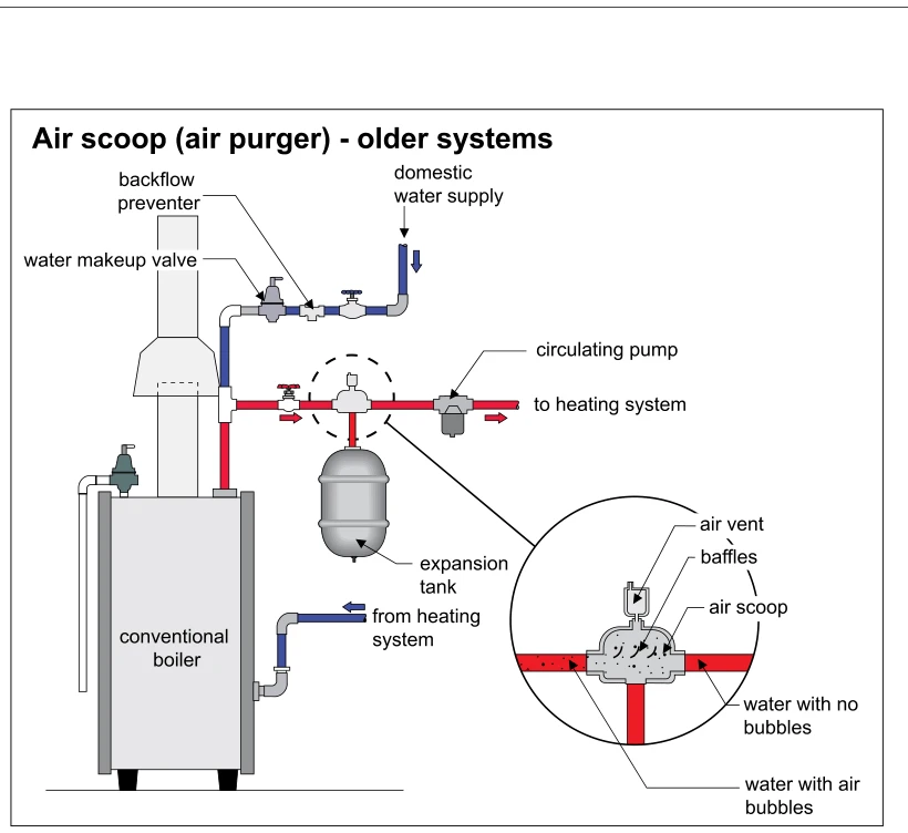 0865.3
Air scoop (air purger) - older systems
· p. 147
The diagram shows a conventional boiler connected to a hydronic heating system, with red supply piping and blue return and makeup-water piping. An air scoop is installed in the supply line upstream of the circulating pump, with an air vent above it and an expansion tank connected below. An enlarged cutaway shows baffles separating air bubbles from the flowing water so air can escape through the vent, while water without bubbles continues toward the heating system. The domestic water supply connects through a backflow preventer and water makeup valve to the boiler piping. Arrows indicate the direction of water flow.
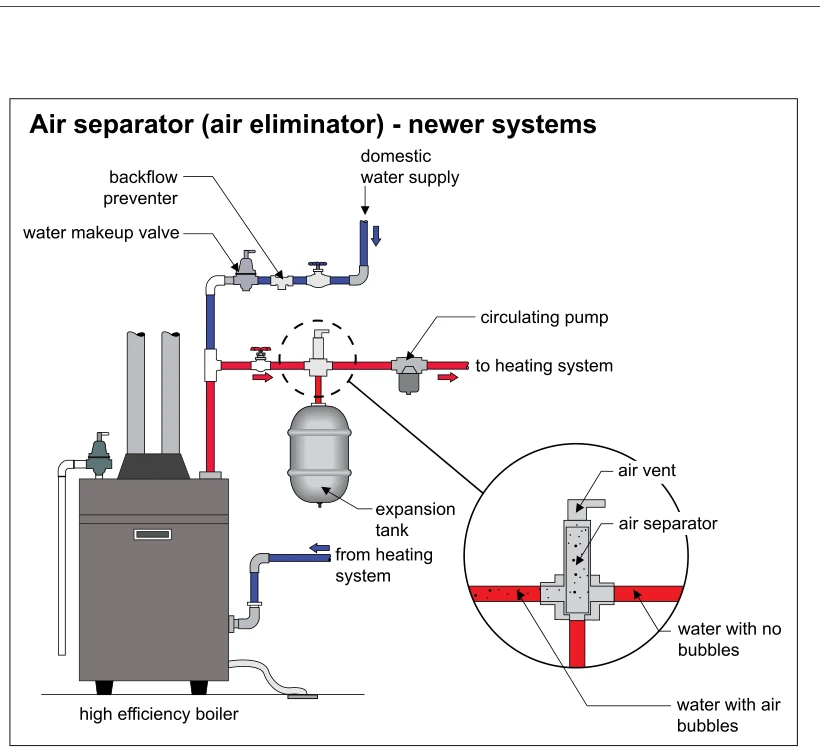 0865.4
Air separator (air eliminator) - newer systems
· p. 147
The illustration shows a high efficiency boiler connected to a hydronic heating system, with red supply piping and blue return piping indicating flow direction. An air separator is installed in the supply line upstream of the circulating pump, with an expansion tank connected below it. A domestic water supply connection includes a backflow preventer and water makeup valve. An enlarged cutaway shows water containing air bubbles entering the separator, air collecting toward the top-mounted air vent, and water with no bubbles leaving toward the heating system.
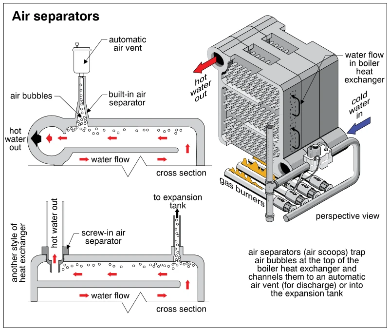 0866
0866Air Separators on Boiler
· p. 147
The illustration shows two cross sections of boiler heat exchangers with air separators, alongside a perspective cutaway of a gas-fired boiler heat exchanger and burners. In the upper cross section, air bubbles collect at a built-in separator and rise to an automatic air vent while hot water exits to the left. The lower cross section shows a screw-in air separator at the hot-water outlet and a separate upward connection labeled to the expansion tank. Arrows indicate water circulation through the heat exchangers, with cold water entering and hot water leaving the perspective assembly. The figure explains air removal arrangements without depicting a defect.
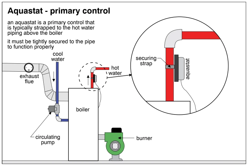 0867
0867Aquastat - primary control
· p. 147
The illustration shows a hot-water heating boiler with a burner, exhaust flue, circulating pump, cool-water return piping, and hot-water supply piping. An aquastat is strapped to the hot-water pipe above the boiler. An enlarged detail shows the aquastat against the vertical pipe, held by a securing strap, with a wire extending downward. The annotation identifies the aquastat as a primary control and states that it must be tightly secured to the pipe to function properly.
Hot Water Boilers (Hydronic Heating) ·Distribution Systemsp. 148
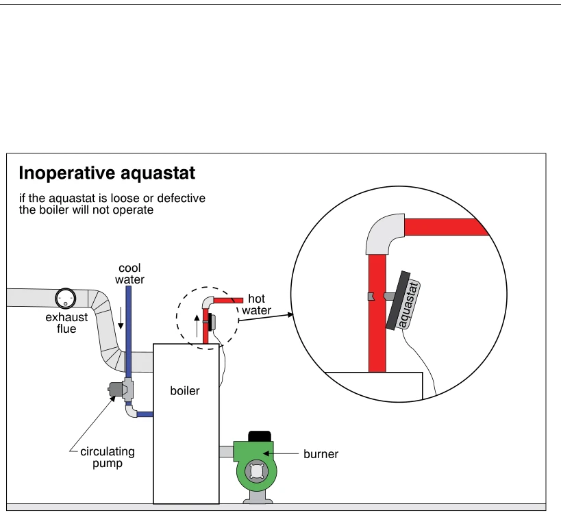 0868
0868Inoperative aquastat
· p. 148
The illustration shows a hot-water heating boiler with a burner, exhaust flue, circulating pump, cool-water return, and hot-water supply piping. An aquastat is mounted on the hot-water pipe leaving the boiler. A circular enlarged detail shows the aquastat tilted away from the pipe, illustrating a loose mounting condition. The annotation states that the boiler will not operate if the aquastat is loose or defective.
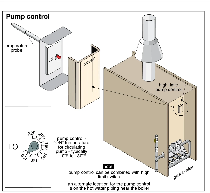 0869
0869Pump control
· p. 148
The illustration shows a gas boiler with a high-limit/pump control mounted on its jacket. An enlarged exploded view shows the control enclosure, removable cover, temperature probe, and adjustment marked “LO.” A separate detail illustrates the temperature adjustment dial, with an annotation identifying the typical circulating-pump turn-on temperature as 110°F to 130°F. Notes explain that the pump control can be combined with the high-limit switch or located on hot-water piping near the boiler. The boiler is also shown with a vent connection, draft hood, and exposed lower gas piping and burner components.
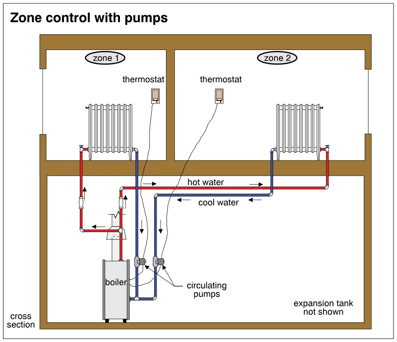 0870
0870Zone control with pumps
· p. 148
A building cross section shows a boiler supplying two hydronic heating zones, each with a radiator and thermostat. Red piping carries hot water from the boiler to the radiators, while blue piping returns cooler water to the boiler. Each zone has a separate circulating pump on its return piping, with control lines drawn from the corresponding thermostat. Arrows indicate water flow through the supply and return circuits. An annotation states that the expansion tank is not shown.
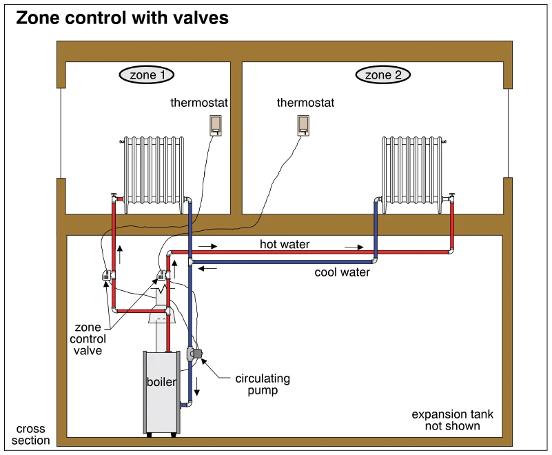 0871
0871Zone control with valves
· p. 148
A building cross section shows a boiler supplying two hydronic heating zones, each with a radiator and thermostat. Red piping carries hot water through separate zone control valves to the radiators, while blue piping returns cooler water to the boiler. Thermostat wiring connects each room control to its associated zone valve. A single circulating pump is shown on the common return near the boiler, and arrows indicate water flow direction. An annotation states that the expansion tank is not shown.
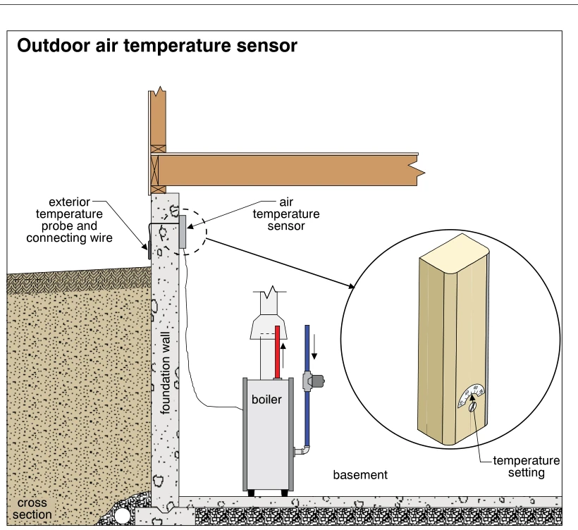 0872
0872Outdoor air temperature sensor
· p. 149
A building cross section shows a basement boiler connected by wiring to an air temperature sensor mounted on the interior face of the foundation wall. An exterior temperature probe is mounted on the outside of the wall near grade and connected to the sensor. An enlarged detail shows the sensor housing and its temperature-setting dial. Red and blue boiler piping includes arrows indicating upward flow on the red pipe and downward flow on the blue pipe. The illustration identifies the outdoor-temperature sensing arrangement without depicting a defect.
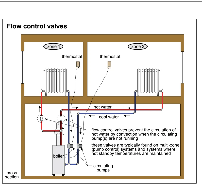 0873
0873Flow control valves
· p. 149
A building cross section shows a two-zone hot-water heating system with a basement boiler and a radiator and thermostat in each zone. Red supply piping carries hot water to the radiators, and blue return piping carries cooler water back through separate circulating pumps. Flow control valves are shown on the supply branches, with arrows indicating the direction of circulation. The annotations explain that these valves prevent convection-driven hot-water circulation when the pumps are off and are typically used in multi-zone pump-controlled systems and systems maintaining hot standby temperatures.
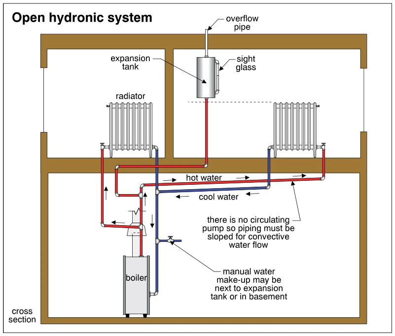 0874
0874Open hydronic system
· p. 149
A building cross section shows an open hydronic heating system with a boiler in the basement and two radiators above. Red supply piping and blue return piping, with directional arrows, illustrate hot water flowing to the radiators and cooler water returning to the boiler. An elevated expansion tank connects to the system and has a sight glass and an overflow pipe extending above the roof. The drawing notes that no circulating pump is used, so the piping must slope to allow convective water flow. A manual water make-up connection is shown in the basement, with a note that it may alternatively be located next to the expansion tank.
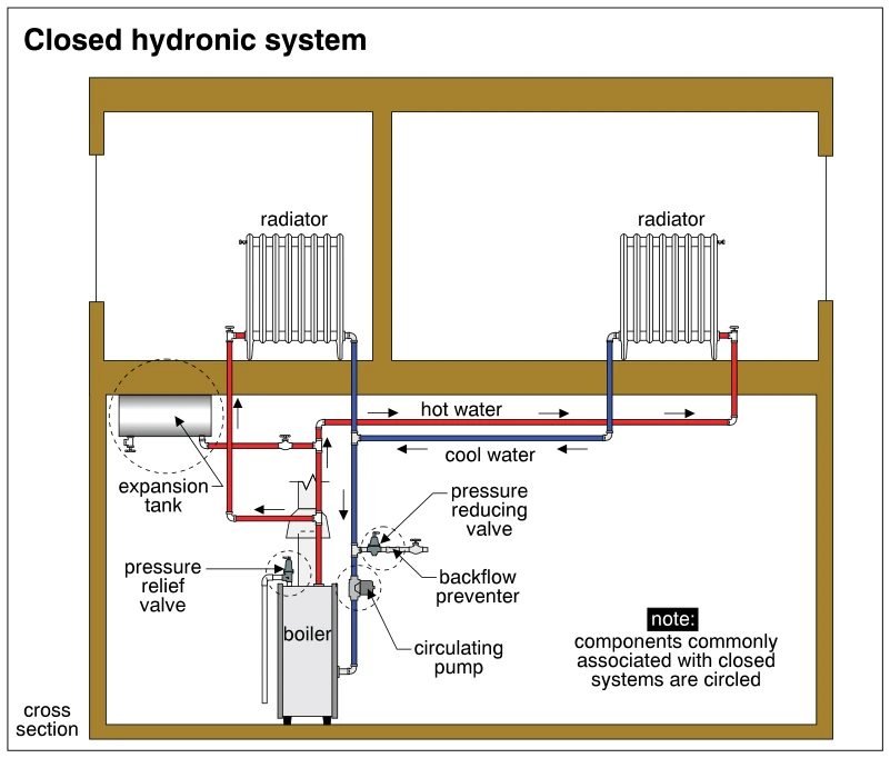 0875
0875Closed hydronic system
· p. 149
A building cross section shows a closed hot-water heating system with a boiler on the lower level and two radiators above. Red supply piping carries hot water to the radiators, while blue return piping carries cooler water back toward the boiler; arrows indicate circulation direction. An expansion tank connects to the heating piping, and a circulating pump is shown on the return near the boiler. A pressure relief valve is located at the boiler, while a pressure reducing valve and backflow preventer are shown on the water-feed connection. Dashed circles highlight components commonly associated with closed systems.
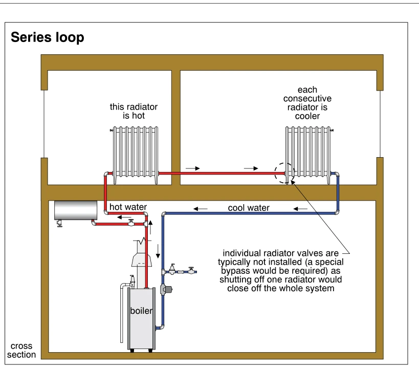 0876
0876Series loop
· p. 150
A building cross section shows a boiler connected to two radiators in a single series-loop hot-water heating circuit. Red piping carries hot water from the boiler through the first radiator and onward to the second, with arrows indicating flow direction. Blue piping returns cooler water from the second radiator to the boiler. The annotations explain that each consecutive radiator is cooler and that individual radiator shutoff valves typically are not installed because closing one would stop flow through the whole system unless a special bypass were provided.
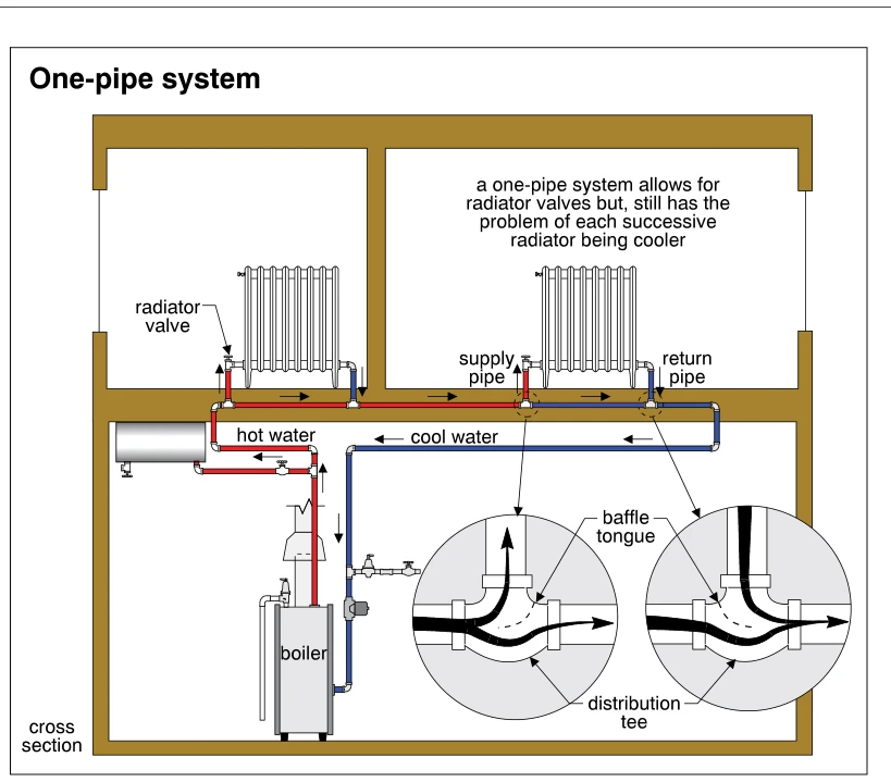 0877
0877One-pipe system
· p. 150
A building cross section shows a boiler connected to two radiators through a one-pipe hot-water heating loop. Arrows indicate heated water moving along the distribution main, with branch supply and return pipes connecting each radiator to that main. Enlarged cross sections of distribution tees show baffle tongues that divert flow into a radiator branch and accommodate returning water. A radiator valve is identified, and the annotation explains that valves are possible in this arrangement but successive radiators receive cooler water. The main loops back to the boiler as a cooler return line.
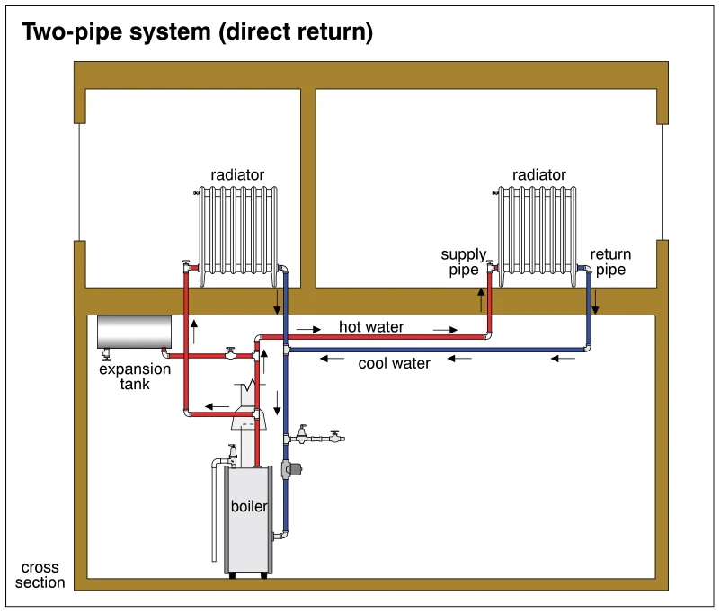 0878
0878Two-pipe system (direct return)
· p. 150
A building cross section shows a two-pipe, direct-return hydronic heating system with a boiler below two radiators. Red supply piping carries hot water from the boiler to each radiator, while blue return piping carries cooler water back to the boiler. Arrows indicate flow direction through the supply and return branches. The nearer radiator has a shorter combined supply-and-return path than the farther radiator. An expansion tank connects to the piping above the boiler.
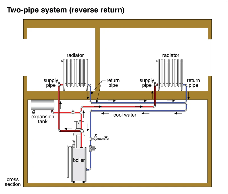 0879
0879Two-pipe system (reverse return)
· p. 150
A building cross section shows a boiler below two radiators connected by a two-pipe reverse-return hydronic heating system. Red supply piping carries heated water from the boiler to each radiator in parallel, while blue return piping collects the cooled water. The return from the radiator nearest the boiler travels toward the farther radiator before looping back to the boiler, illustrating the reverse-return arrangement. Arrows indicate circulation through the supply branches, radiators, and common return piping. An expansion tank is connected to the piping near the boiler.
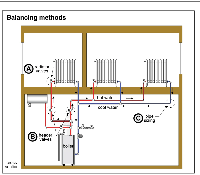 0880
0880Balancing methods
· p. 151
A building cross section shows a hot-water heating system with a boiler below three radiators. Red supply piping carries hot water to the radiators, and blue return piping carries cooled water back to the boiler, with arrows indicating flow direction. Three methods of balancing heat distribution are identified: radiator valves, header valves, and pipe sizing. Dashed circles highlight valve locations and a section of return piping associated with pipe sizing.
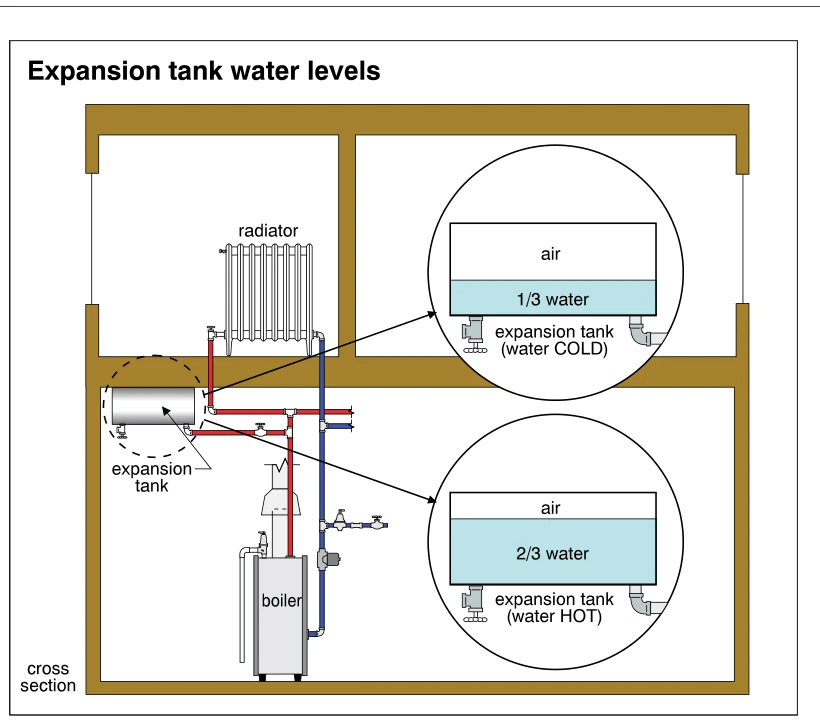 0881
0881Expansion tank water levels
· p. 151
A house cross section shows a boiler connected by red and blue piping to an upstairs radiator, with a horizontal expansion tank near the basement ceiling. Two enlarged tank sections illustrate the water and air volumes under cold and hot operating conditions. With the water cold, water occupies one-third of the tank and air fills the remaining space. With the water hot, water occupies two-thirds of the tank, reducing the air space as the heating water expands. The illustration depicts normal expansion-tank operation rather than a defect.
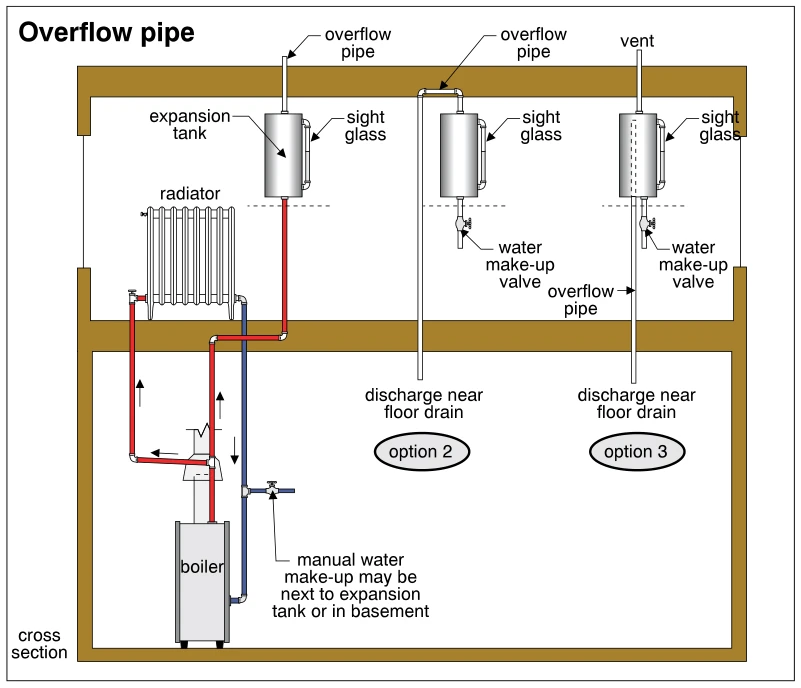 0882
0882Overflow pipe
· p. 151
A building cross section shows a hot-water heating system with a basement boiler, an upper-floor radiator, and an elevated expansion tank with a sight glass. Red supply piping and blue return piping connect the boiler and radiator, with arrows indicating circulation direction. The left-hand expansion tank has an overflow pipe extending above the roof, and a note identifies manual water make-up locations next to the expansion tank or in the basement. Option 2 routes the tank's top overflow connection down to discharge near a floor drain. Option 3 shows a separate top vent and an internal overflow standpipe descending to discharge near a floor drain; both alternatives include a sight glass and a water make-up valve.
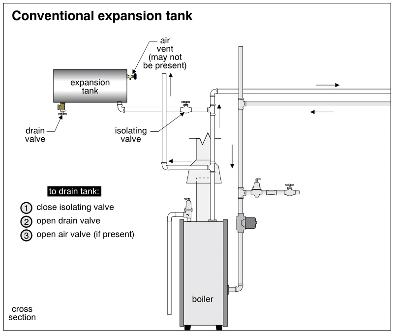 0883
0883Conventional expansion tank
· p. 151
The illustration shows a conventional expansion tank connected to a hot-water heating boiler and its distribution piping. The horizontal tank is positioned above the boiler, with an isolating valve in the connecting pipe, a drain valve beneath the tank, and an optional air vent at its end. Arrows indicate flow directions in the boiler and distribution piping. An annotation gives the tank-draining sequence: close the isolating valve, open the drain valve, and open the air valve if present. The boiler is shown in cross section, with adjacent piping, valves, and a circulator.
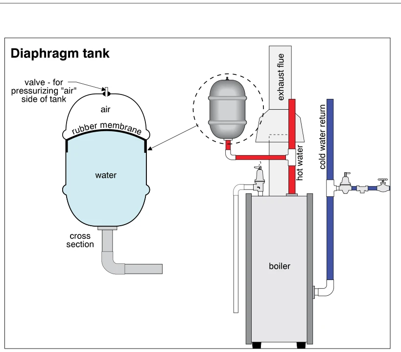 0884
0884Diaphragm tank
· p. 152
The illustration shows a diaphragm expansion tank connected to the hot-water supply piping of a hydronic heating boiler. An enlarged cross section shows a rubber membrane separating the air chamber above from the water chamber below, with a valve at the top for pressurizing the air side. The tank's water-side connection enters at the bottom. The boiler diagram also shows red hot-water supply piping, blue cold-water return piping, an exhaust flue, and associated valves.
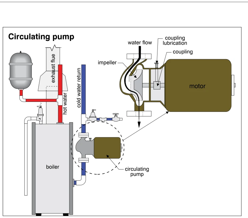 0885
0885Circulating pump
· p. 152
The illustration shows a hot-water heating boiler with a circulating pump installed in the cold-water return piping. Red piping identifies the hot-water supply, while blue piping identifies the return to the boiler; an expansion tank and exhaust flue are also shown. An enlarged cutaway of the pump shows the motor connected through a coupling to the impeller. Arrows trace water entering the top of the pump housing and leaving at the bottom, and a callout identifies the coupling lubrication point. No defect or improper installation is indicated.
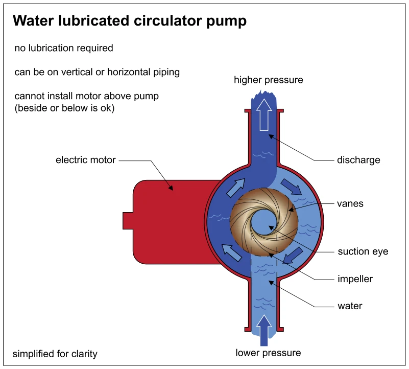 0885.5
Water lubricated circulator pump
· p. 152
A simplified cutaway depicts a water-lubricated circulator pump with an electric motor beside the pump housing on vertical piping. The impeller, curved vanes, and central suction eye are exposed, with arrows indicating water movement from the lower-pressure inlet toward the higher-pressure discharge above. The annotations state that no lubrication is required and that the pump can be installed on vertical or horizontal piping. They also specify that the motor must not be installed above the pump, while a position beside or below it is acceptable.
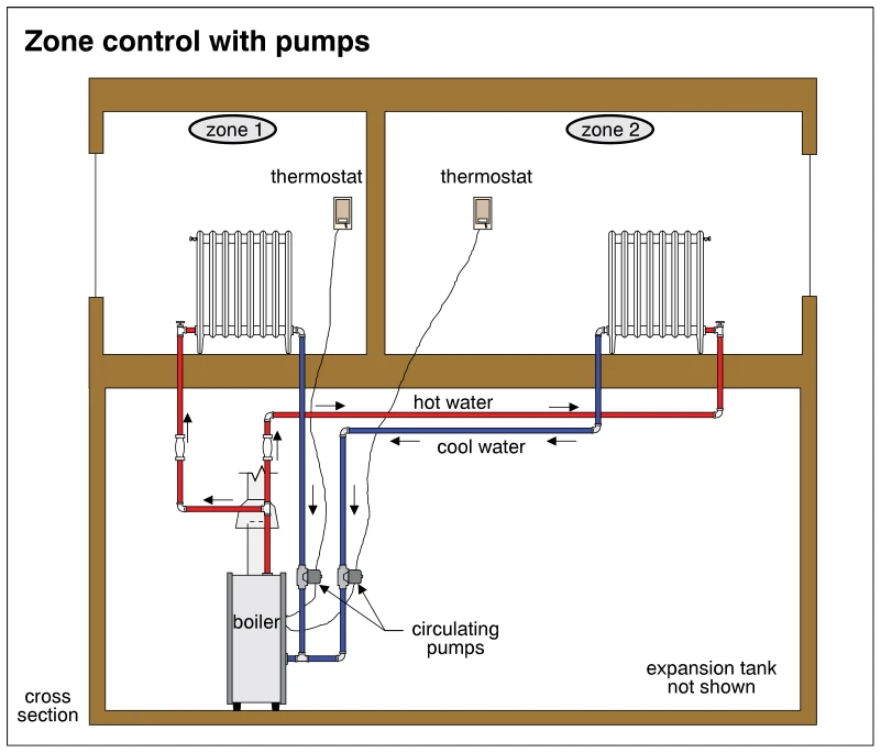 0886
0886Zone control with pumps
· p. 152
A building cross section depicts a two-zone hydronic heating system supplied by a single boiler. Each zone contains a radiator and a thermostat connected by control wiring to a separate circulating pump. Red piping carries hot water from the boiler to the radiators, while blue piping returns cooler water through the pumps to the boiler. Arrows indicate the direction of water circulation in each circuit. An annotation states that the expansion tank is not shown.
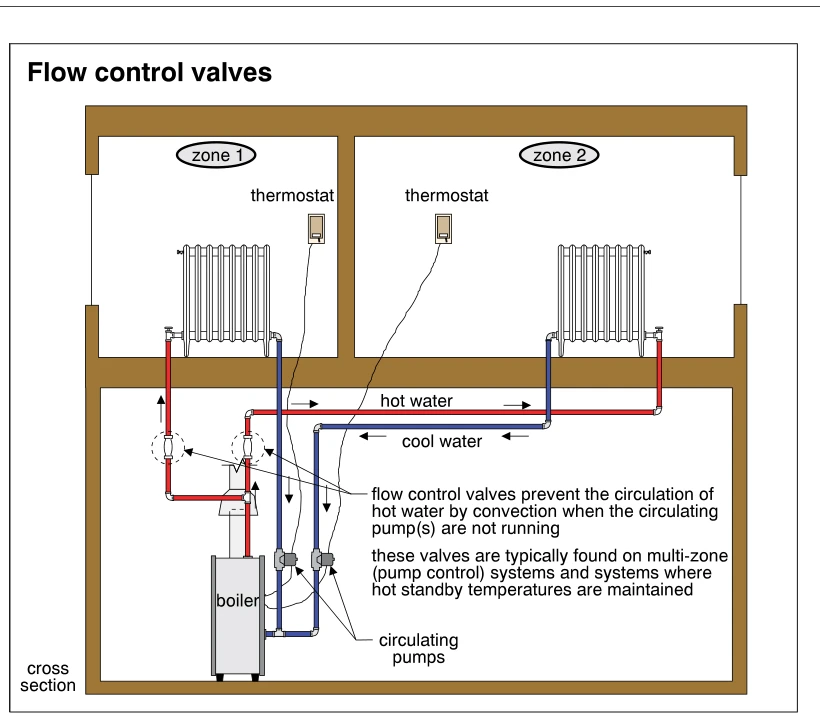 0887
0887Flow control valves
· p. 153
A building cross section depicts a two-zone hydronic heating system with a boiler below two rooms, each containing a radiator and thermostat. Red supply piping carries hot water to the radiators, while blue return piping carries cooler water back through separate circulating pumps. Flow control valves are highlighted in the supply branches, and arrows indicate water flow direction. The annotations explain that these valves prevent unwanted convection circulation when the pumps are not running and are typically used in multi-zone pump-controlled systems and systems maintained at hot standby temperatures.
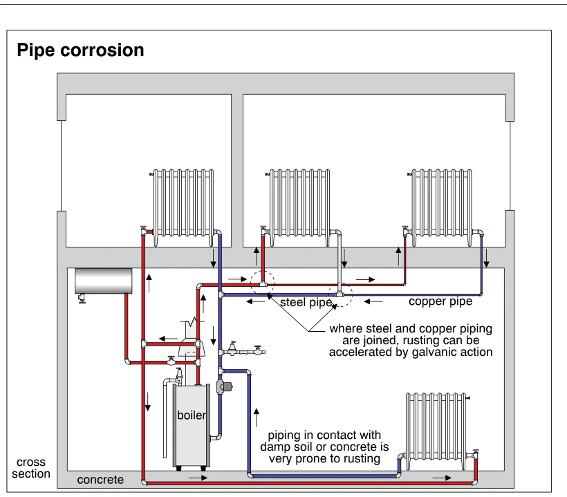 0888
0888Pipe corrosion
· p. 153
A building cross section shows a boiler and hot-water distribution piping serving three upper-level radiators and one basement radiator. Red and blue pipe runs and directional arrows indicate circulation through the system. Dashed circles highlight connections between steel and copper piping, where the annotation warns that galvanic action can accelerate rusting. Lower distribution pipes run in contact with the concrete floor, illustrating another location prone to rusting when damp.
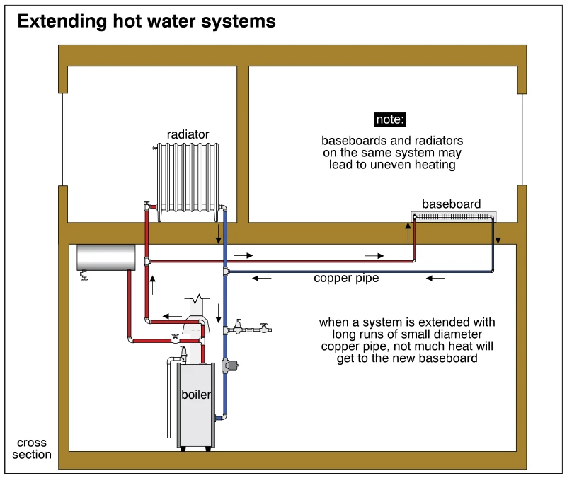 0889
0889Extending hot water systems
· p. 153
A building cross section shows a basement boiler supplying an upper-floor radiator and a baseboard heater through red supply and blue return piping. The baseboard is connected by long horizontal copper pipe runs branching from the radiator piping, with arrows indicating water flow. An annotation warns that extending a system with long runs of small-diameter copper pipe may deliver insufficient heat to the new baseboard. A second note warns that combining baseboards and radiators on the same system may lead to uneven heating.
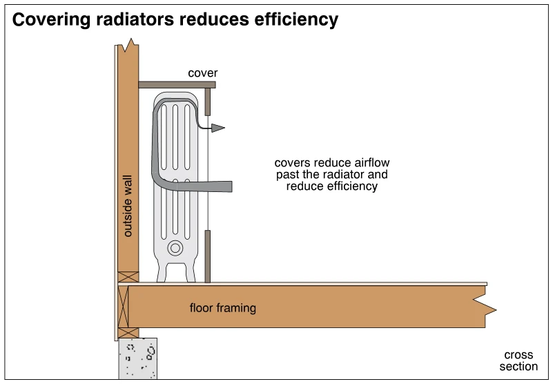 0890
0890Covering radiators reduces efficiency
· p. 153
A cross section shows a floor-standing radiator beside an outside wall, with a cover extending over its top and partially down its front. Arrows illustrate airflow passing around the radiator and out through the cover openings. The annotation identifies reduced airflow past the covered radiator as a cause of reduced heating efficiency. Floor framing and a portion of the supporting foundation are shown beneath the assembly.
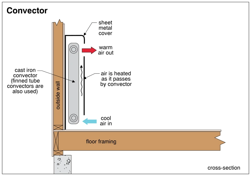 0891
0891Convector
· p. 153
The cross-section shows a cast iron hot-water convector mounted beside an outside wall, just above the floor. A sheet metal cover encloses the convector with openings at the bottom and top for airflow. Arrows show cool air entering at the bottom, rising as it is heated by the convector, and exiting as warm air near the top. The drawing also identifies the floor framing and notes that finned tube convectors are an alternative. No defect or improper installation is depicted.
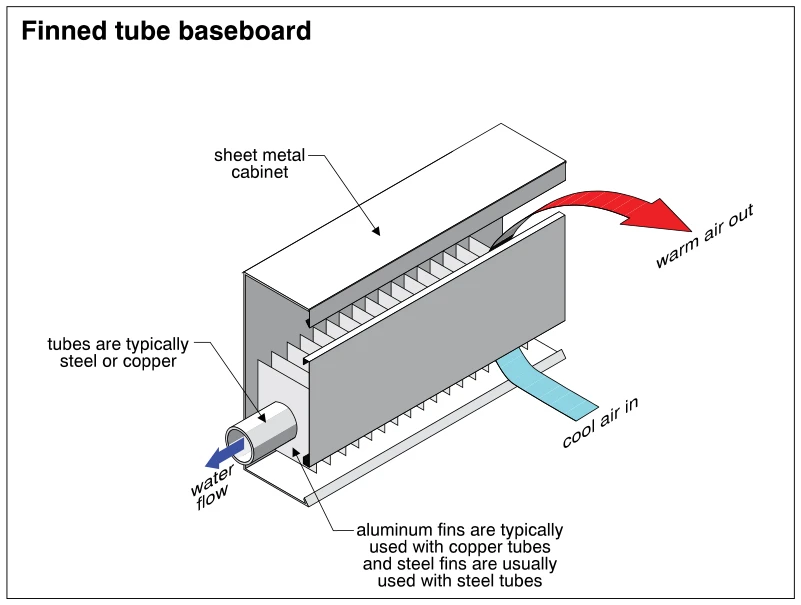 0892
0892Finned tube baseboard
· p. 153
The illustration shows a hydronic finned-tube baseboard heater with a sheet metal cabinet enclosing a tube and closely spaced heat-transfer fins. An exposed tube end and arrow indicate water flow through the heating element. Cool air enters beneath the cabinet, passes over the finned tube, and exits warm through the upper opening by natural convection. Annotations identify typical steel or copper tubes, with aluminum fins typically used on copper tubes and steel fins usually used on steel tubes. No defect or improper installation is depicted.
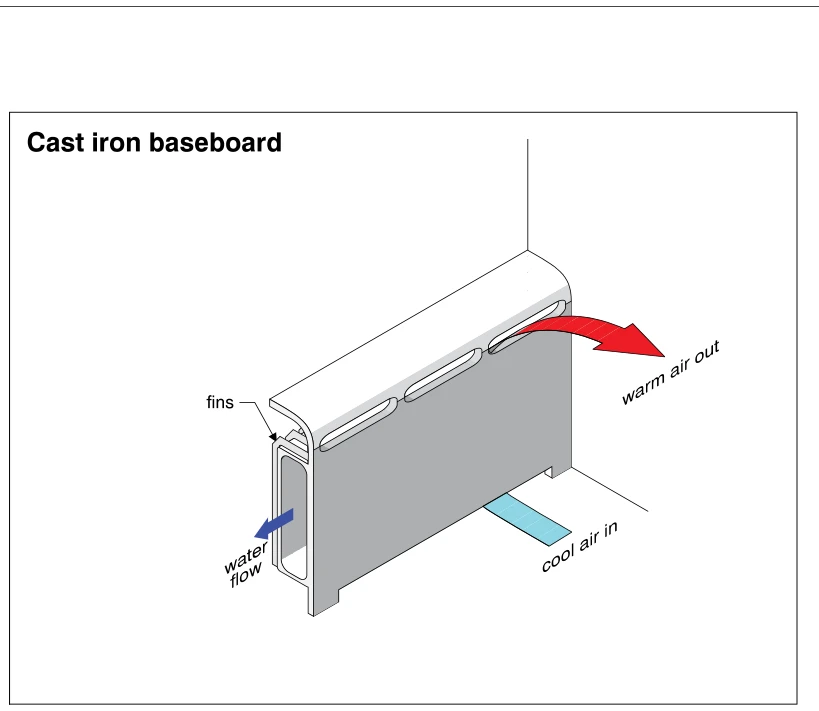 0893
0893Cast iron baseboard
· p. 154
The illustration shows a cast-iron baseboard radiator used in a hot-water heating system, with an exposed end section revealing its water passage and fins. A blue arrow identifies water flow through the radiator. Cool room air enters beneath the unit, passes over the heated surfaces, and exits through openings along the top as warm air. The diagram illustrates normal heat distribution by convection; no defects are depicted.
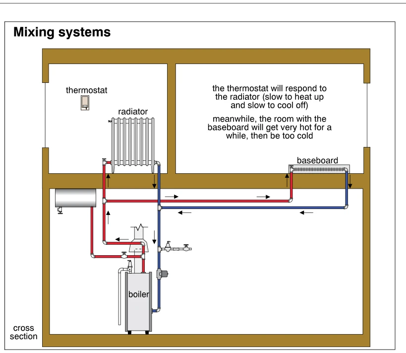 0894
0894Mixing systems
· p. 154
A house cross section shows a basement boiler supplying a radiator in one room and a finned baseboard heater in an adjacent room. Red supply piping and blue return piping connect both emitters to the boiler, with arrows indicating water circulation. The thermostat is located in the room with the radiator. The annotations explain that the thermostat responds to the radiator's slow heating and cooling, while the room with the baseboard becomes very hot and then too cold. The illustration highlights uneven temperature control when emitters with different thermal response characteristics share a thermostat.
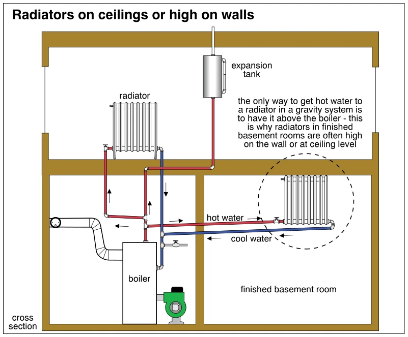 0895
0895Radiators on ceilings or high on walls
· p. 154
A building cross section shows a gravity hot-water heating system serving an upper-floor radiator and a radiator mounted high in a finished basement room. Red supply piping and blue return piping, with directional arrows, show hot water flowing to the radiators and cooler water returning to the basement boiler. An expansion tank is connected above the upper floor. The basement radiator is highlighted with a dashed circle and is positioned above the boiler. The annotation explains that gravity circulation requires radiators to be above the boiler, accounting for high-wall or ceiling-level placement in finished basements.
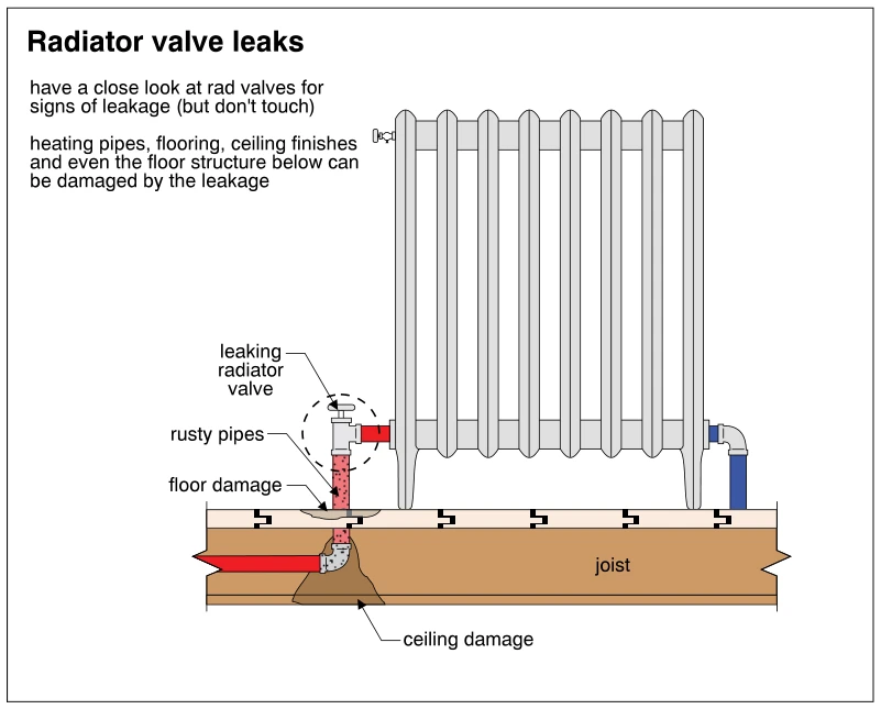 0896
0896Radiator valve leaks
· p. 154
A freestanding hot-water radiator is shown above a cutaway floor assembly, with piping connected at both lower ends. A dashed circle highlights a leaking radiator valve on the left connection, and the pipe below it is marked as rusty. Damage is shown around the pipe penetration in the flooring and extending down to the ceiling finish below, beside a labeled joist. The annotations advise visually checking radiator valves for leakage without touching them and warn that leaks can damage piping, flooring, ceiling finishes, and floor structure.
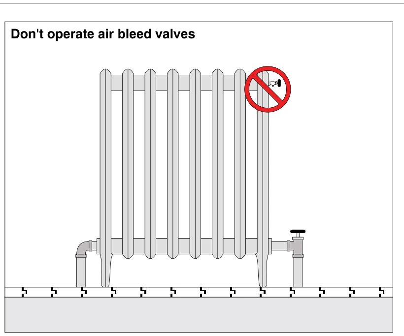 0897
0897Don't operate air bleed valves
· p. 155
The illustration shows a floor-standing sectional radiator connected to heating pipes at both lower ends. A hand-operated valve is installed on the lower right pipe connection. A small air bleed valve at the upper right of the radiator is overlaid with a red prohibition symbol. The figure warns against operating air bleed valves during inspection; it does not depict a visible radiator defect.
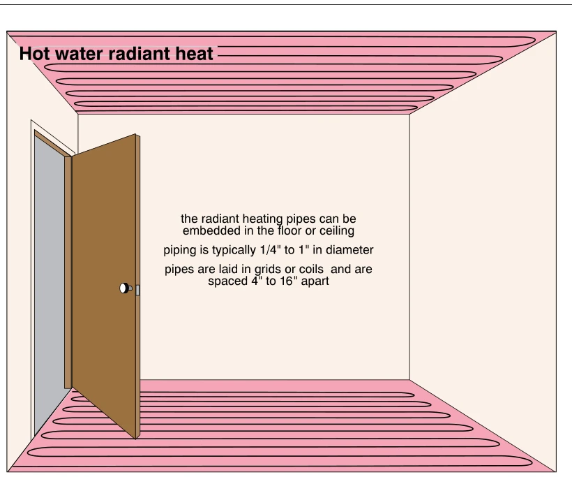 0898
0898Hot water radiant heat
· p. 155
The illustration shows a room with hot-water radiant heating pipes represented in both the floor and ceiling. The pipes follow repeated serpentine loops across the surfaces. Annotations explain that the pipes can be embedded in either the floor or ceiling, typically measure 1/4 inch to 1 inch in diameter, and are laid in grids or coils spaced 4 to 16 inches apart. No defects or improper installation practices are depicted.
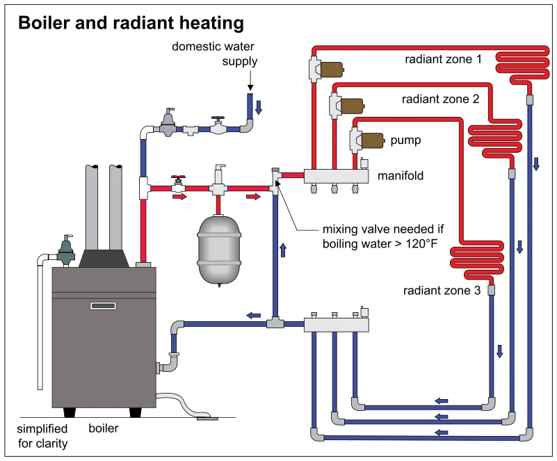 0898.1
Boiler and radiant heating
· p. 155
This simplified schematic depicts a boiler supplying three radiant heating zones through a supply manifold, with a separate circulator pump on each zone branch. Red piping carries heated water to the serpentine radiant loops, and blue piping returns water through a common return manifold to the boiler; arrows indicate flow direction. A domestic water supply connects to the heating circuit, and an expansion tank hangs from the supply piping near the boiler. A connection between the supply and return piping is identified as requiring a mixing valve if the water temperature exceeds 120°F.
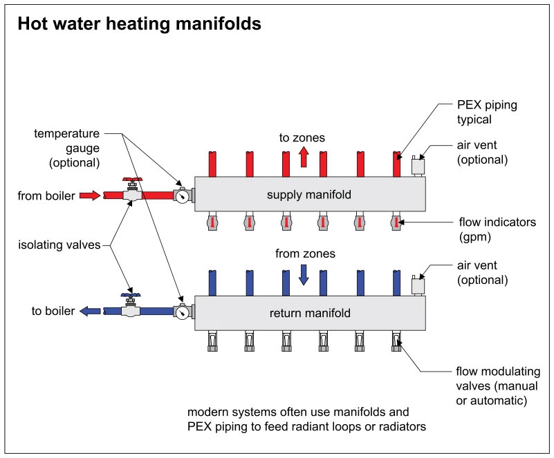 0898.2
Hot water heating manifolds
· p. 155
The diagram shows paired supply and return manifolds for a hot water heating distribution system, each with six zone connections. Red piping carries water from the boiler into the supply manifold and out to the zones, while blue piping brings water from the zones into the return manifold and back to the boiler. Both boiler connections have isolating valves and optional temperature gauges, and each manifold has an optional air vent. The supply manifold has flow indicators marked in gallons per minute, while the return manifold has manual or automatic flow modulating valves. An annotation identifies PEX piping as typical and notes that manifolds feed radiant loops or radiators.
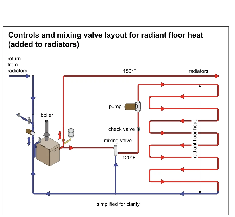 0898.5
Controls and mixing valve layout for radiant floor heat (added to radiators)
· p. 156
This schematic shows a boiler serving radiators with an added radiant floor heating circuit. The radiator supply is labeled 150°F, while a mixing valve combines boiler supply water with cooler return water to provide a 120°F supply to the floor circuit. A check valve and pump are installed downstream of the mixing valve before the serpentine radiant floor tubing. Red and blue piping and directional arrows identify the supply and return flow paths, with the floor return connected back to the boiler and to the mixing valve. The layout is explicitly simplified for clarity and depicts no identified defects.
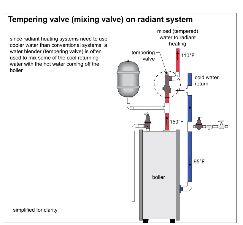 0899
0899Tempering valve (mixing valve) on radiant system
· p. 156
This simplified hydronic radiant-heating schematic shows a tempering valve blending hot boiler supply water with cooler return water. The boiler supply is labeled 150°F, the return 95°F, and the mixed supply to the radiant heating 110°F. Arrows show upward hot-water flow, downward return flow, and a branch carrying return water into the mixing valve. An expansion tank connects to the boiler supply piping, and ancillary valves and piping are shown beside the boiler. The annotation explains that radiant heating requires cooler water than conventional heating systems.
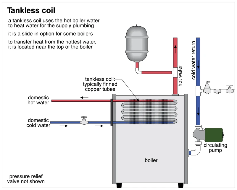 0900
0900Tankless coil
· p. 156
The cutaway diagram shows a tankless domestic water-heating coil installed near the top of a hydronic boiler. Domestic cold water enters the lower end of the finned coil and leaves the upper end as domestic hot water, absorbing heat from the surrounding boiler water without mixing with it. Separate heating-system piping carries hot water upward from the boiler and returns cooler water through a circulating pump. An expansion tank is connected to the hot-water piping above the boiler. The annotations describe the coil as a slide-in option for some boilers and explicitly state that the pressure relief valve is not shown.
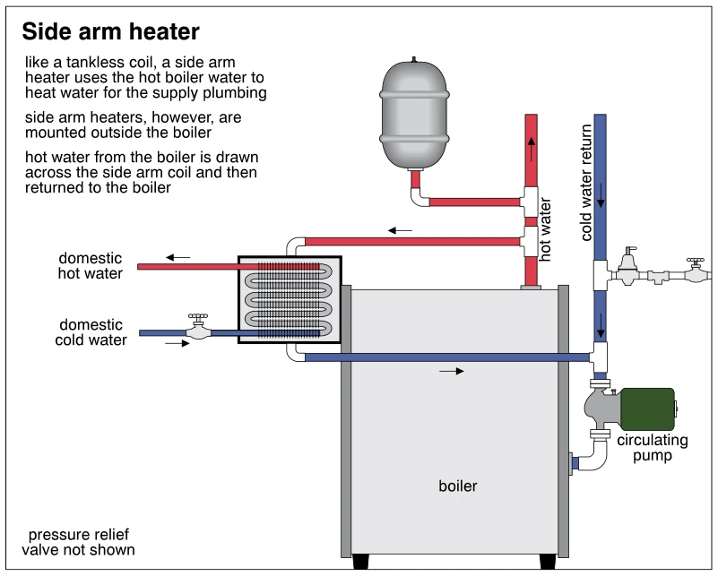 0901
0901Side arm heater
· p. 156
The diagram depicts a hydronic boiler with an externally mounted side arm heater for domestic hot water. Hot boiler water flows from the supply piping through the side arm heater, across the domestic-water coil, and back to the boiler return. Domestic cold water enters the bottom of the coil and exits as domestic hot water at the top, separate from the boiler-water circuit. Red and blue piping and directional arrows distinguish the hot supply and cooler return paths. An expansion tank connects to the hot-water piping, and a circulating pump is installed on the boiler return; an annotation states that the pressure relief valve is not shown.
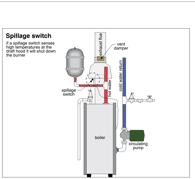 0902
0902Spillage switch
· p. 157
The illustration shows a hot-water heating boiler with a draft hood, exhaust flue, and vent damper above it. A spillage switch is highlighted at the lower edge of the draft hood, with wiring extending toward the boiler. The annotation explains that high temperatures sensed at the draft hood cause the switch to shut down the burner. Red hot-water piping connects to an expansion tank, while blue return piping connects to a circulating pump at the side of the boiler. Additional valves and a downward discharge pipe are shown alongside the boiler.
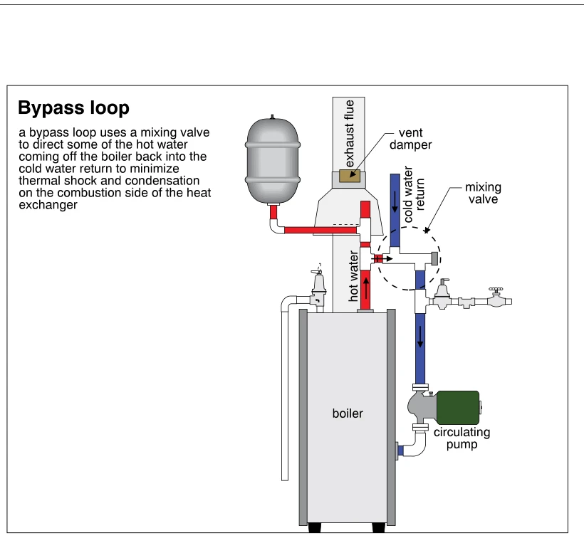 0903
0903Bypass loop
· p. 157
The illustration shows a hydronic heating boiler with a bypass connection between its hot-water outlet and cold-water return. A mixing valve, highlighted by a dashed circle, directs some outgoing hot water into the return piping before it passes through the circulating pump and enters the boiler. Red and blue pipe sections and arrows indicate hot supply water and cooler return water and their flow directions. The annotation explains that this arrangement minimizes thermal shock and condensation on the combustion side of the heat exchanger. An expansion tank, exhaust flue with vent damper, relief valve with discharge piping, and a valved water-feed connection are also shown.
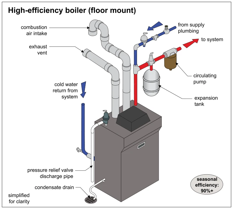 0903.1
High-efficiency boiler (floor mount)
· p. 157
The illustration shows a floor-mounted high-efficiency boiler with separate combustion air intake and exhaust vent piping. Blue piping indicates cold water returning from the heating system and makeup water entering from the supply plumbing, while red piping carries heated water to the system through a circulating pump. An expansion tank connects to the heating-water piping above the boiler. A pressure relief valve discharge pipe runs down the side of the cabinet, and a condensate drain leads to a floor drain. The simplified assembly is labeled with a seasonal efficiency of 90% or greater; no defects are identified.
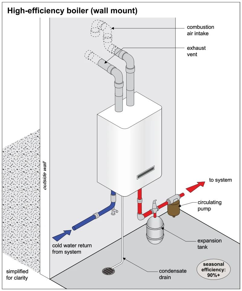 0903.2
High-efficiency boiler (wall mount)
· p. 157
The illustration shows a wall-mounted high-efficiency boiler with separate combustion air intake and exhaust vent pipes routed through an outside wall. A blue pipe carries cold return water from the heating system to the boiler, while a red supply pipe carries heated water back to the system through a circulating pump. An expansion tank connects to the supply piping below the boiler. A condensate drain runs from the bottom of the boiler to a floor drain. The diagram states a seasonal efficiency of 90%+ and is simplified for clarity; no defects are identified.
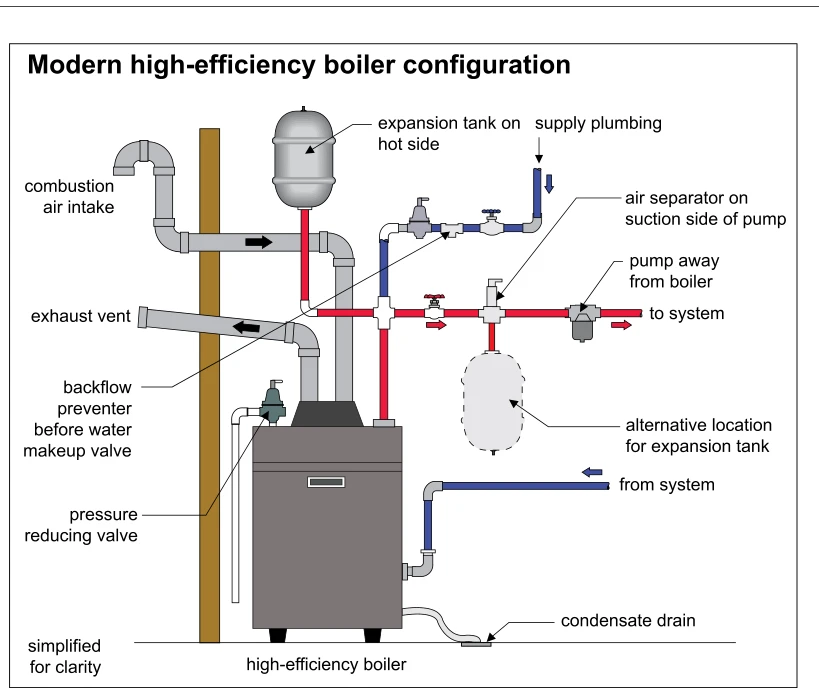 0903.3
Modern high-efficiency boiler configuration
· p. 158
The schematic shows a high-efficiency boiler with separate combustion air intake and exhaust vent piping, and a condensate drain at its base. Red piping carries heated water from the boiler to the system, while blue piping returns water from the system. An expansion tank connects to the hot side, with an alternative tank location shown beneath the air separator. The air separator is on the suction side of the circulator pump, which pumps away from the boiler toward the system. Makeup water supply plumbing includes a backflow preventer before the water makeup valve, and a separate boiler-mounted valve is labeled as a pressure reducing valve.
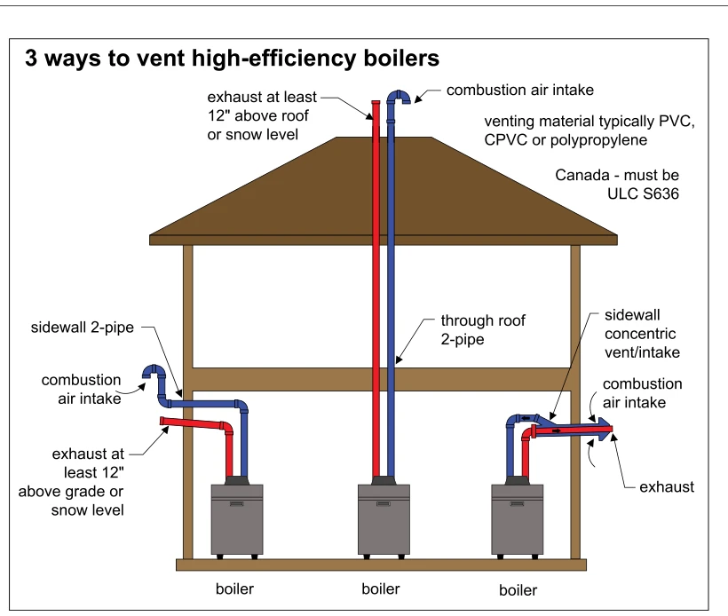 0903.4
3 ways to vent high-efficiency boilers
· p. 158
A schematic house section shows three high-efficiency boilers with alternative exhaust and combustion-air piping arrangements. The left boiler uses separate sidewall pipes, with a downturned combustion-air intake and an exhaust labeled to terminate at least 12 inches above grade or snow level. The center boiler uses separate pipes through the roof, with a downturned intake and an exhaust labeled to extend at least 12 inches above the roof or snow level. The right boiler uses a sidewall concentric vent/intake termination that combines the two air paths at a single wall penetration. Red identifies exhaust paths and blue identifies combustion-air intake paths; annotations list typical plastic vent materials and the Canadian ULC S636 requirement.
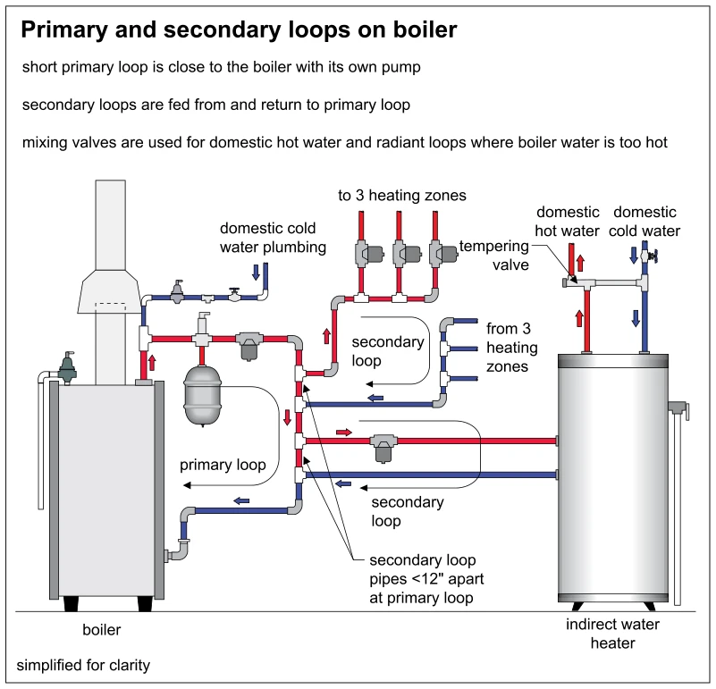 0903.5
Primary and secondary loops on boiler
· p. 158
This schematic shows a boiler with a short, pumped primary loop supplying secondary circuits for three heating zones and an indirect water heater. Red supply pipes, blue return pipes, and arrows indicate water flow through the circuits. Secondary supply and return connections are identified as less than 12 inches apart at the primary loop. The indirect water heater has separate domestic cold-water and hot-water connections, with a tempering valve connecting the cold supply to the hot outlet. An expansion tank, circulators, valves, and boiler vent are also shown.
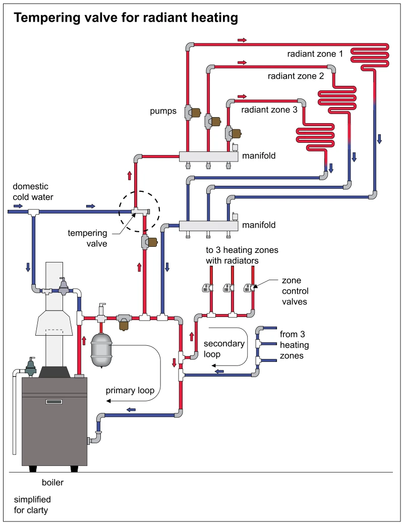 0903.6
Tempering valve for radiant heating
· p. 158
The schematic depicts a boiler serving three radiant heating zones and three heating zones with radiators. A circled tempering valve connects the domestic cold-water line to the hot supply feeding the radiant distribution manifold. Three individual pumps circulate water through the radiant coils, which return to a separate manifold. The radiator branch is shown as a secondary loop with three zone control valves connected to the boiler's primary loop. Red and blue piping and directional arrows distinguish hot supply and cooler return flow; an expansion tank and boiler vent connection are also shown.
Hot Water Boilers (Hydronic Heating) ·Pulse Combustionp. 159
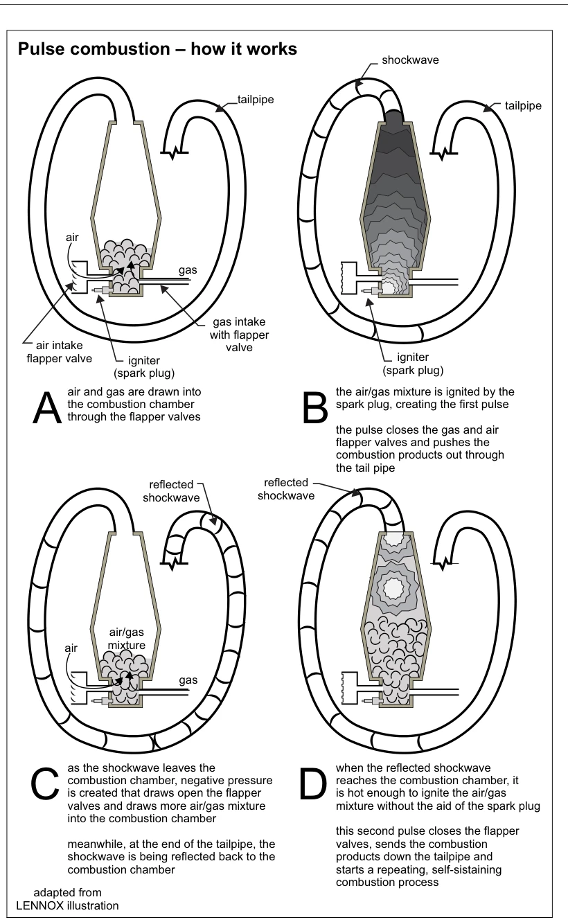 0904
0904Pulse combustion – how it works
· p. 159
Four sequential diagrams show the operating cycle of a pulse-combustion heating assembly with a combustion chamber, air and gas intake flapper valves, spark-plug igniter, and curved tailpipe. In stage A, air and gas enter the chamber through the flapper valves. In stage B, spark ignition produces a pressure pulse that closes the valves and pushes combustion products through the tailpipe. Stage C shows negative pressure reopening the valves to admit a fresh mixture while a shockwave reflects from the end of the tailpipe. In stage D, the returning hot shockwave ignites the mixture without the spark plug, repeating the combustion cycle.
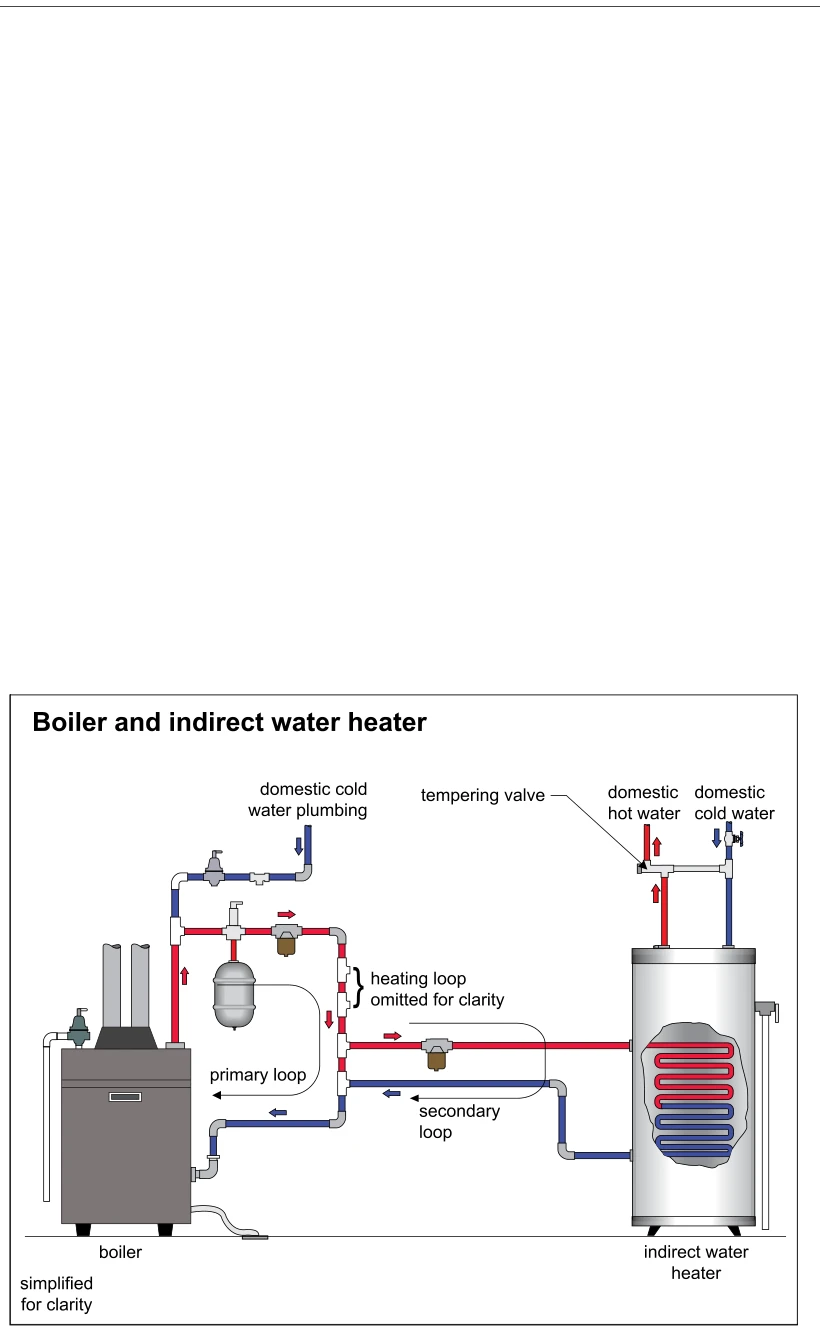 0905
0905Boiler and indirect water heater
· p. 159
The schematic shows a boiler connected to an indirect domestic water heater through primary and secondary hydronic loops. Red and blue piping and directional arrows distinguish heated supply water from cooler return water. A cutaway in the storage tank exposes a coiled heat exchanger that transfers heat from boiler water to domestic water without mixing the two. Domestic cold water enters at the top of the tank, and a tempering valve connects the hot-water outlet to the cold-water supply. An expansion tank, circulators, valves, and boiler makeup-water connection are also shown; the space-heating loop is explicitly omitted for clarity.
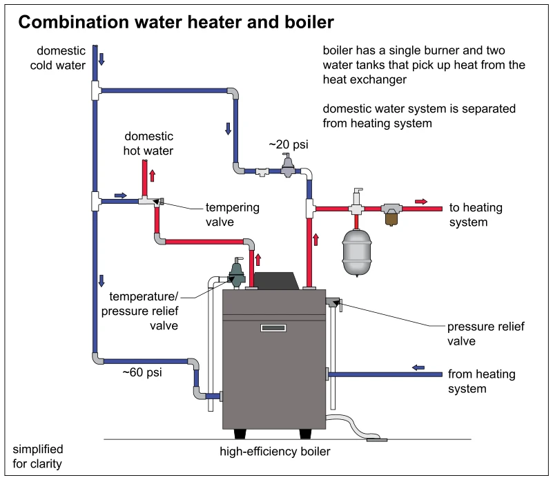 0906
0906Combination water heater and boiler
· p. 159
The schematic depicts a high-efficiency combination boiler and domestic water heater with a single burner and two separate water tanks heated by a heat exchanger. Blue piping supplies domestic cold water at approximately 60 psi, while a branch supplies the heating circuit through a pressure-reducing arrangement labeled approximately 20 psi. A tempering valve mixes cold water with the domestic hot-water outlet. The separate heating circuit includes supply and return piping, an expansion tank, and a pressure relief valve; the domestic side has a temperature/pressure relief valve. Red and blue piping and directional arrows distinguish hot supply flows from cold-water and heating-return flows.
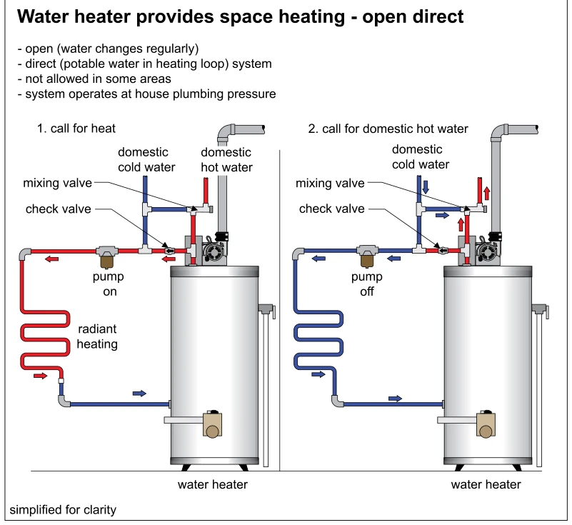 0908
0908Water heater provides space heating - open direct
· p. 159
Two schematics depict an open-direct system in which a storage water heater supplies both domestic hot water and radiant space heating using potable water at house plumbing pressure. During a call for heat, the circulating pump is on, and arrows show heated water passing through the radiant heating loop and returning to the water heater. During a call for domestic hot water, the pump is off, and cold-water arrows show incoming water flowing through the heating loop toward the tank while hot water exits toward the domestic supply. Both diagrams identify a mixing valve and a check valve at the piping connections above the heater. The annotations state that water changes regularly and that this arrangement is not allowed in some areas.
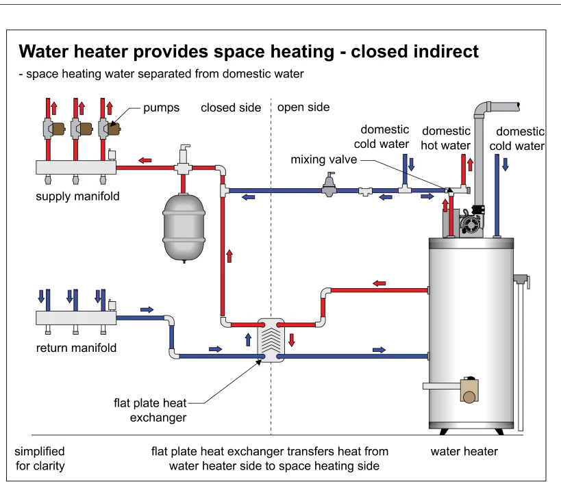 0909
0909Water heater provides space heating - closed indirect
· p. 160
The schematic shows a storage water heater providing domestic hot water and space heating through a flat plate heat exchanger. A dashed line separates the closed space-heating circuit from the open domestic-water side, with heat transferred between the circuits without mixing their water. The closed circuit includes supply and return manifolds, multiple pumps, and an expansion tank. Red and blue piping with arrows illustrates heated supply and cooler return flows through the exchanger. Domestic hot and cold water connections and a mixing valve are shown above the water heater, along with its vent and side-mounted discharge piping.
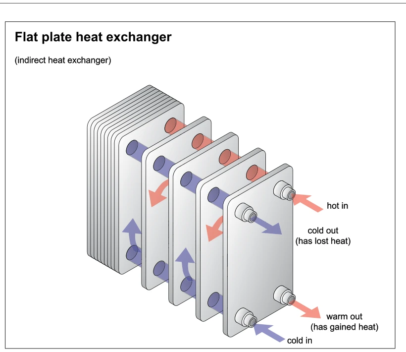 0910
0910Flat plate heat exchanger
· p. 160
An exploded perspective shows a flat plate indirect heat exchanger with a stack of closely spaced plates and four pipe connections on the front plate. Colored arrows illustrate two separate fluid paths through alternating spaces between the plates. The hot stream enters at the upper right and exits through the upper left connection after losing heat. The cold stream enters at the lower left and exits at the lower right after gaining heat. Heat transfers across the separating plates without the two streams mixing; no defect or improper installation is depicted.
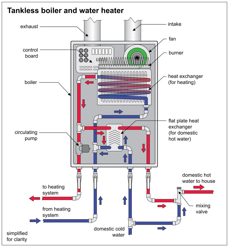 0911
0911Tankless boiler and water heater
· p. 160
This simplified cutaway depicts a tankless boiler supplying both space heating and domestic hot water. A fan and burner sit above the heating heat exchanger, with intake and exhaust connections at the top of the cabinet. Red and blue piping and directional arrows show heated water flowing to the heating system and cooler water returning, with a circulating pump in the boiler circuit. A separate flat plate heat exchanger transfers heat to incoming domestic cold water. An external mixing valve blends cold water with the domestic hot-water outlet before delivery to the house.
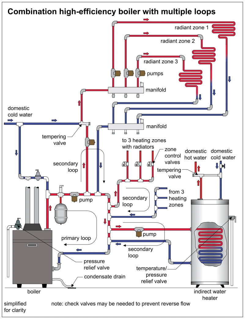 0912
0912Combination high-efficiency boiler with multiple loops
· p. 160
The schematic depicts a high-efficiency boiler serving multiple hydronic heating loops and an indirect domestic water heater through primary-secondary piping. Three radiant heating zones have individual pumps and shared supply and return manifolds, while another secondary loop connects to three radiator zones with zone control valves. A pumped secondary loop circulates boiler water through a heat-exchanger coil inside the indirect water heater. Red and blue piping and directional arrows distinguish heated supply and cooler return flows; domestic cold-water connections and tempering valves are also shown. The boiler has a pressure relief valve and condensate drain, and the water heater has a temperature/pressure relief valve. A note states that check valves may be needed to prevent reverse flow.
Chimneys ·Introductionp. 161
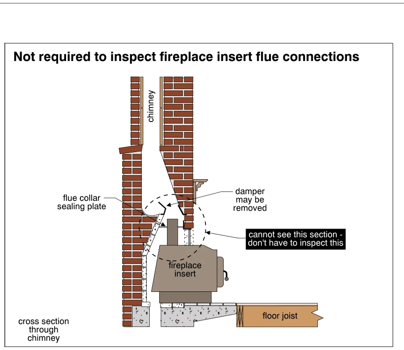 0950
0950Not required to inspect fireplace insert flue connections
· p. 161
The illustration shows a cross section through a masonry chimney and fireplace containing a fireplace insert. The insert sits on the hearth, with its flue outlet extending upward toward the fireplace throat. Callouts identify a flue collar sealing plate and note that the damper may be removed. A dashed circle highlights the concealed connection area above the insert, with an annotation stating that this unseen section does not have to be inspected. A floor joist is shown adjacent to the hearth support.
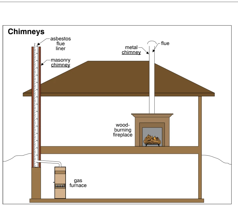 0951
0951Chimneys
· p. 161
A schematic house section shows two chimney arrangements serving separate heating appliances. A gas furnace in the basement connects through a vent connector to a masonry chimney along the exterior wall. The masonry chimney contains a labeled asbestos flue liner and extends above the roof. A wood-burning fireplace on the floor above has a metal chimney rising vertically through the roof, with its interior passage labeled as the flue. No specific installation defect is identified.
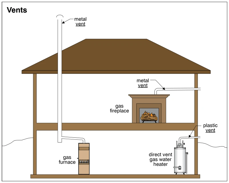 0952
0952Vents
· p. 161
A schematic house section shows vent arrangements for three gas-fired appliances. A basement gas furnace connects to a metal vent that rises vertically through the house and terminates above the roof. A gas fireplace on the floor above connects to a metal vent that turns horizontally and exits through an exterior wall. A basement direct vent gas water heater connects to a plastic vent that turns and passes through the exterior wall above grade. The illustration identifies vent materials and routes without depicting installation defects.
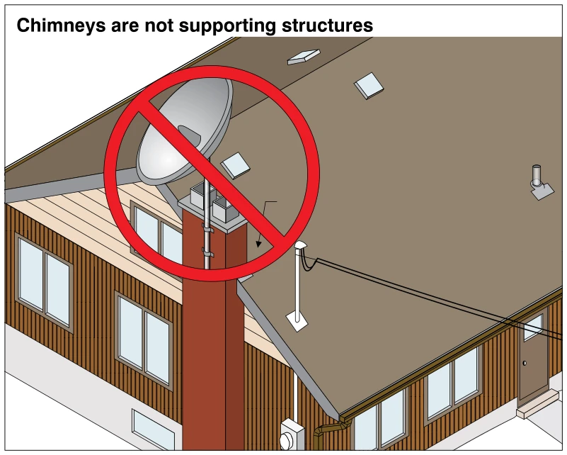 0953
0953Chimneys are not supporting structures
· p. 161
The illustration shows a satellite dish mounted on a mast fastened to the exterior chimney of a house. A large red prohibition symbol overlays the dish and chimney, identifying this use of the chimney as an equipment support as improper. The chimney extends above the sloped roof and has two flue openings at its top. Roof vents, a plumbing vent pipe, and an electrical service mast with overhead wires are also visible.
Chimneys ·Masonry Chimneysp. 162
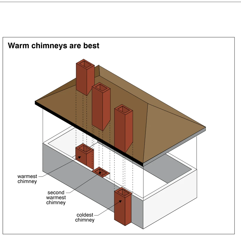 0954
0954Warm chimneys are best
· p. 162
An exploded perspective of a house compares three masonry chimney locations relative to the building enclosure. Dashed lines connect the lower chimney sections to their extensions above the roof. The chimney located within the house is labeled the warmest, the chimney within the exterior wall is labeled second warmest, and the chimney projecting outside the exterior wall is labeled coldest. The illustration presents interior chimney placement as preferable for keeping a chimney warm.
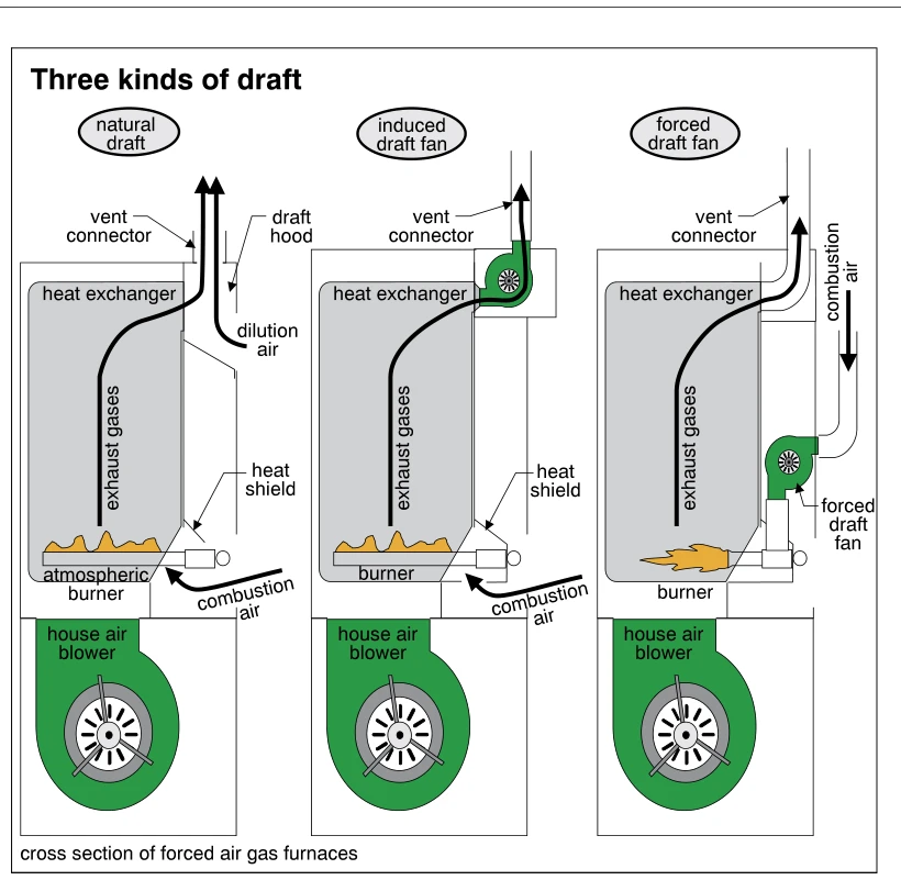 0955
0955Three kinds of draft
· p. 162
Three cross sections compare natural, induced, and forced draft arrangements in forced-air gas furnaces. Each shows a burner, heat exchanger, vent connector, and separate house air blower beneath the heating assembly. The natural-draft arrangement includes an atmospheric burner and a draft hood admitting dilution air to the exhaust stream. The induced-draft arrangement places a fan at the heat exchanger outlet to draw exhaust gases toward the vent connector. The forced-draft arrangement places a fan on the combustion-air inlet to push air toward the burner, with exhaust gases leaving through the upper vent connector.
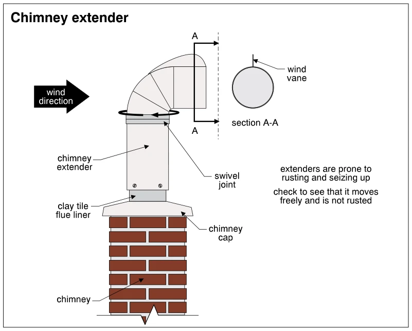 0956
0956Chimney extender
· p. 162
The illustration shows a chimney extender fitted over a clay tile flue liner projecting through the cap of a brick masonry chimney. The extender has a swivel joint and a curved upper outlet oriented away from the indicated wind direction. A circular arrow indicates rotation, and section A-A shows the wind vane attached to the outlet. An annotation warns that extenders are prone to rusting and seizing and advises checking for free movement and absence of rust.
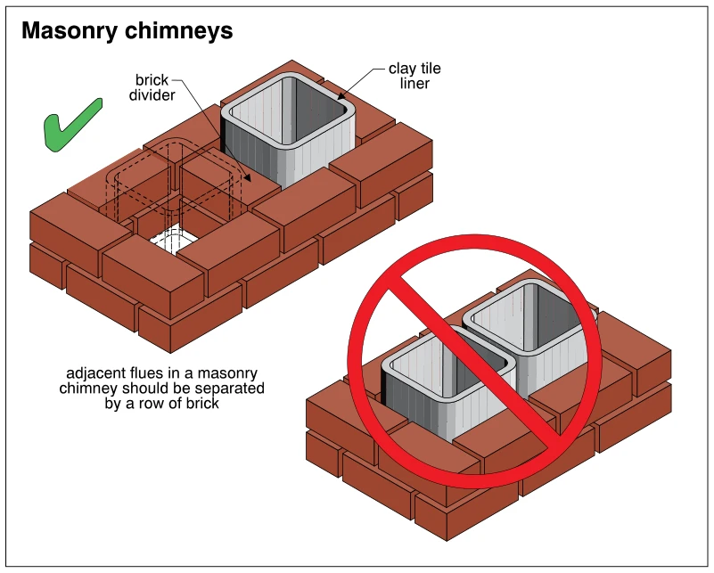 0957
0957Masonry chimneys
· p. 162
The illustration compares two arrangements of adjacent clay tile flue liners within a brick masonry chimney. The correct arrangement, marked with a green check, has a row of brick separating the flues; one liner is shown in dashed outline to reveal the divider. The incorrect arrangement, marked with a red prohibition symbol, places the two liners next to each other without a brick divider. Both views show the liners enclosed by exterior courses of brick.
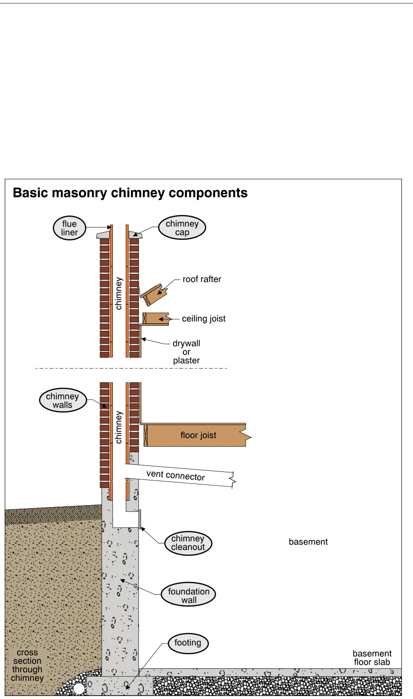 0958
0958Basic masonry chimney components
· p. 163
The illustration presents a vertical cross section of a masonry chimney from its footing to its cap, with a break in the drawing between upper and lower portions. Brick chimney walls surround a flue liner that projects above the chimney cap. Roof, ceiling, and floor framing are shown adjacent to the chimney, along with drywall or plaster. A vent connector enters the flue near the basement, with a chimney cleanout below the connection. The lower portion shows the foundation wall and footing beside the basement floor slab and exterior soil; no specific defect is identified.
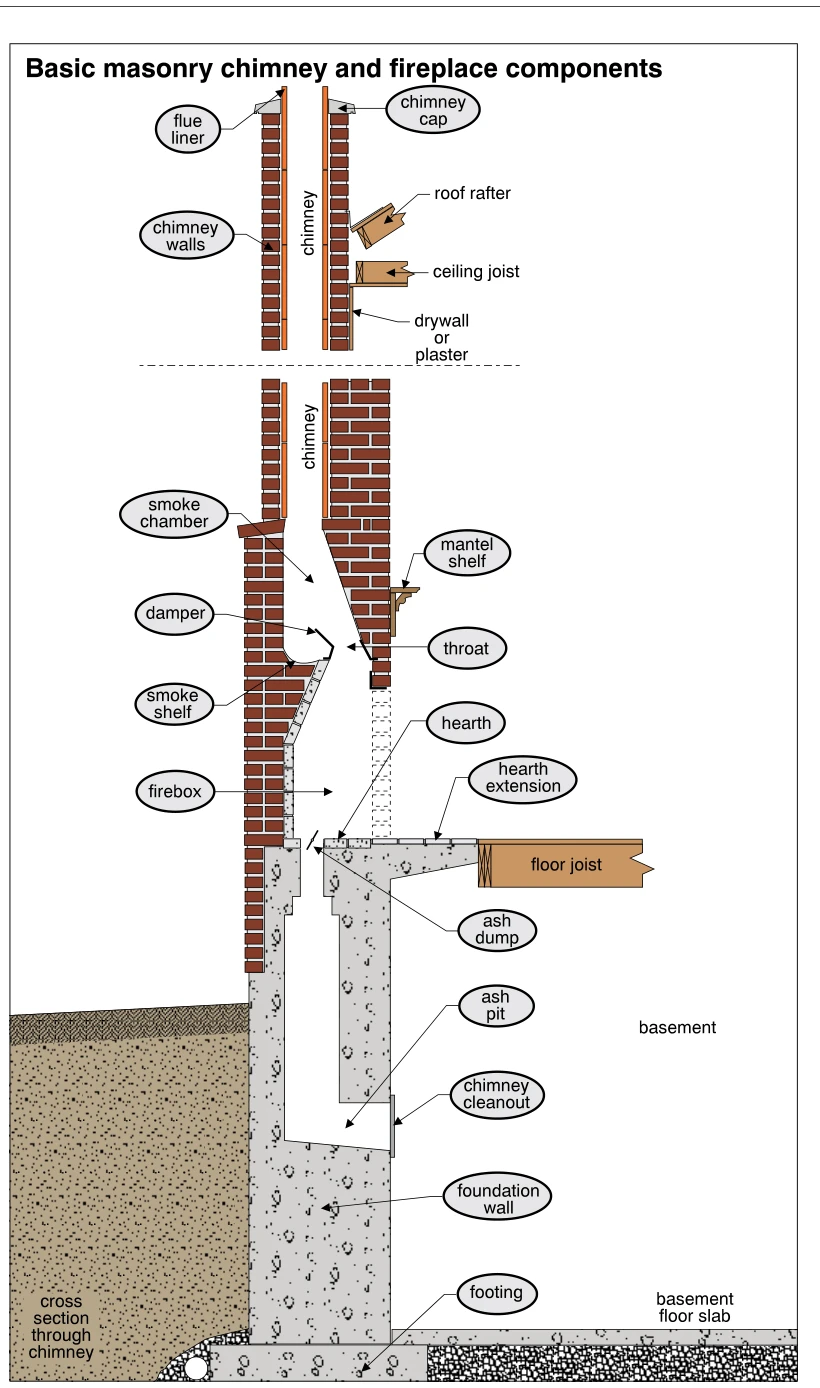 0959
0959Basic masonry chimney and fireplace components
· p. 163
The illustration shows a cross section through a masonry fireplace and chimney, from the foundation footing to the chimney cap. The firebox opens through a throat and damper into the smoke chamber, which narrows into the lined chimney flue; a smoke shelf sits behind the damper. The hearth and hearth extension are shown at floor level, with a mantel shelf above the fireplace opening and a floor joist adjoining the hearth support. An ash dump leads into an ash pit below the firebox, with a cleanout accessible from the basement. The upper chimney section shows masonry walls and a flue liner beside a roof rafter, ceiling joist, and drywall or plaster, while the lower section shows the foundation wall, footing, and adjacent basement slab.
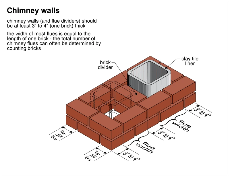 0960
0960Chimney walls
· p. 163
An oblique cutaway view shows a brick masonry chimney with two flue openings separated by a brick divider. One clay tile liner projects above the masonry, while dashed outlines indicate the other liner. Dimension arrows identify the exterior walls and flue divider as 3 to 4 inches thick, and braces mark the flue widths. The annotations state that chimney walls and dividers should be at least one brick thick and that flue widths commonly equal the length of one brick, allowing the number of flues to be estimated by counting bricks.
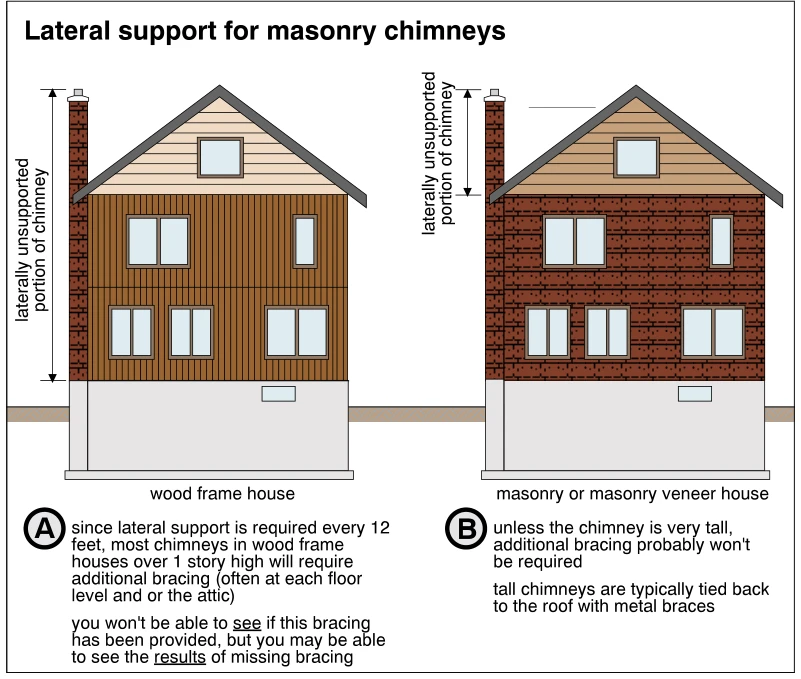 0961
0961Lateral support for masonry chimneys
· p. 163
Two house elevations compare lateral support conditions for exterior masonry chimneys on a wood frame house and a masonry or masonry veneer house. On the wood frame house, a dimension arrow identifies the laterally unsupported chimney length from the top of the foundation to the chimney top. On the masonry or masonry veneer house, the unsupported length is marked only above the eave. Notes state that lateral support is required every 12 feet and that wood frame houses over one story generally require additional chimney bracing, which may be concealed. The masonry-house notes explain that additional bracing is generally unnecessary unless the chimney is very tall, and that tall chimneys are typically tied back to the roof with metal braces; the braces themselves are not illustrated.
 0962
0962Clay tile flue liners
· p. 164
The illustration shows a section through a masonry chimney with a clay tile flue liner extending above the chimney cap. A typical liner cross section is square with rounded corners, and individual sections are noted as usually 2 to 3 feet long. An enlarged detail shows a 3/4 inch gap between the liner and the surrounding chimney masonry. The liner joints are specified to use refractory mortar and to be smooth on the inside of the liner. Adjacent roof rafter, ceiling joist, and wall framing are shown for context.
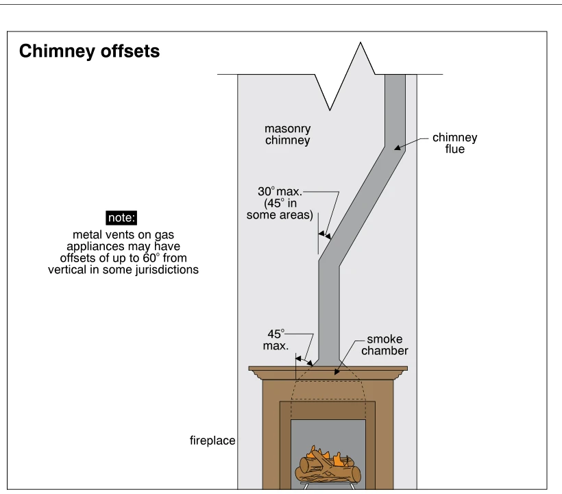 0963
0963Chimney offsets
· p. 164
The illustration shows a fireplace and smoke chamber beneath a masonry chimney containing an offset flue. Two vertical sections of flue are joined by a sloping section, with its angle from vertical labeled 30° maximum, or 45° in some areas. The smoke chamber narrows toward the flue and is marked with a 45° maximum slope from vertical. A separate note states that metal vents on gas appliances may have offsets up to 60° from vertical in some jurisdictions.
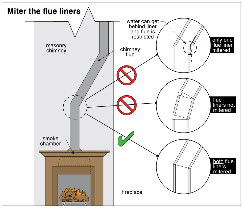 0964
0964Miter the flue liners
· p. 164
The illustration shows a fireplace and smoke chamber beneath a masonry chimney with an offset flue. Three enlarged details compare flue-liner joints where the flue changes direction. Mitering only one liner is marked incorrect, with an annotation showing that water can get behind the liner and the flue is restricted. Leaving both liner ends unmitered is also marked incorrect. Mitering both adjoining liner ends to form a matching angled joint is marked correct.
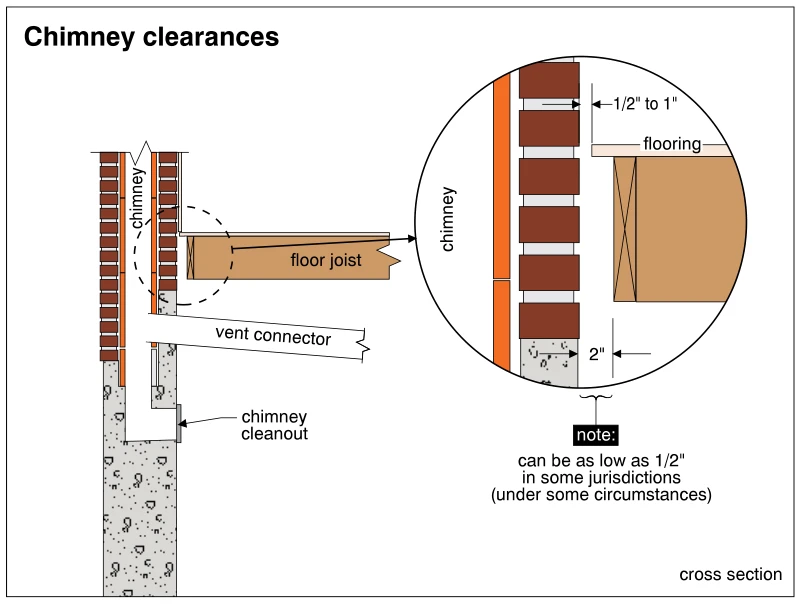 0965
0965Chimney clearances
· p. 164
The illustration shows a cross section of a masonry chimney beside a wood floor assembly, with a vent connector entering the chimney above a cleanout. An enlarged detail shows the separation between the chimney masonry, flooring edge, and floor joist. The flooring clearance is labeled 1/2 inch to 1 inch, while the clearance to the joist is labeled 2 inches. A note qualifies the 2-inch clearance as potentially as low as 1/2 inch in some jurisdictions under some circumstances.
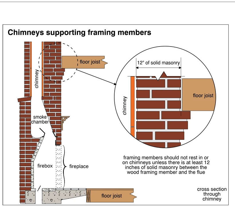 0966
0966Chimneys supporting framing members
· p. 165
The illustration shows a cross section through a masonry fireplace and chimney, including the firebox, smoke chamber, and adjacent floor joists. An upper wood floor joist bears on a projecting masonry course at the chimney. A circular enlargement shows 12 inches of solid masonry separating the joist end from the flue. The annotation states that framing members should not rest in or on chimneys unless at least this thickness of solid masonry separates the wood framing from the flue.
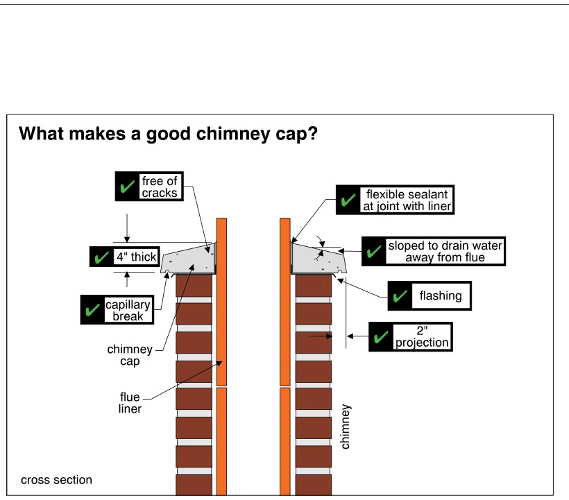 0967
0967What makes a good chimney cap?
· p. 165
The illustration shows a cross section of a masonry chimney with a projecting cap surrounding a flue liner that extends above it. Green check marks identify desirable cap details: freedom from cracks, a 4-inch thickness, and a top surface sloped to drain water away from the flue. The cap projects 2 inches beyond the chimney masonry and has a capillary break beneath its outer edge. Flashing is shown beneath the cap, and flexible sealant closes the joint between the cap and the flue liner.
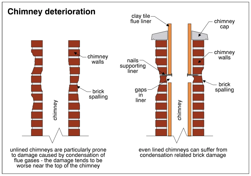 0968
0968Chimney deterioration
· p. 165
Two sectional diagrams show deterioration of brick masonry chimneys, one unlined and one with a clay tile flue liner. The unlined chimney has spalling along its walls, with an annotation explaining that condensation of flue gases causes damage that tends to be worse near the top. The lined chimney shows a chimney cap, gaps between liner sections, and nails supporting the liner. Brick spalling is shown adjacent to the liner gaps, illustrating that lined chimneys can also suffer condensation-related masonry damage.
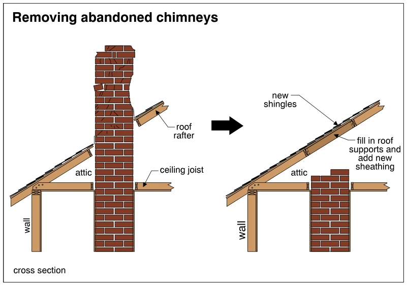 0969
0969Removing abandoned chimneys
· p. 165
Two cross sections show an abandoned masonry chimney before and after removal of its upper portion. The original brick chimney passes through the ceiling and sloped roof, and its exposed upper section appears cracked and irregular. An arrow leads to the completed condition, where the chimney terminates in the attic just above the ceiling joists. The former roof opening is filled with roof supports and new sheathing, and new shingles complete the continuous roof slope.
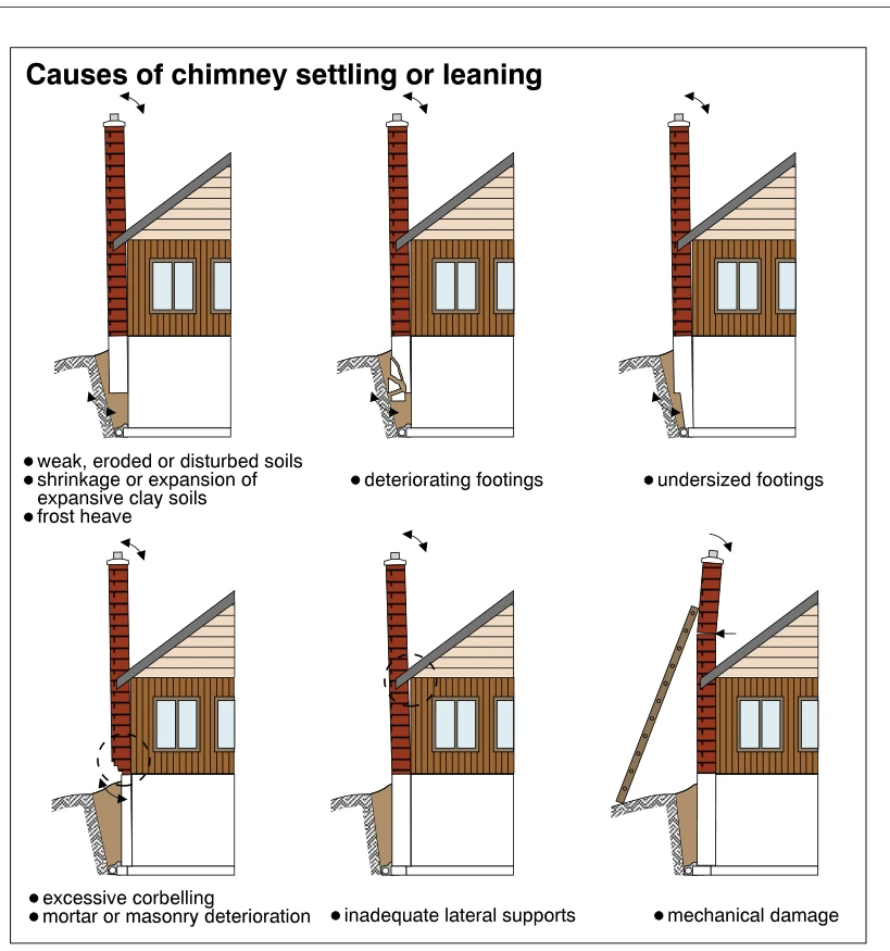 0970
0970Causes of chimney settling or leaning
· p. 166
Six schematic sections show exterior masonry chimneys beside a house, illustrating causes of chimney settlement or leaning. The upper row depicts unstable soil conditions, a deteriorating footing, and an undersized footing, with arrows indicating movement. The lower row illustrates excessive corbelling or masonry deterioration, inadequate lateral support at the house, and mechanical damage associated with a ladder bearing against the chimney. Cracks and displacement are shown at affected locations, and the final chimney is visibly leaning.
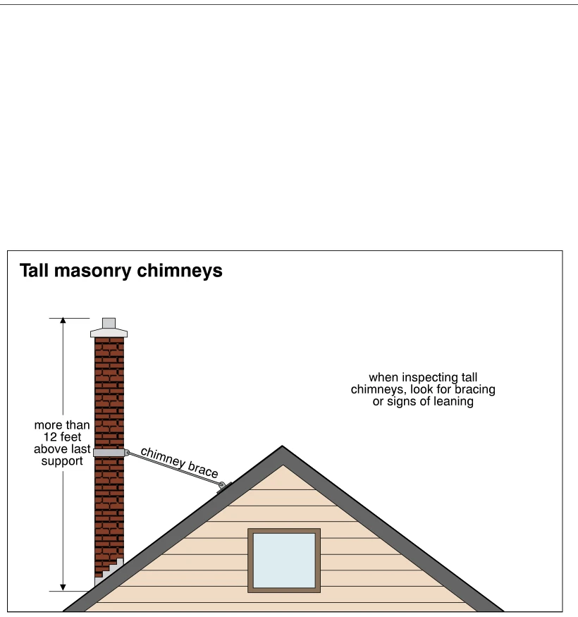 0971
0971Tall masonry chimneys
· p. 166
The illustration shows a tall brick masonry chimney beside a gable roof, extending well above the roof slope. A vertical dimension identifies a height of more than 12 feet above the last support. A diagonal chimney brace connects a band around the chimney to the sloped roof. A chimney crown and projecting flue termination are shown at the top, with flashing at the roof intersection. The annotation directs inspectors to look for bracing or signs of leaning when inspecting tall chimneys; no leaning is depicted.
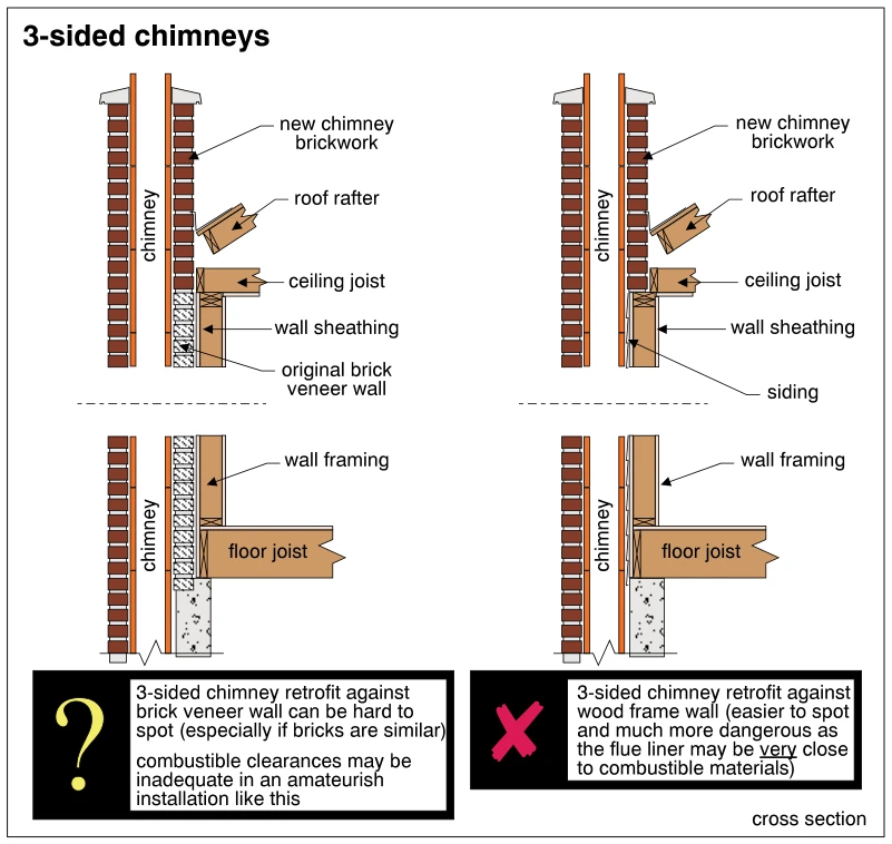 0972
09723-sided chimneys
· p. 166
Two cross sections depict three-sided masonry chimneys retrofitted against existing exterior walls, one with brick veneer and one with siding over wood framing. The sections show the chimney and flue liner beside wall sheathing, framing, floor joists, ceiling joists, and roof rafters. The left example retains the original brick veneer wall along the house side of the chimney and warns that matching brickwork can make the retrofit difficult to identify. Its annotation cautions that clearances to combustibles may be inadequate. The right example is marked with an X and warns that the flue liner may be very close to combustible materials in the wood-frame wall.
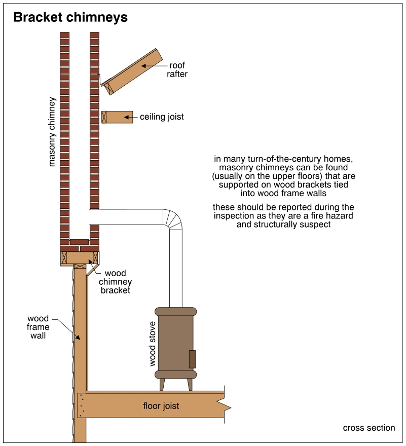 0973
0973Bracket chimneys
· p. 166
The cross section shows a masonry chimney supported on a wood bracket tied into a wood-frame wall rather than continuing down to a foundation. A wood stove connects to the chimney through a pipe with an elbow. Roof and ceiling framing are shown adjacent to the chimney, with a floor joist below the stove. The annotation identifies this arrangement as occurring in many turn-of-the-century homes, usually on upper floors, and warns that it is a fire hazard and structurally suspect that should be reported during inspection.
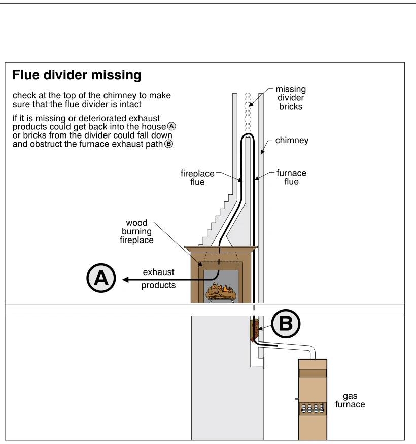 0974
0974Flue divider missing
· p. 167
A sectional drawing shows a masonry chimney containing adjacent flues serving a wood-burning fireplace and a gas furnace below. Divider bricks are missing near the top, allowing communication between the two flues. Path A shows furnace exhaust crossing into the fireplace flue and entering the house through the fireplace opening. Location B shows fallen divider bricks obstructing the furnace exhaust path near its connection to the chimney. The annotation advises checking the chimney top to confirm that the flue divider is intact.
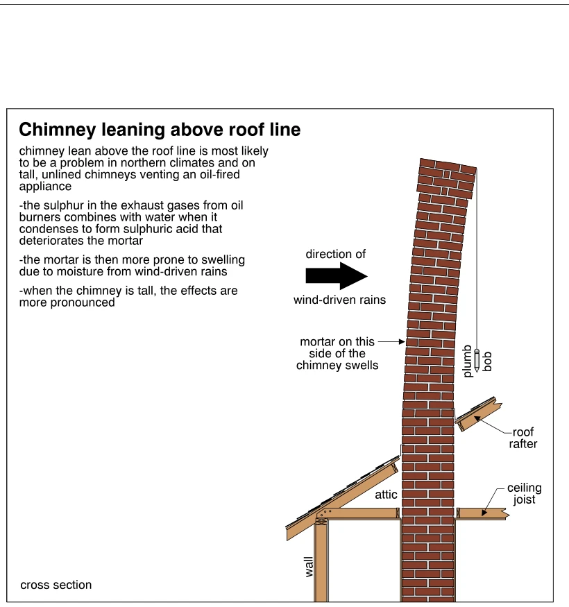 0975
0975Chimney leaning above roof line
· p. 167
A cross section shows a brick masonry chimney passing through an attic and sloped roof, with its exposed upper portion leaning to the right. A plumb bob beside the chimney provides a vertical reference for the lean. An arrow indicates wind-driven rain striking the left side, where an annotation identifies swelling mortar. The explanatory text links this condition to sulphuric acid deterioration of mortar in tall, unlined chimneys venting oil-fired appliances, followed by moisture-related swelling, particularly in northern climates. Roof rafters, ceiling joists, and an exterior wall establish the chimney’s relationship to the house framing.
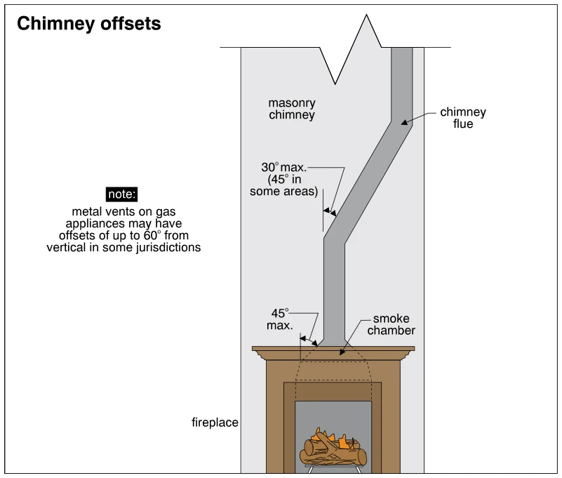 0976
0976Chimney offsets
· p. 167
The illustration shows a fireplace and smoke chamber beneath a masonry chimney with an offset flue. The flue rises vertically, shifts sideways through an inclined section, and resumes a vertical path. The offset is labeled 30° maximum from vertical, with 45° permitted in some areas. The sloping smoke chamber wall above the fireplace is labeled 45° maximum from vertical. A separate note states that metal vents on gas appliances may have offsets up to 60° from vertical in some jurisdictions.
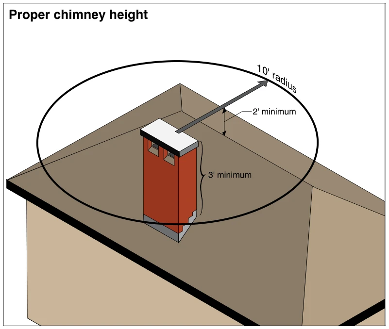 0977
0977Proper chimney height
· p. 167
The illustration shows a masonry chimney projecting through a sloped roof, with flashing at its base and a cap over the top. A vertical bracket identifies a minimum chimney height of 3 feet above the roof penetration. A circle and radial arrow mark a 10-foot radius around the chimney. Within this radius, the chimney top is shown at least 2 feet above the nearby roof high point, illustrating proper chimney termination height.
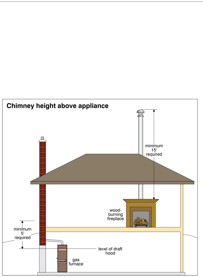 0978
0978Chimney height above appliance
· p. 168
The illustration shows a house section with a basement gas furnace connected by a vent connector to an exterior brick chimney, and a wood-burning fireplace connected to a vertical metal chimney through the roof. A horizontal reference line identifies the level of the furnace draft hood. Beside the masonry chimney, a vertical dimension indicates a minimum 5-foot requirement above that reference level. Beside the fireplace chimney, a vertical dimension from the top of the fireplace to the chimney termination indicates a minimum 15-foot requirement.
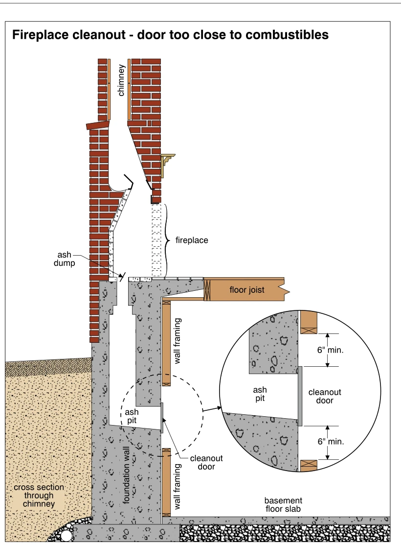 0979
0979Fireplace cleanout - door too close to combustibles
· p. 168
The illustration shows a cross section through a masonry fireplace and chimney, with an ash dump leading to an ash pit in the foundation below. A cleanout door provides access to the ash pit from the basement side of the foundation wall. Wood wall framing is shown beside the foundation, with a floor joist above and a basement floor slab below. An enlarged detail identifies a minimum 6-inch clearance between the cleanout door and combustible framing both above and below the door. The title identifies insufficient clearance to combustibles as the improper condition being addressed.
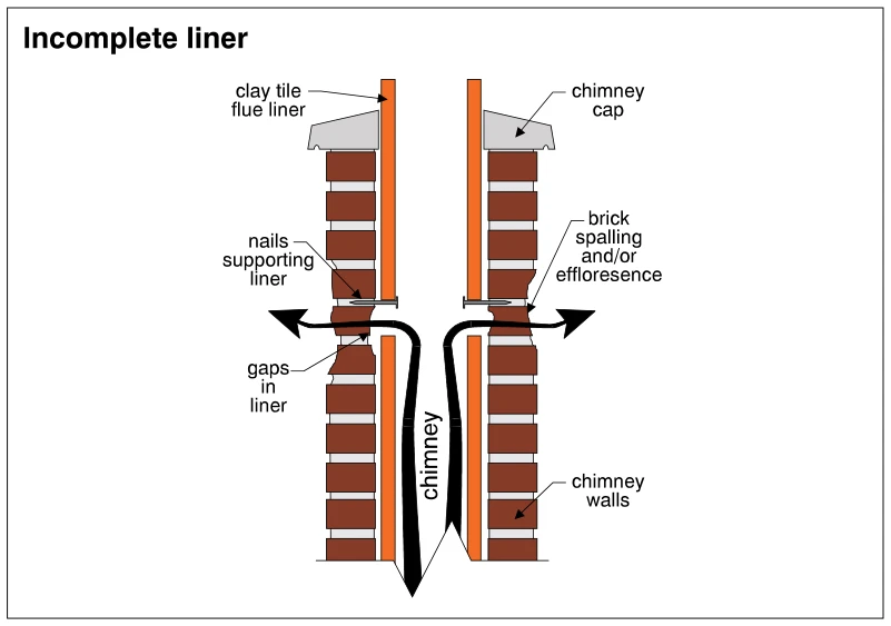 0980
0980Incomplete liner
· p. 168
A sectional drawing shows a brick masonry chimney with a clay tile flue liner and a sloped chimney cap. Gaps interrupt both sides of the liner near the upper portion of the chimney, where nails support the upper liner section. Heavy arrows show flow rising through the flue and escaping laterally through the liner gaps and chimney walls. The adjacent masonry is labeled as exhibiting brick spalling and/or efflorescence.
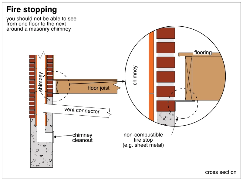 0981
0981Fire stopping
· p. 168
The illustration shows a cross section of a masonry chimney beside a wood-framed floor, with a vent connector and chimney cleanout below. An enlarged detail shows the clearance between the chimney masonry and the floor framing closed off at the floor level by a non-combustible fire stop. The fire stop spans the gap beneath the framing and turns down against the chimney. The annotation emphasizes that there should not be an open passage from one floor to the next around the chimney.
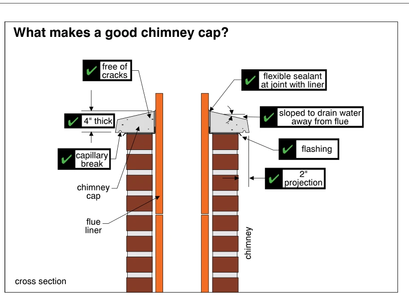 0982
0982What makes a good chimney cap?
· p. 169
A cross section of a masonry chimney shows a cap surrounding a flue liner that extends above the cap. Check-marked callouts identify a crack-free cap, 4 inches thick, with a surface sloped to drain water away from the flue. The cap projects 2 inches beyond the chimney masonry and has an underside capillary break near its outer edge. Flashing is shown beneath the cap, and flexible sealant is specified at the joint between the cap and liner.
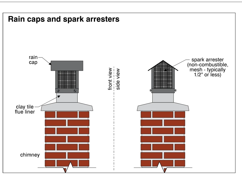 0983
0983Rain caps and spark arresters
· p. 169
The illustration shows front and side views of a brick masonry chimney fitted with a rain cap and spark arrester. A clay tile flue liner projects above the sloped chimney crown and supports the screened assembly. Non-combustible mesh surrounds the outlet beneath the rain cap, with the annotation specifying mesh typically 1/2 inch or less. The cap appears rectangular in front view and pitched in side view. No defects are depicted.
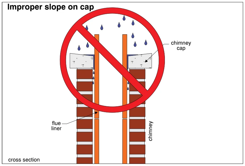 0984
0984Improper slope on cap
· p. 169
A cross section shows a brick masonry chimney with a flue liner extending above the chimney cap. The cap slopes inward toward the liner rather than outward toward the chimney edges. Rainwater is shown collecting at the liner and descending into the space between the liner and masonry. A large red prohibition symbol marks this cap configuration as improper.
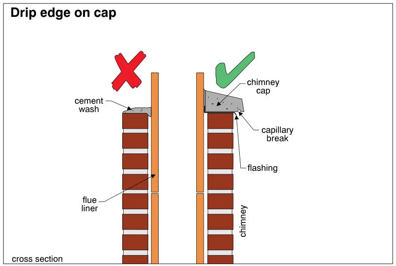 0985
0985Drip edge on cap
· p. 169
The illustration compares two masonry chimney-top details in cross section. On the left, a cement wash terminates at the brick face without an overhang or capillary break and is marked with a red X. On the right, a sloped chimney cap projects beyond the masonry and includes an underside capillary break at its outer edge, marked with a green check. Flashing is shown beneath the approved cap, and flue liners extend above both chimney-top finishes.
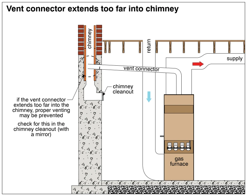 0987
0987Vent connector extends too far into chimney
· p. 169
The illustration shows a gas furnace connected to a masonry chimney by a vent connector, with return and supply ductwork alongside the furnace. A cutaway of the chimney shows the connector projecting too far into the lined flue, restricting the passage for exhaust gases. The annotation warns that this installation may prevent proper venting. A chimney cleanout below the connection is identified as an access point for checking the projection with a mirror.
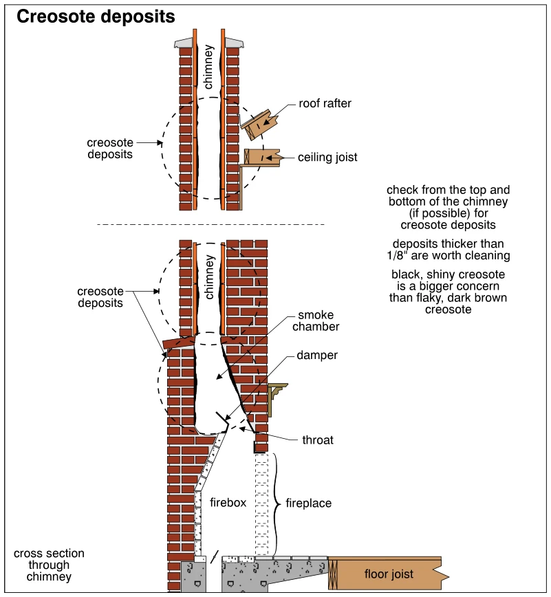 0986
0986Creosote deposits
· p. 169
The illustration shows a sectional view of a masonry fireplace and chimney, with a break separating the upper chimney from the fireplace assembly below. Dashed outlines and arrows identify creosote deposits along the chimney flue and around the smoke chamber above the firebox. The fireplace throat, damper, smoke chamber, and firebox are labeled, along with adjacent roof, ceiling, and floor framing. Annotations recommend checking from both ends of the chimney where possible and cleaning deposits thicker than 1/8 inch. Black, shiny creosote is identified as a greater concern than flaky, dark brown creosote.
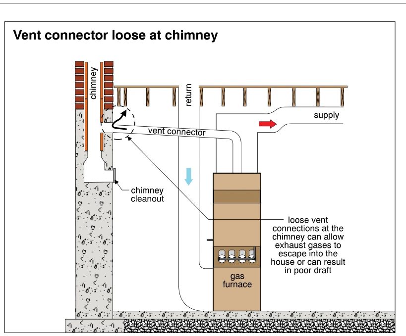 0988
0988Vent connector loose at chimney
· p. 170
The illustration shows a gas furnace connected to a masonry chimney by a metal vent connector. A circled area and an outward-pointing arrow highlight a loose connection where the vent connector enters the chimney. The annotation identifies exhaust gas escape into the house and poor draft as possible consequences. Supply and return ductwork are shown alongside the furnace, and a chimney cleanout is located below the vent entry.
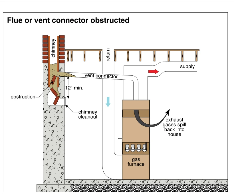 0989
0989Flue or vent connector obstructed
· p. 170
A sectional drawing shows a gas furnace connected to a masonry chimney by a metal vent connector. Debris obstructs the chimney flue at the connector entry and extends into the connector opening. A chimney cleanout is shown below the connection, with a vertical dimension labeled 12" min. A curved arrow indicates exhaust gases spilling from the furnace back into the house because of the obstruction. Supply and return ductwork and airflow arrows show the furnace's air-distribution arrangement.
 0990
0990Abandoned flue openings
· p. 170
The illustration shows a masonry chimney exposed inside a room, with an abandoned flue opening covered by a sheet metal plate. A red prohibition symbol marks this closure as improper. An enlarged detail shows the opening filled with masonry units and mortar, accompanied by a green check mark. The annotation explains that abandoned flue openings should be properly filled to prevent overheating or leakage of exhaust products.
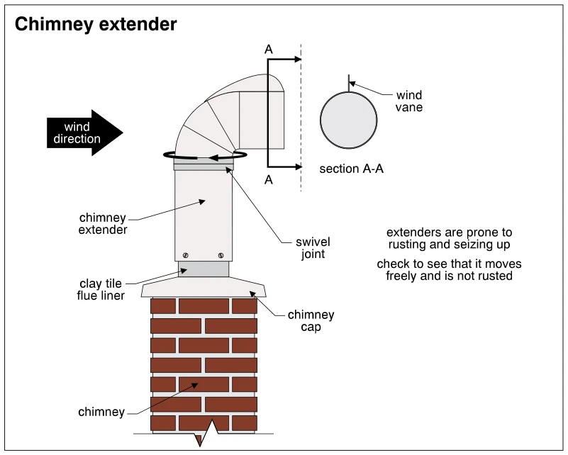 0991
0991Chimney extender
· p. 170
The illustration shows a swiveling chimney extender mounted above the projecting clay tile flue liner of a brick masonry chimney. The extender has a curved outlet, a swivel joint, and a wind vane shown in section A-A. Arrows indicate wind direction and rotation at the joint, with the outlet facing away from the incoming wind. The chimney cap covers the top of the masonry around the liner. Annotations warn that extenders are prone to rusting and seizing and instruct the inspector to check for free movement and rust.
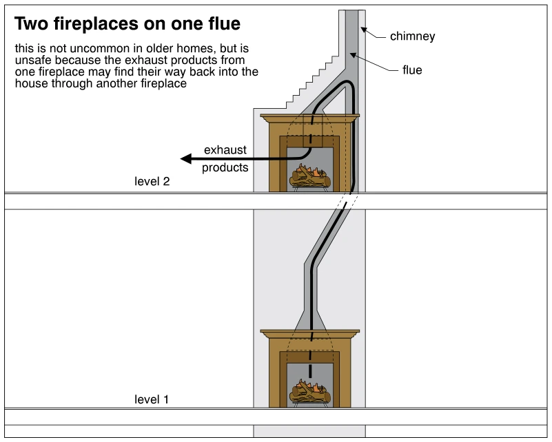 0992
0992Two fireplaces on one flue
· p. 170
The illustration shows two fireplaces on separate floor levels connected to a single flue within a chimney. The lower fireplace's passage rises and offsets toward the common vertical flue beside the upper fireplace. A heavy flow line and arrow show exhaust from the lower fireplace entering the upper fireplace and discharging into the room. The annotation identifies this shared-flue arrangement as an unsafe condition found in some older homes.
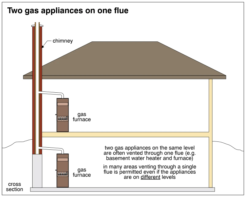 0993
0993Two gas appliances on one flue
· p. 170
A house cross section shows two gas furnaces on different levels connected to a single chimney flue. Each furnace has a separate vent connector entering the vertical flue at its respective level. The chimney extends above the roof along the side of the house. The annotations explain that two gas appliances on the same level often share a flue and that, in many areas, appliances on different levels may also share one. No specific defect is indicated.
Chimneys ·Metal Chimneys or Ventsp. 171
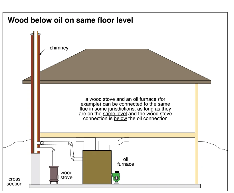 0994
0994Wood below oil on same floor level
· p. 171
A house cross section shows a wood stove and an oil furnace on the same basement floor connected to a common chimney flue. Separate vent connectors enter the chimney, with the wood stove connection below the oil furnace connection. The chimney extends up the side of the house and above the roof. The annotation states that this shared-flue arrangement is permitted in some jurisdictions when the appliances are on the same level and the wood connection is below the oil connection.
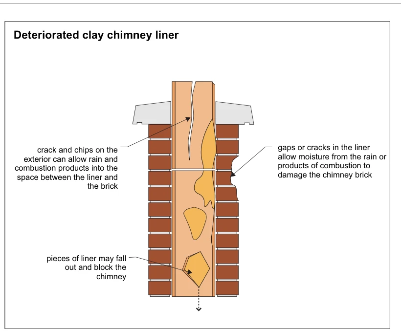 0994.5
Deteriorated clay chimney liner
· p. 171
A cutaway of a brick chimney shows a deteriorated clay flue liner extending above the chimney crown. The liner has a long crack, chipped areas, and missing sections. Callouts explain that these openings allow rain and combustion products into the space between the liner and the brick, where moisture can damage the masonry. A loose liner fragment and downward arrow illustrate how pieces can fall and obstruct the chimney.
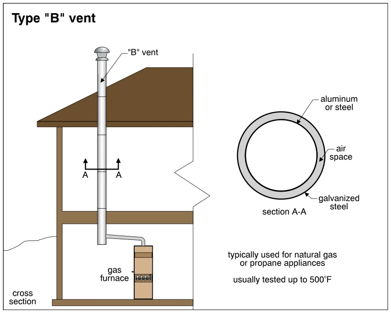 0995
0995Type "B" vent
· p. 171
A building cross section shows a gas furnace connected to a vertical Type B metal vent that extends through the building and roof to a capped termination. A separate section A-A depicts the vent's double-wall construction, with an aluminum or steel inner wall and a galvanized steel outer wall separated by an air space. The furnace connects to the vertical vent through an offset connector near its base. Annotations identify typical use with natural gas or propane appliances and state that the vent is usually tested up to 500°F. No specific installation defect is identified.
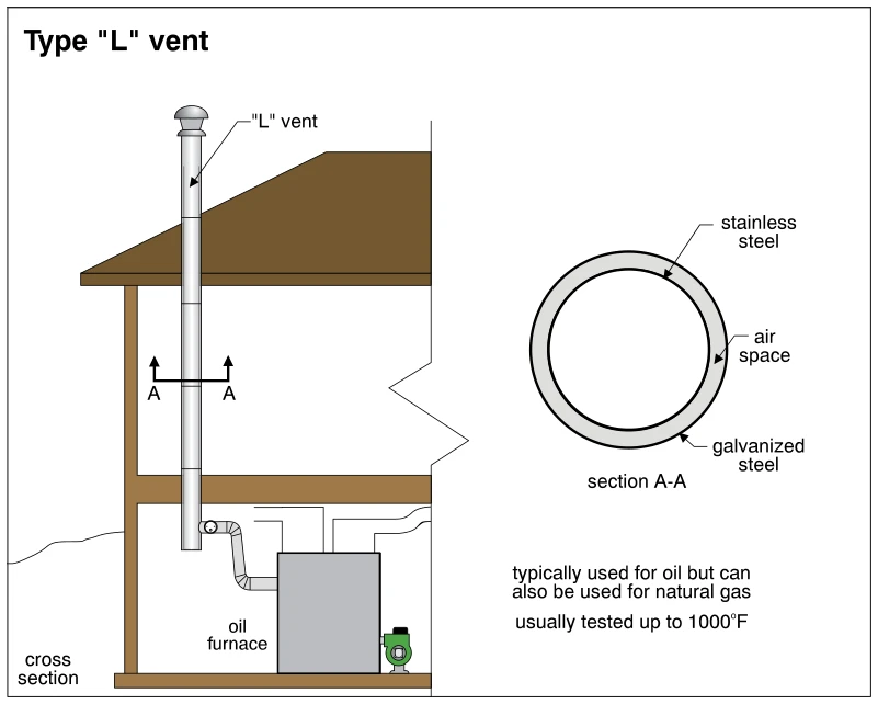 0996
0996Type "L" vent
· p. 171
A building cross section shows an oil furnace connected to a vertical Type L metal vent that extends through the roof and terminates with a cap. The furnace connects to the side of the vent through an offset connector near its base. An enlarged section A-A shows double-wall construction with a stainless steel inner wall, an intervening air space, and a galvanized steel outer wall. Notes state that this vent is typically used for oil but can also be used for natural gas, and is usually tested up to 1000°F. No defect or improper installation is explicitly depicted.
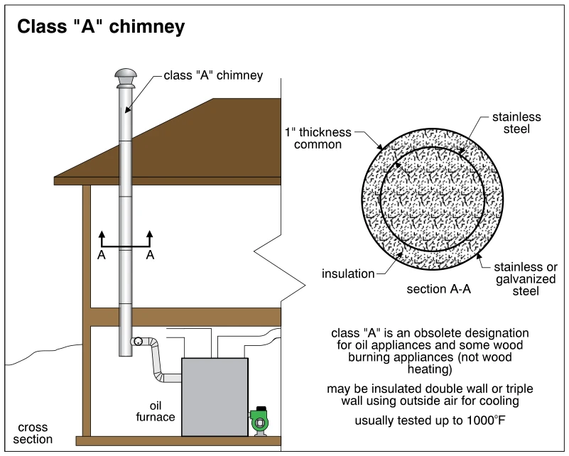 0997
0997Class "A" chimney
· p. 171
A building cross section shows an oil furnace connected by a metal vent connector to a vertical Class "A" chimney that passes through the floor and roof and terminates with a cap. Section A-A illustrates concentric chimney walls with insulation between a stainless steel inner wall and a stainless or galvanized steel outer wall. The insulation thickness is labeled as commonly 1 inch. Notes describe Class "A" as an obsolete designation for oil appliances and some wood-burning appliances, excluding wood heating, and mention insulated double-wall or air-cooled triple-wall construction. The drawing states that these chimneys are usually tested up to 1000°F; no specific defect is identified.
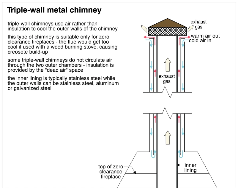 0998
0998Triple-wall metal chimney
· p. 171
The illustration shows a sectional view of a triple-wall metal chimney extending from the top of a zero-clearance fireplace to a capped, screened termination. Exhaust gases rise through the central flue, while cold air enters at the top and descends through the outer chamber before turning upward through the adjacent chamber and exiting as warm air. The text explains that air cools the outer chimney walls and that some triple-wall designs instead use noncirculating, dead-air spaces. It identifies stainless steel as the typical inner lining material and stainless steel, aluminum, or galvanized steel as possible outer-wall materials. An annotation warns that using this chimney type with a wood-burning stove would overcool the flue and cause creosote buildup.
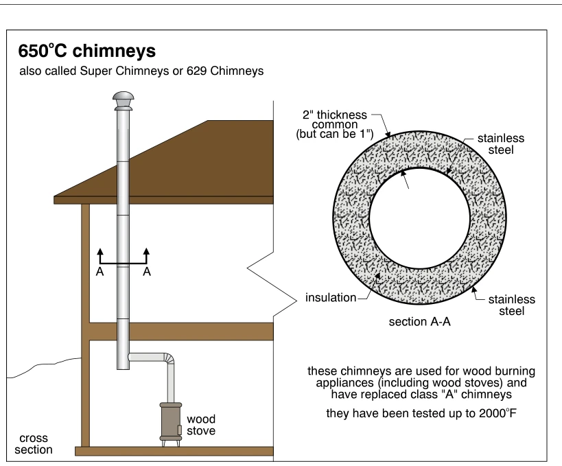 0999
0999650°C chimneys
· p. 172
A building cross section shows a wood stove connected by an elbowed connector pipe to a vertical metal chimney extending through the floor and roof and terminating with a cap. Section A-A shows the chimney's circular construction, with insulation between inner and outer stainless steel walls. The insulation thickness is labeled as commonly 2 inches, but potentially 1 inch. Notes identify these as 650°C chimneys, also called Super Chimneys or 629 Chimneys, used for wood-burning appliances and tested up to 2000°F. No specific installation defect is identified.
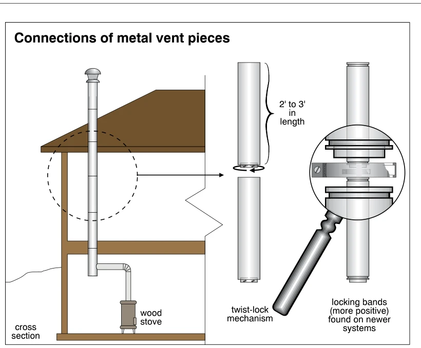 1000
1000Connections of metal vent pieces
· p. 172
A house cross section shows a wood stove connected by an elbowed connector to a vertical metal chimney extending above the roof and terminating in a cap. An enlarged view shows separate metal vent sections, labeled as 2 to 3 feet in length, with a rotational arrow illustrating a twist-lock connection. A second detail uses a magnifying-glass graphic to show a locking band securing the joint between sections. The annotation identifies locking bands as a more positive connection found on newer systems.
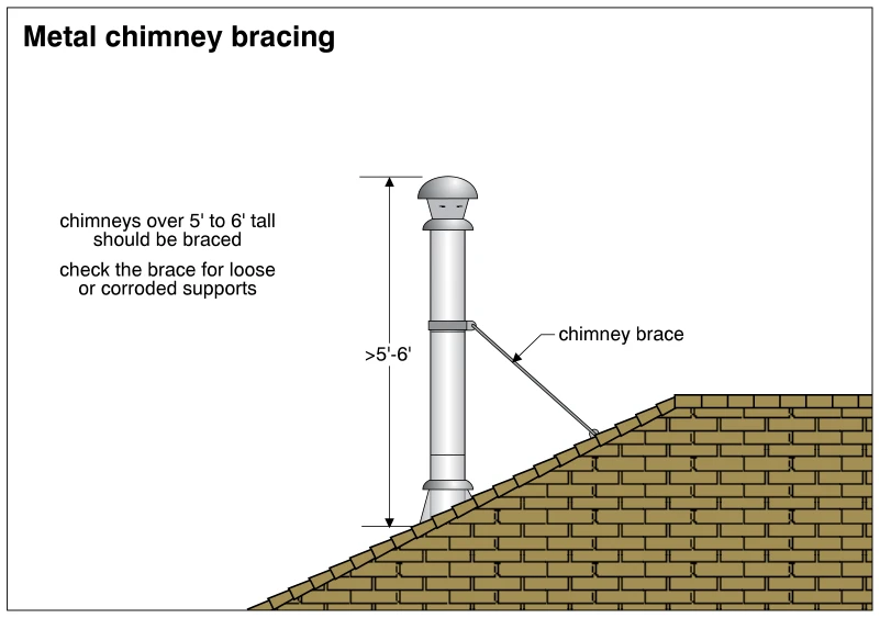 1001
1001Metal chimney bracing
· p. 172
The illustration shows a tall metal chimney projecting above a sloped, shingle-covered roof. A diagonal chimney brace connects a band around the chimney to the roof surface uphill of the penetration. A vertical dimension indicates a chimney height greater than 5 to 6 feet above the roof, and the annotation states that chimneys over this height should be braced. The drawing also directs inspectors to check the brace for loose or corroded supports; no such damage is depicted.
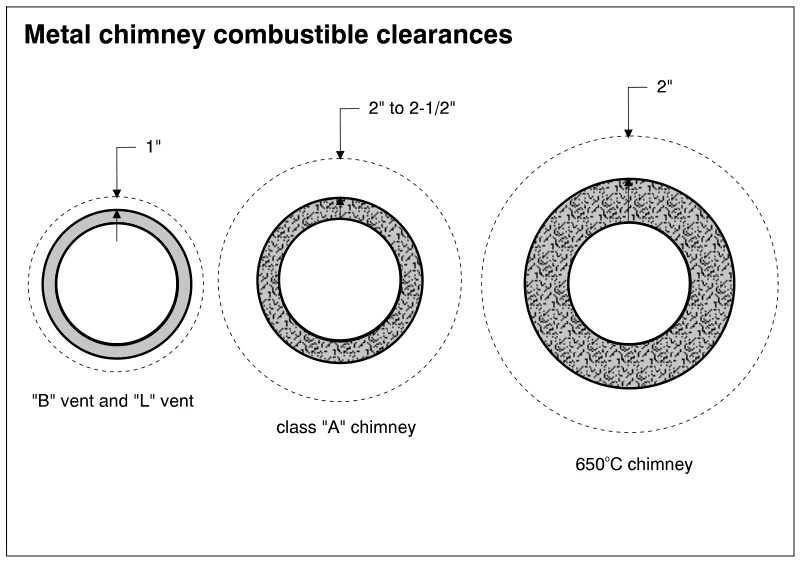 1002
1002Metal chimney combustible clearances
· p. 172
Three circular cross-sections illustrate combustible clearances around metal vents and chimneys. Dashed circles outside each assembly mark the clearance boundary, with arrows indicating the separation from the outer wall. The "B" and "L" vent assembly is shown with a 1-inch clearance, the class "A" chimney with a 2- to 2-1/2-inch clearance, and the 650°C chimney with a 2-inch clearance. The two chimney sections have stippled annular layers surrounding their central flue openings. No clearance violations are depicted.
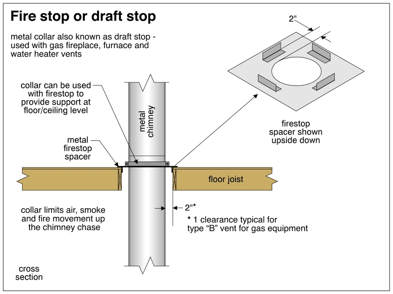 1003
1003Fire stop or draft stop
· p. 172
A cross section shows a metal chimney passing through a floor opening between floor joists, with a metal firestop spacer and collar at the floor/ceiling level. The collar closes the opening around the chimney to limit air, smoke, and fire movement up the chimney chase and can provide support in conjunction with the firestop. A dimension marks 2-inch clearance beside the chimney, with a note identifying a typical clearance of 1 for Type B gas-equipment vent. An inset shows the firestop spacer upside down as a square metal plate with a circular opening and four raised spacer tabs.
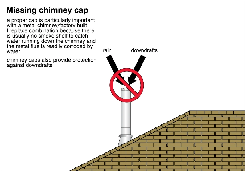 1004
1004Missing chimney cap
· p. 172
A metal chimney projects through a sloping shingle roof with flashing and a collar at its base. The chimney termination is open and lacks a cap, highlighted by a red prohibition symbol. Arrows labeled rain and downdrafts point into the open termination. The annotations explain that a cap is particularly important for a metal chimney serving a factory-built fireplace because there is usually no smoke shelf to catch incoming water and the metal flue is susceptible to corrosion.
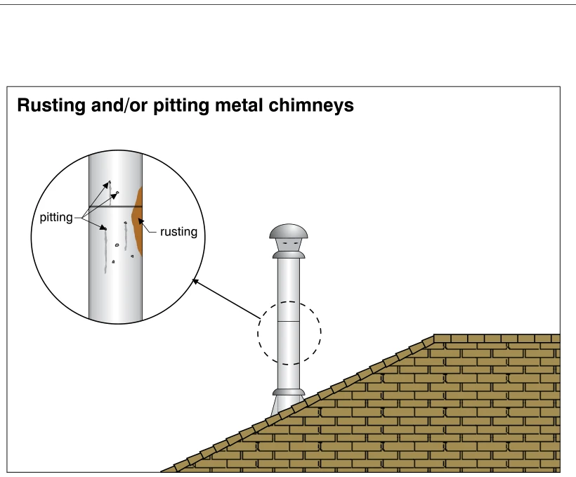 1005
1005Rusting and/or pitting metal chimneys
· p. 173
The illustration shows a capped metal chimney extending above a sloped, shingle-covered roof. The chimney has joined cylindrical sections and a collar at its roof penetration. A circular enlargement of the chimney wall highlights small surface pits and a larger rusted patch. These conditions depict corrosion and deterioration of the metal chimney.
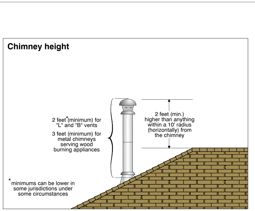 1006
1006Chimney height
· p. 173
The illustration shows a capped metal chimney or vent extending through a sloped, shingled roof near the ridge. A bracket indicates minimum heights above the roof of 2 feet for "L" and "B" vents and 3 feet for metal chimneys serving wood-burning appliances. A vertical dimension specifies that the termination must be at least 2 feet higher than anything within a horizontal radius of 10 feet. A footnote states that minimums can be lower in some jurisdictions under some circumstances.
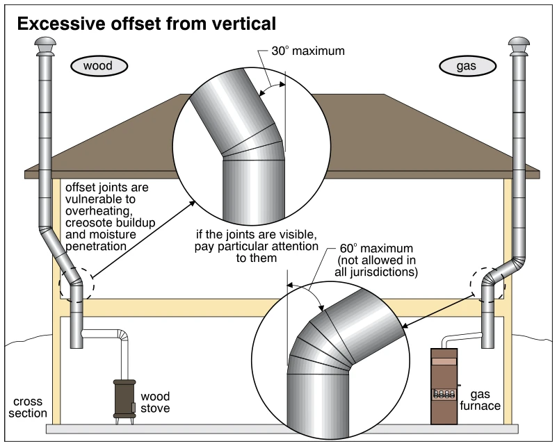 1007
1007Excessive offset from vertical
· p. 173
A house cross section compares an exterior metal chimney serving a wood stove with an exterior metal vent serving a gas furnace. Both vertical runs have angled offsets near the floor framing and extend above the roof with caps. Enlarged details show the offset joints and indicate maximum angles from vertical of 30° for wood and 60° for gas, with the gas allowance noted as not permitted in all jurisdictions. The illustration warns that offset joints are vulnerable to overheating, creosote buildup, and moisture penetration, and directs inspectors to pay particular attention to visible joints.
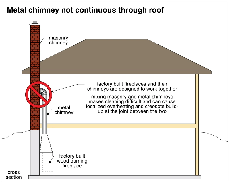 1008
1008Metal chimney not continuous through roof
· p. 173
A house cross section shows a factory-built wood-burning fireplace connected to a vertical metal chimney beside a masonry chimney. The metal chimney turns into the masonry chimney below the roof rather than continuing through the roof independently. A red prohibition symbol marks the junction as improper. The annotations explain that factory-built fireplaces and their chimneys are designed to work together, and that mixing masonry and metal chimneys makes cleaning difficult and can cause localized overheating and creosote buildup at the joint.
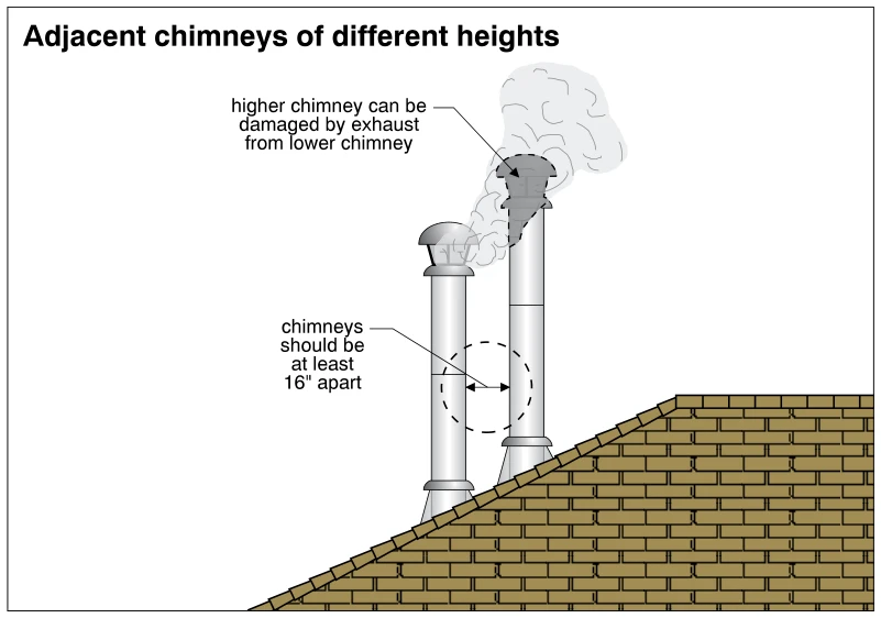 1009
1009Adjacent chimneys of different heights
· p. 173
Two capped metal chimneys of different heights extend through a sloped, shingled roof. Exhaust from the lower chimney drifts toward and around the upper portion of the taller chimney. An annotation warns that this exhaust can damage the higher chimney. A horizontal dimension arrow between the chimney walls indicates that the chimneys should be at least 16 inches apart.
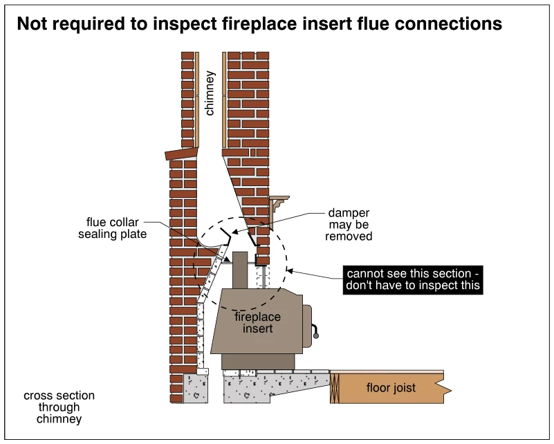 1010
1010Not required to inspect fireplace insert flue connections
· p. 173
A cross section through a masonry chimney shows a fireplace insert projecting from the fireplace opening, with a floor joist beside the hearth support. The insert's flue outlet extends upward toward the fireplace throat, where a flue collar sealing plate is identified. An annotation indicates that the damper may be removed. A dashed circle highlights the concealed flue connection area, with a note stating that this unseen section does not have to be inspected.
Wood Heating Systems ·Furnaces and Boilersp. 174
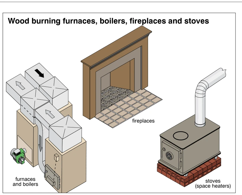 1011
1011Wood burning furnaces, boilers, fireplaces and stoves
· p. 174
The illustration presents examples of wood-burning heating appliances: furnaces and boilers, an open fireplace, and a freestanding space-heating stove. The equipment at left has rectangular overhead ductwork with arrows indicating airflow, front access doors, and a side-mounted mechanical unit. The central fireplace has a mantel and surround, an open firebox, and a tiled hearth extending in front. The stove at right has a front loading door with a circular air control, a circular top plate, and a vertical flue connector that bends toward the upper right. It rests on a raised brick base; no specific defect or installation comparison is identified.
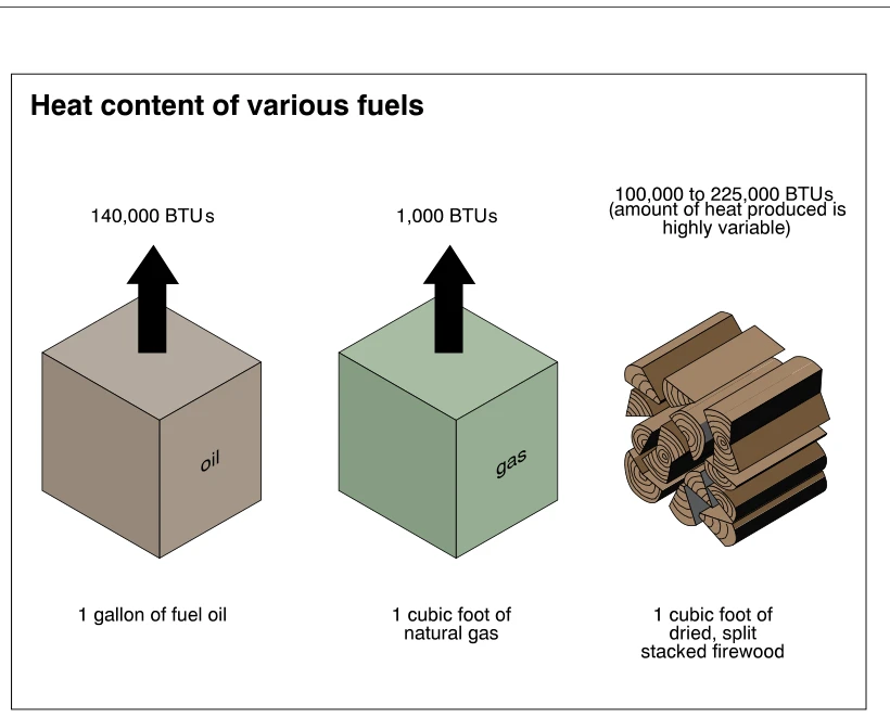 1012
1012Heat content of various fuels
· p. 174
The illustration presents the heat content of measured quantities of three heating fuels. A block labeled oil has an upward arrow indicating 140,000 BTUs for 1 gallon of fuel oil. A block labeled gas has an upward arrow indicating 1,000 BTUs for 1 cubic foot of natural gas. A stack of split logs represents 1 cubic foot of dried, split stacked firewood, with a heat content of 100,000 to 225,000 BTUs and a note that the amount of heat produced is highly variable. No heating equipment or installation defects are shown.
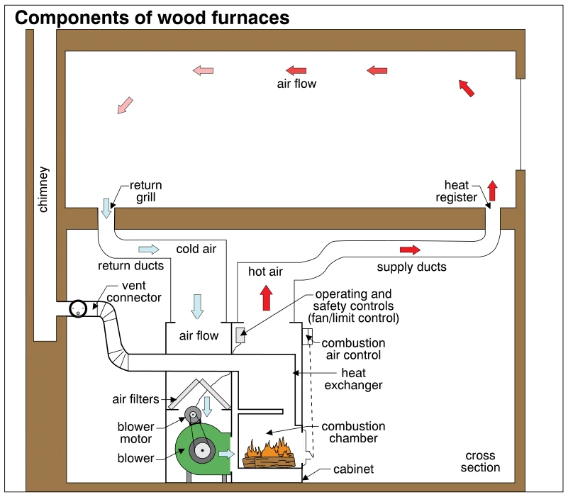 1013
1013Components of wood furnaces
· p. 174
A cross section shows a wood-burning forced-air furnace below a room, connected to supply and return ducts. Cool room air enters the return grille, travels down the return duct through air filters, and is moved by a motor-driven blower through the furnace. Air heated by the heat exchanger rises into the supply ducts and enters the room through a heat register, with arrows tracing the circulation path. Burning logs are shown in the combustion chamber, and a vent connector leads from the furnace to the chimney. The drawing also identifies the cabinet, combustion air control, and operating and safety controls, including the fan/limit control.
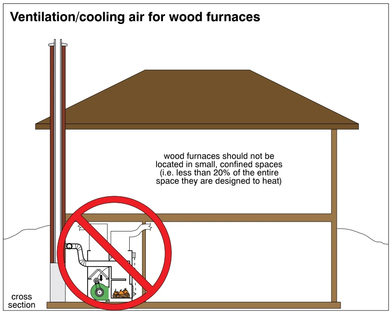 1014
1014Ventilation/cooling air for wood furnaces
· p. 174
A house cross section shows a wood furnace enclosed in a small basement compartment. The furnace is depicted with a burning fire, a blower, overhead duct connections, and a flue connection to a vertical chimney extending above the roof. A red prohibition symbol overlays the furnace enclosure to indicate improper placement. The annotation warns against locating wood furnaces in confined spaces smaller than 20% of the total space they are designed to heat, emphasizing the need for ventilation and cooling air.
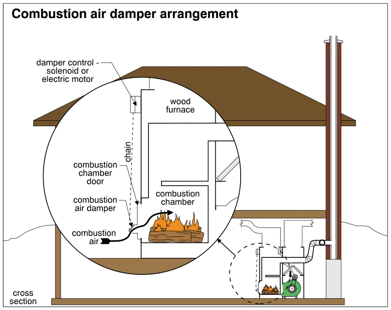 1015
1015Combustion air damper arrangement
· p. 174
A house cross section shows a wood furnace connected to overhead ductwork and a tall chimney by a vent connector. An enlarged detail shows burning logs in the combustion chamber and combustion air entering through a damper near the bottom of the chamber door. A chain connects the damper to a control labeled as a solenoid or electric motor. Arrows indicate the incoming combustion-air path toward the fire. The illustration explains the damper arrangement without identifying a defect.
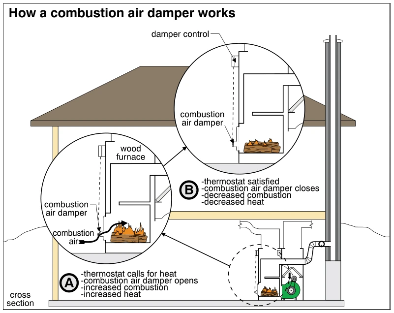 1016
1016How a combustion air damper works
· p. 174
A house cross section shows a basement wood furnace connected to ductwork and a vertical chimney. Two enlarged views illustrate how a controlled combustion air damper regulates the wood fire. In condition A, the thermostat calls for heat, the damper opens, and incoming combustion air increases combustion and heat output. In condition B, the thermostat is satisfied, the damper closes, and combustion and heat output decrease. A dashed linkage connects the damper control to the combustion air damper.
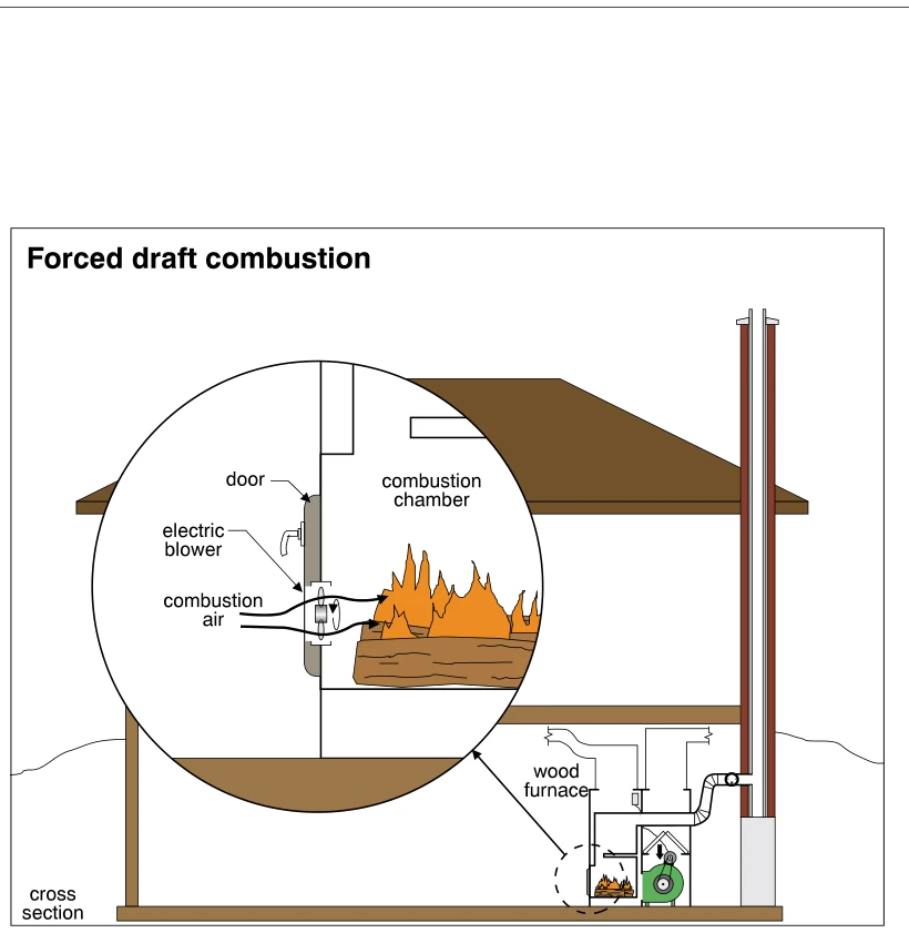 1017
1017Forced draft combustion
· p. 175
A house cross section shows a wood furnace at the lowest level connected by a flue pipe to a vertical chimney extending above the roof. An enlarged detail shows burning logs inside the furnace combustion chamber and an electric blower mounted at the door. Arrows indicate combustion air being forced through the door into the fire. The main furnace drawing also shows duct connections and a separate circulation blower. The illustration explains forced-draft combustion rather than depicting a defect.
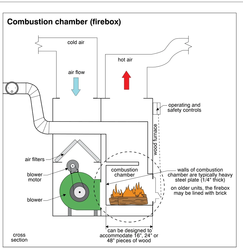 1018
1018Combustion chamber (firebox)
· p. 175
A cross section shows a wood-fired forced-air furnace with burning logs in its combustion chamber. Cold return air enters above the air filters and belt-driven blower, while heated air exits through the upper hot-air duct. A flue passage leads from above the firebox to a pipe at the left, and operating and safety controls are shown on the furnace side. Annotations identify typical firebox walls as heavy steel plate, 1/4 inch thick, and note that older units may have brick linings. A dimension annotation indicates that fireboxes can be designed to accommodate 16-, 24-, or 48-inch pieces of wood.
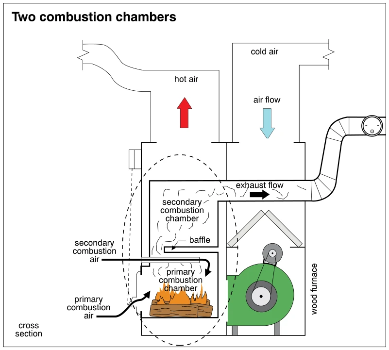 1019
1019Two combustion chambers
· p. 175
A cross-section of a wood furnace shows a lower primary combustion chamber containing burning logs and an upper secondary combustion chamber. Separate arrows indicate primary combustion air entering the firebox and secondary combustion air entering above the fuel. A baffle separates portions of the combustion path, with exhaust flowing through the upper chamber and into a flue connector on the right. A belt-driven blower circulates cold return air through the furnace, while heated supply air exits through the duct on the upper left. The illustration explains the two-chamber arrangement without depicting a defect.
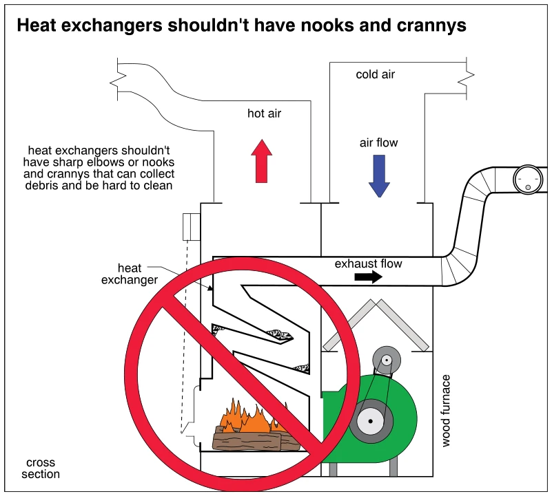 1020
1020Heat exchangers shouldn't have nooks and crannys
· p. 175
The illustration shows a cross section of a wood furnace with burning logs, a heat exchanger, a belt-driven blower, and supply and return air ducts. Arrows show cold air entering from above, heated air leaving through the opposite duct, and exhaust traveling to the flue connector on the right. The heat exchanger has a zigzag passage with sharp turns and pockets where debris is shown accumulating. A red prohibition symbol emphasizes that these debris-trapping, difficult-to-clean heat exchanger configurations are improper.
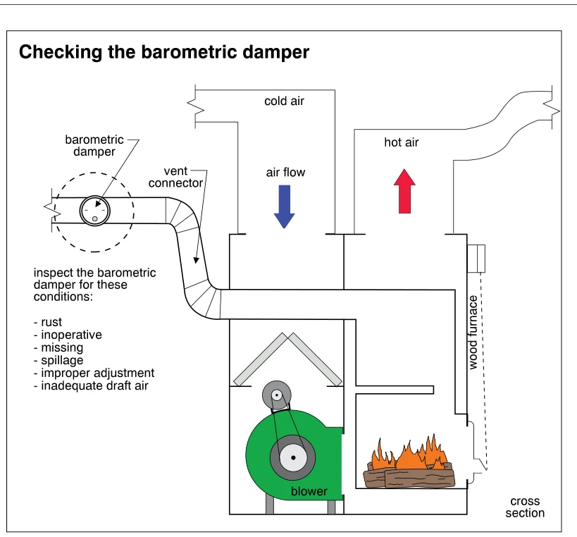 1021
1021Checking the barometric damper
· p. 176
The illustration shows a cross section of a wood-fired forced-air furnace with a blower, burning logs in the firebox, and cold-air and hot-air ducts. Arrows indicate cold air moving downward toward the blower and heated air rising into the supply duct. A vent connector runs from the furnace to the left, with a barometric damper installed in its horizontal section. A dashed circle highlights the damper, and an inspection checklist identifies conditions to check rather than showing a specific failure.
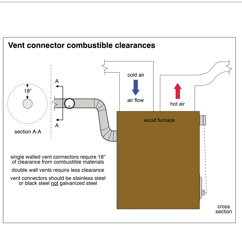 1022
1022Vent connector combustible clearances
· p. 176
The illustration shows a wood furnace in cross section, with cold return air entering from above and hot supply air leaving through an adjacent duct. A vent connector exits the side of the furnace and rises through elbows to a horizontal run. Section A-A shows an 18-inch clearance from the outer surface of the single-wall connector to surrounding combustible materials. Notes state that double-wall vents require less clearance and that vent connectors should be stainless steel or black steel, not galvanized steel.
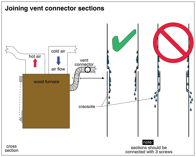 1023
1023Joining vent connector sections
· p. 176
The illustration shows a wood furnace with hot-air and cold-air ducts and a vent connector, alongside enlarged cross sections comparing two vent connector joints. The correct joint, marked with a green check, has the upper section inserted inside the lower section so descending creosote stays within the connector. The incorrect joint reverses the overlap, allowing creosote to escape at the joint and run down the outside. A note specifies that sections should be connected with three screws.
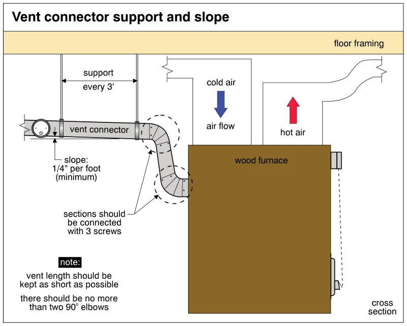 1024
1024Vent connector support and slope
· p. 176
The cross-section shows a wood furnace with cold-air and hot-air ducts above it and a vent connector leaving its side through two elbows. The connector slopes upward away from the furnace at a labeled minimum of 1/4 inch per foot and is suspended from floor framing with supports every 3 feet. Dashed circles highlight connector joints, with an annotation requiring three screws at section connections. Notes specify keeping the vent length as short as possible and using no more than two 90-degree elbows.
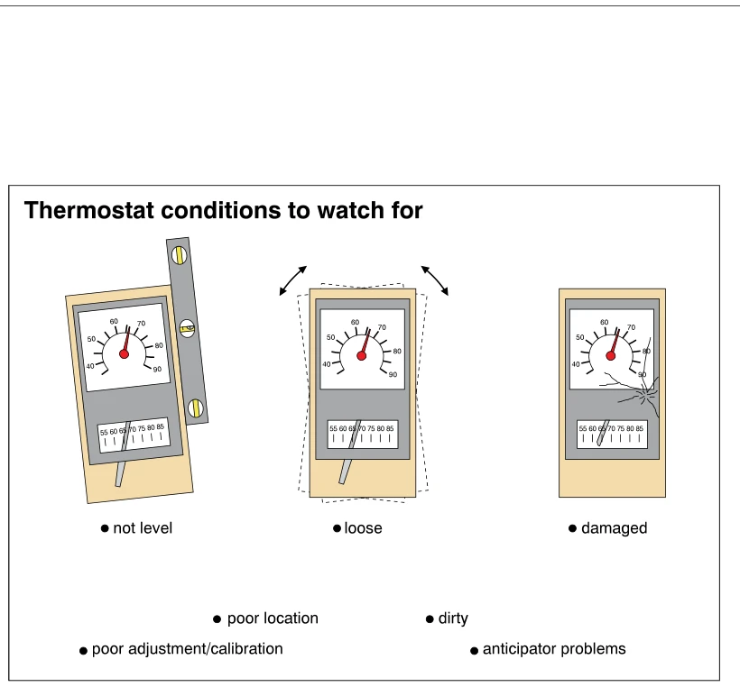 1025
1025Thermostat conditions to watch for
· p. 177
The illustration shows three wall thermostats demonstrating conditions to watch for during a heating-system inspection. The left thermostat is tilted, with a spirit level alongside it to illustrate an out-of-level installation. The center thermostat has dashed outlines and movement arrows indicating loose mounting. The right thermostat has a visibly cracked face indicating damage. Additional annotations identify poor location, dirt, poor adjustment or calibration, and anticipator problems as inspection concerns.
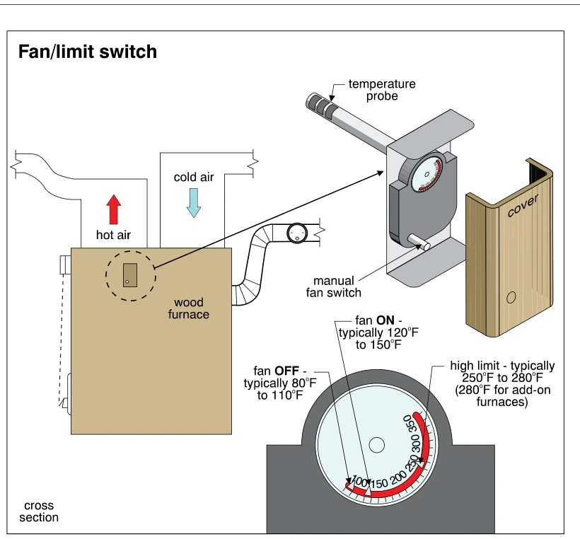 1026
1026Fan/limit switch
· p. 177
The illustration shows a wood furnace with cold-air and hot-air ducts and identifies the location of its fan/limit switch. An enlarged view shows the switch with its cover removed, exposing the temperature dial, projecting temperature probe, and manual fan switch. A detailed dial view identifies typical fan-on settings of 120°F to 150°F and fan-off settings of 80°F to 110°F. The high-limit setting is labeled as typically 250°F to 280°F, with 280°F specified for add-on furnaces. Airflow arrows distinguish the incoming cold air from the outgoing hot air.
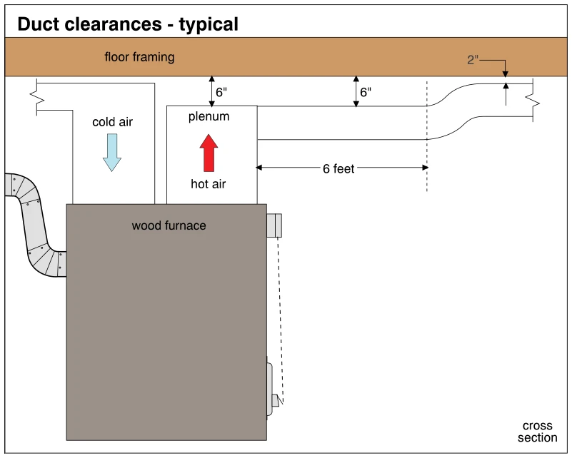 1027
1027Duct clearances - typical
· p. 177
The cross section shows a wood furnace with a cold-air return entering at the top and a hot-air plenum feeding a horizontal supply duct beneath floor framing. Arrows indicate downward cold-air flow and upward hot-air flow. The plenum and the first 6 feet of supply duct are shown with 6-inch clearance below the framing. Beyond that distance, the supply duct offsets upward, with a 2-inch clearance indicated. A segmented flue connector is also visible at the side of the furnace.
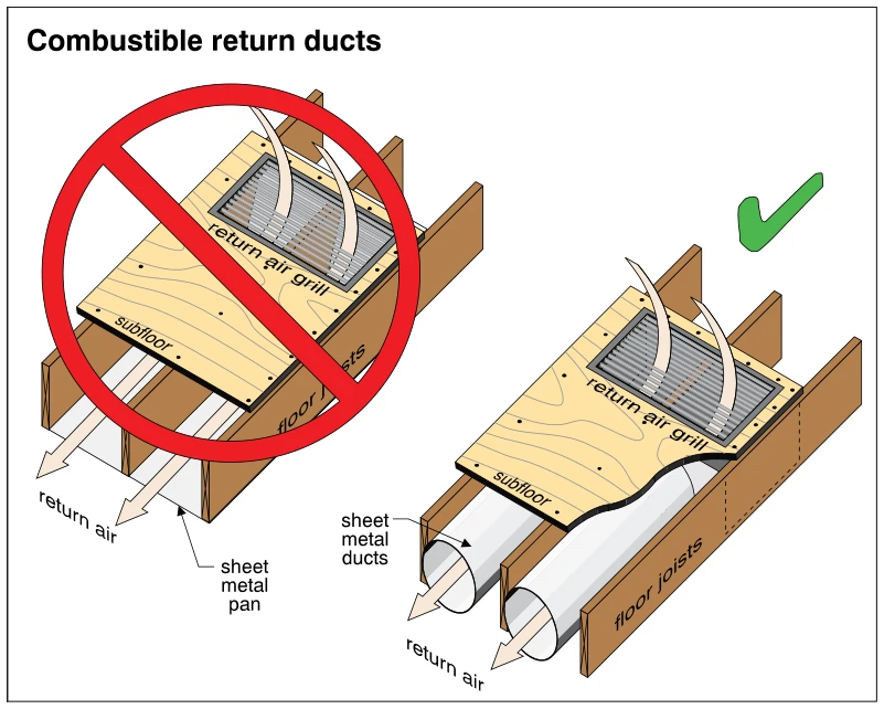 1028
1028Combustible return ducts
· p. 177
The illustration compares two floor-level return-air arrangements in the context of wood furnaces. On the left, a red prohibition symbol marks a return-air pathway formed by wood floor joists, wood subfloor, and a sheet metal pan beneath the joists. This arrangement exposes combustible framing and subfloor to the return-air passage. On the right, a green check marks separate sheet metal ducts installed between the floor joists beneath the return-air grille. Arrows show return air entering through each grille and traveling through the passages below.
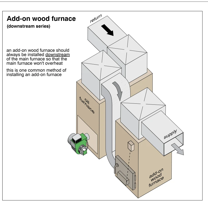 1029
1029Add-on wood furnace (downstream series)
· p. 178
The illustration shows an oil furnace and an add-on wood furnace connected in a downstream series arrangement. Return air enters the main oil furnace, and a connecting duct carries its discharge air downward into the add-on wood furnace. Air then leaves the wood furnace through its upper plenum and supply duct, as indicated by the airflow arrows. The annotation specifies that the wood furnace should be downstream of the main furnace to prevent the main furnace from overheating. An oil burner is shown on the main furnace, while the wood furnace has a front loading door and a small control linked to the door area.
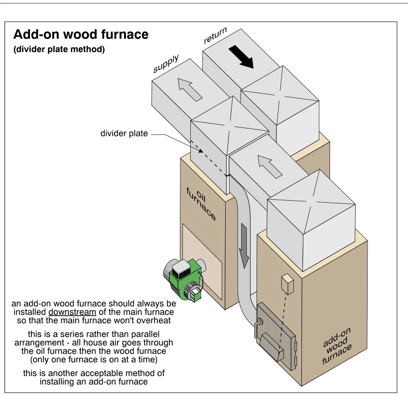 1030
1030Add-on wood furnace (divider plate method)
· p. 178
The illustration shows an oil furnace connected in series with an add-on wood furnace using the divider plate method. Return air enters above the oil furnace, and arrows show air routed downward through connecting ductwork toward the wood furnace. Air leaving the top of the wood furnace travels through an upper connecting duct to the house supply duct. A divider plate separates the airflow paths above the oil furnace. The annotations identify this as an acceptable installation, with the wood furnace downstream to prevent overheating of the main furnace and only one furnace operating at a time.
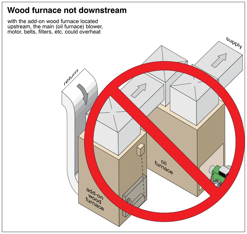 1031
1031Wood furnace not downstream
· p. 178
The illustration shows an add-on wood furnace connected in series upstream of an oil furnace in a forced-air heating system. Return air enters the wood furnace, and arrows indicate airflow through connecting ductwork toward the oil furnace and then into the supply duct. A large red prohibition symbol marks this arrangement as incorrect. The annotation warns that locating the wood furnace upstream could overheat the main oil furnace's blower, motor, belts, filters, and other components.
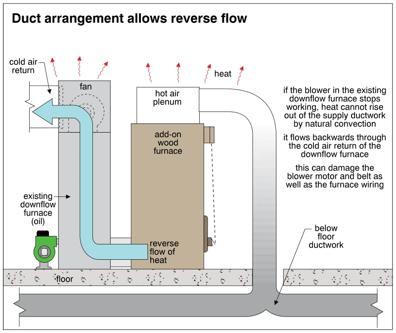 1032
1032Duct arrangement allows reverse flow
· p. 178
The diagram shows an add-on wood furnace connected to an existing oil-fired downflow furnace and below-floor supply ductwork. The wood furnace's hot air plenum connects to a duct that descends through the floor to the supply trunk. A large arrow shows heat flowing backward from the wood furnace through the downflow furnace and out its cold air return. The annotations explain that if the existing furnace blower stops, heat cannot rise out of the supply ductwork by natural convection, and this reverse flow can damage the blower motor, belt, and furnace wiring.
Wood Heating Systems ·Wood Stoves (Space Heaters)p. 179
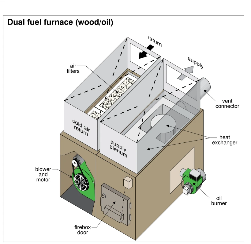 1033
1033Dual fuel furnace (wood/oil)
· p. 179
This cutaway illustration shows a dual-fuel wood/oil forced-air furnace. The cold-air return contains air filters and connects to a compartment containing the blower and motor. The adjacent supply plenum sits above the heat exchanger, with arrows indicating return air entering and supply air leaving the furnace. A firebox door is mounted on the front, an oil burner projects from the side, and a vent connector extends from the upper rear of the unit. No defects or improper installation practices are indicated.
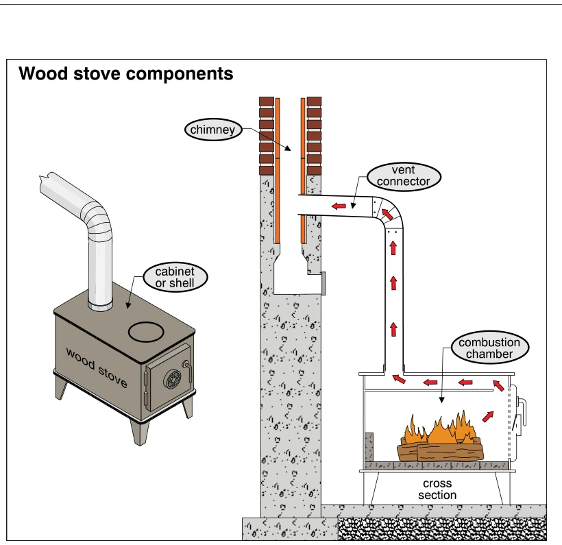 1034
1034Wood stove components
· p. 179
The illustration pairs an exterior view of a freestanding wood stove with a cross section of a stove connected to a masonry chimney. The exterior view shows the cabinet or shell, loading door, legs, and stovepipe. The cross section shows burning logs in the combustion chamber and a lined base. Red arrows trace combustion gases around an internal baffle, up the vent connector, and through an elbow into the chimney. The chimney is shown in section with a flue liner and a lower access opening.
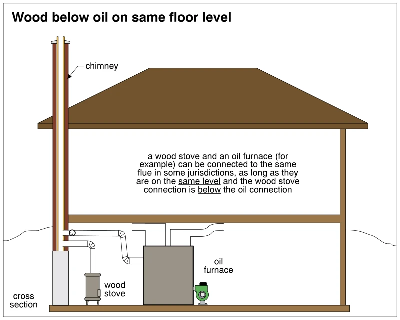 1035
1035Wood below oil on same floor level
· p. 179
A house cross section shows a wood stove and an oil furnace located on the same lower floor and connected to a common chimney flue. Separate vent connectors enter the chimney, with the wood stove connection below the oil furnace connection. The chimney extends above the roof, and ductwork rises from the furnace. The annotation identifies this shared-flue arrangement as permitted in some jurisdictions, provided the appliances are on the same level and the wood connection is below the oil connection.
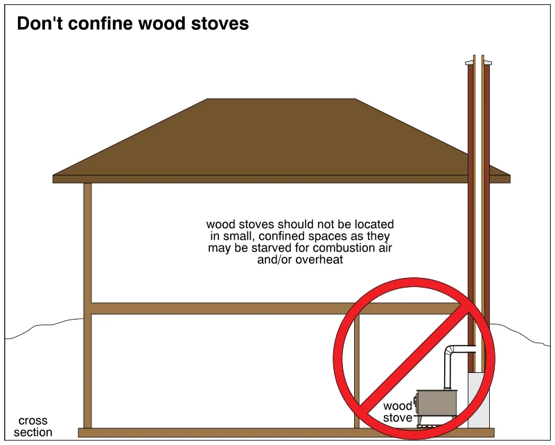 1036
1036Don't confine wood stoves
· p. 179
A house cross section shows a wood stove installed in a small, partitioned space on the lower level. A connector pipe rises from the stove and turns toward a vertical chimney extending above the roof. A large red prohibition symbol overlays the stove and its confined enclosure. The annotation warns that wood stoves in small, confined spaces may be starved for combustion air and/or overheat.
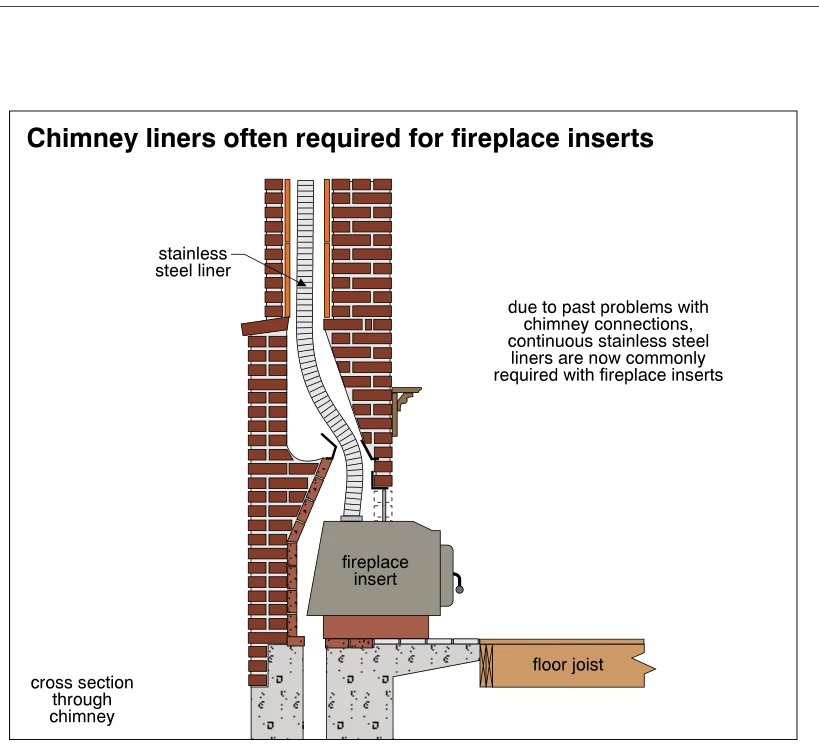 1037
1037Chimney liners often required for fireplace inserts
· p. 180
The illustration shows a cross section through a masonry fireplace and chimney with a fireplace insert installed in the firebox. A continuous stainless steel liner connects to the top of the insert, bends through the fireplace throat and smoke chamber, and extends upward within the chimney flue. Brick masonry surrounds the assembly, with a concrete support below the hearth and a wood floor joist alongside it. The annotation explains that continuous stainless steel liners are now commonly required for fireplace inserts because of past problems with chimney connections.
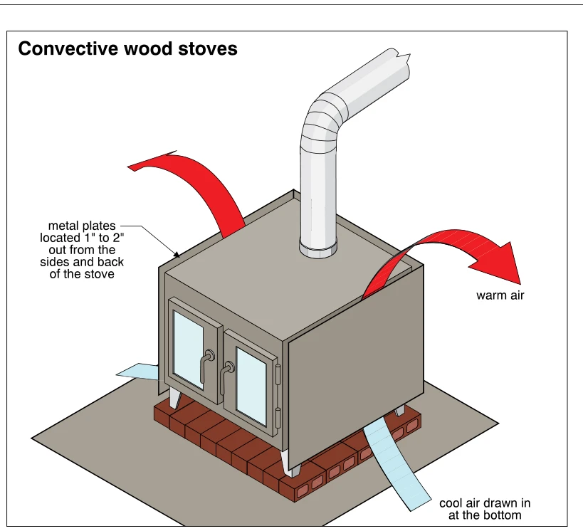 1038
1038Convective wood stoves
· p. 180
The illustration shows a freestanding wood stove with metal plates spaced 1 to 2 inches from its sides and back to form convection passages. Blue arrows indicate cool room air entering at the bottom, and red arrows show warmed air exiting at the top. The stove has two glazed front doors and a top-mounted flue connector with an elbow. It stands on short legs on a brick hearth over a larger floor pad. The drawing explains convective heat distribution rather than depicting an installation defect.
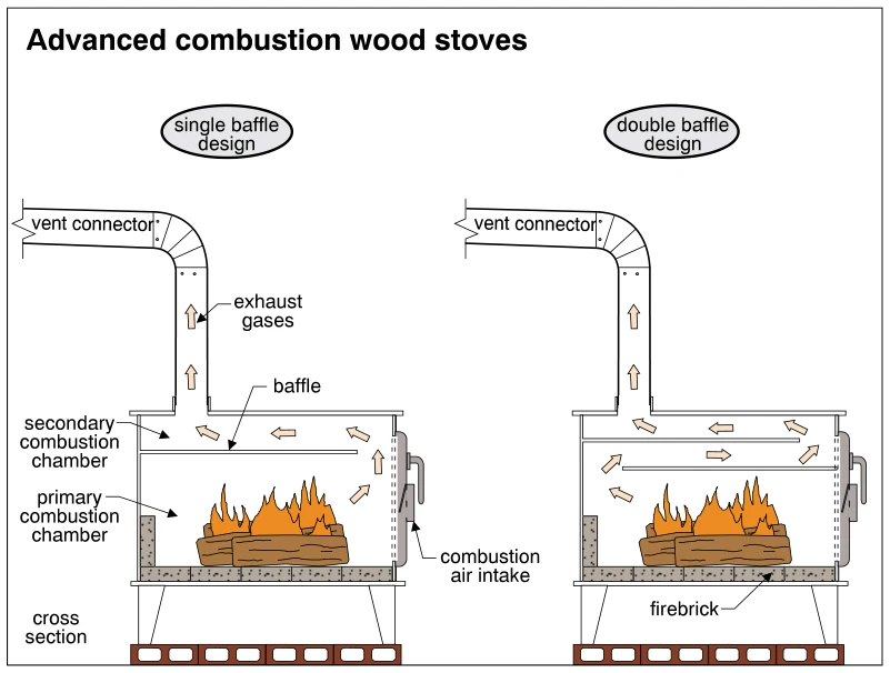 1039
1039Advanced combustion wood stoves
· p. 180
Two cross-sectional diagrams show advanced combustion wood stoves with single-baffle and double-baffle designs. Burning logs occupy the primary combustion chamber above a firebrick-lined base, with combustion air intakes shown at the right side of the stoves. In the single-baffle design, arrows show gases traveling around the right end of the baffle into the secondary combustion chamber and then toward the vent connector. The double-baffle design directs gases along a longer, reversing path around two baffles before they exit through the vent connector. No defects or improper installations are identified.
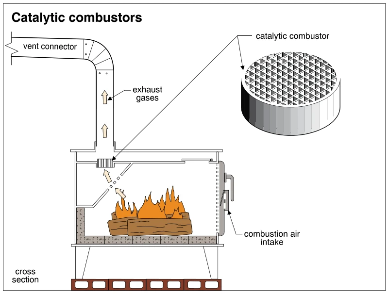 1040
1040Catalytic combustors
· p. 180
A cross section of a wood-burning space heater shows burning logs in a lined firebox and a combustion air intake at the front. Arrows trace exhaust gases upward through a catalytic combustor near the top of the stove and into the vent connector. Internal baffles direct the gases toward the combustor. An enlarged detail shows the combustor as a round, thick element with numerous small honeycomb-like passages.
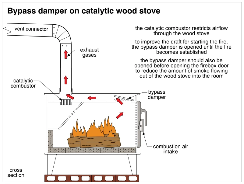 1041
1041Bypass damper on catalytic wood stove
· p. 180
A cross section of a catalytic wood stove shows burning logs in a lined firebox, a front combustion air intake, and a vent connector rising from the rear. The catalytic combustor is positioned beneath the vent outlet, while a bypass damper is located near the front of the upper firebox. Red arrows illustrate exhaust gases traveling through the open bypass route and into the vent connector. The annotations explain that the combustor restricts airflow and that opening the bypass improves draft during fire startup. They also advise opening the bypass before the firebox door to reduce smoke spilling into the room.
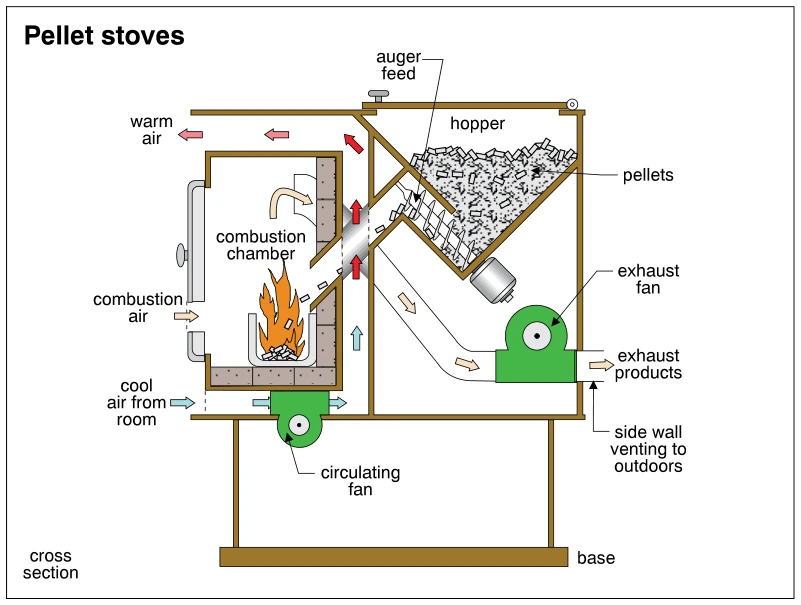 1042
1042Pellet stoves
· p. 180
A cross section of a pellet stove shows a fuel hopper and powered auger feeding pellets into a burn pot within the combustion chamber. Combustion air enters from the left to support the fire. A circulating fan draws cool room air through the lower portion of the stove and moves it around the combustion chamber, with warm air discharged at the upper left. A separate exhaust fan draws combustion products through an internal passage and discharges them through side wall venting to outdoors. Arrows distinguish the room-air circulation and combustion-exhaust paths.
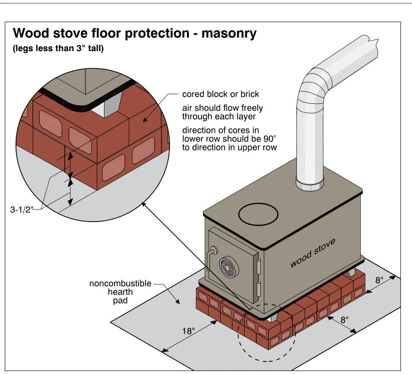 1043
1043Wood stove floor protection - masonry
· p. 181
The illustration shows a short-legged wood stove supported on two layers of cored masonry over a noncombustible hearth pad. An enlarged detail specifies cored block or brick, with the cores in the lower row oriented 90° to those in the upper row and free airflow through each layer. A 3-1/2-inch dimension is indicated at the masonry layers. The hearth pad extends beyond the masonry base, with an 18-inch dimension at the loading-door end and 8-inch dimensions at the side and rear. A metal stovepipe rises from the stove and bends toward the upper right.
 1044
1044Wood stove floor protection - masonry
· p. 181
The illustration shows a leg-supported wood stove on a single layer of cored masonry above a noncombustible hearth pad. A magnified detail identifies the masonry as cored block or brick, shows a 3-1/2-inch thickness, and specifies that air should flow freely through the cores. The detail applies to stove legs 3 to 7 inches tall. Dimension arrows show hearth-pad extensions of 18 inches in front and 8 inches at the side and rear of the masonry base. A stovepipe rises from the stove and turns through an elbow.
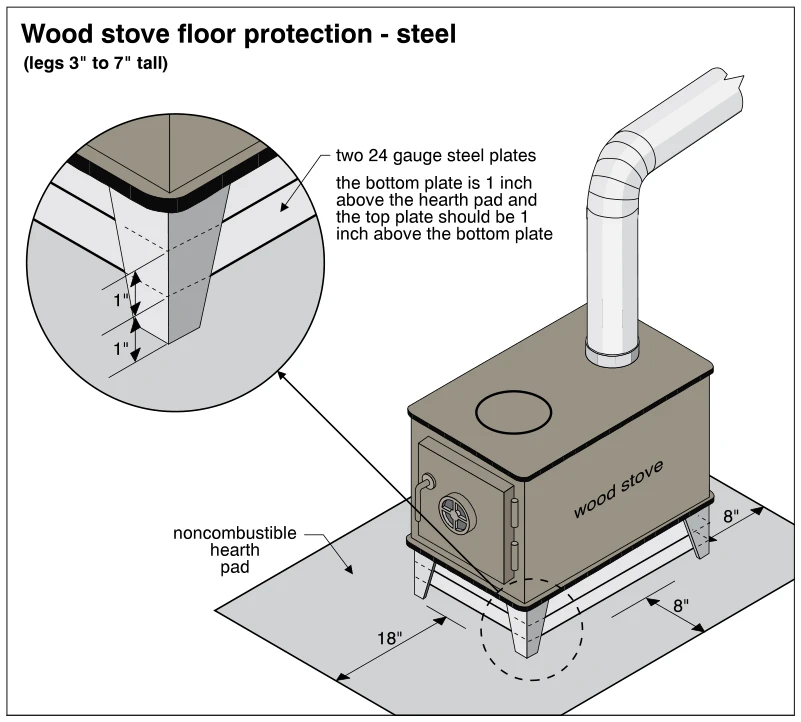 1045
1045Wood stove floor protection - steel
· p. 181
The illustration shows a freestanding wood stove with legs 3 to 7 inches tall on a noncombustible hearth pad. Two 24-gauge steel plates are positioned beneath the stove, with the bottom plate 1 inch above the pad and the upper plate 1 inch above the bottom plate. A magnified detail at a stove leg illustrates these vertical separations. The hearth pad extends 18 inches in front of the loading door and 8 inches beyond the side and rear of the stove. A stovepipe rises from the stove top and bends toward the upper right.
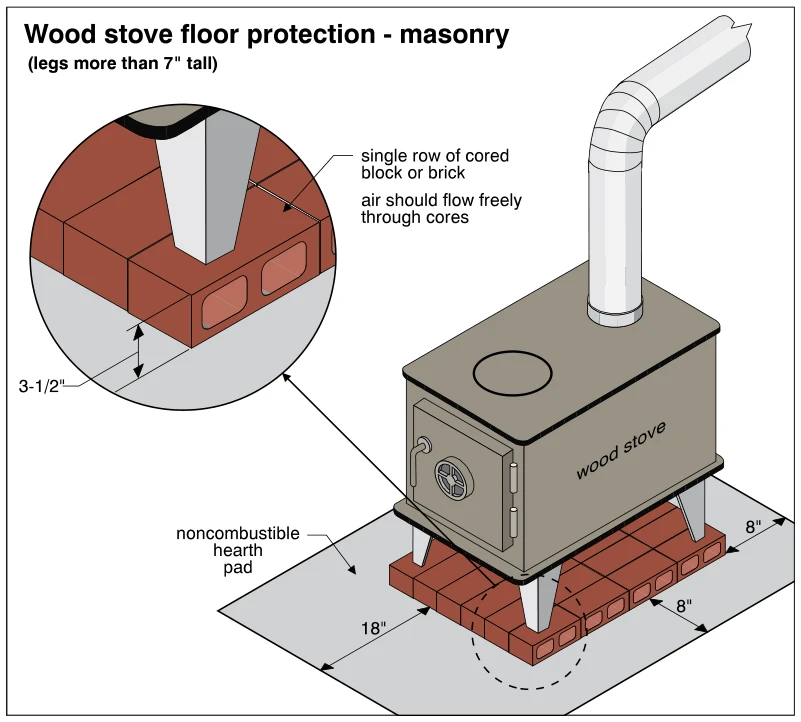 1046
1046Wood stove floor protection - masonry
· p. 181
The illustration shows a leg-supported wood stove on a single layer of cored masonry over a noncombustible hearth pad. The figure applies to stoves with legs more than 7 inches tall. An enlarged detail identifies 3-1/2-inch-thick cored block or brick and specifies that air should flow freely through the cores. The hearth pad is shown extending 18 inches in front of the masonry base and 8 inches at the side and rear. A metal stovepipe rises from the stove top and turns through an elbow.
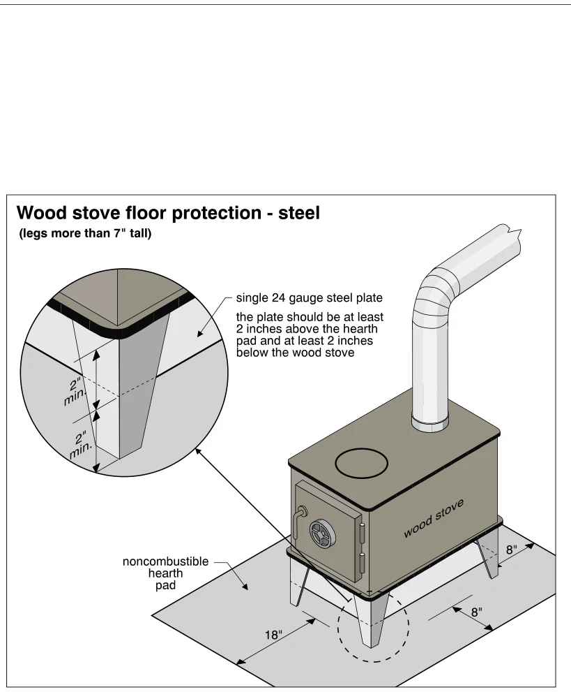 1047
1047Wood stove floor protection - steel
· p. 182
The illustration shows a freestanding wood stove with legs more than 7 inches tall installed over a noncombustible hearth pad. A magnified detail shows a single 24 gauge steel plate beneath the stove, with at least 2 inches of clearance above the hearth pad and at least 2 inches below the stove body. Dimension arrows show the hearth pad extending 18 inches in front of the stove and 8 inches at the side and rear. The stove has a front loading door and a top-mounted flue connector that rises vertically before turning through an elbow.
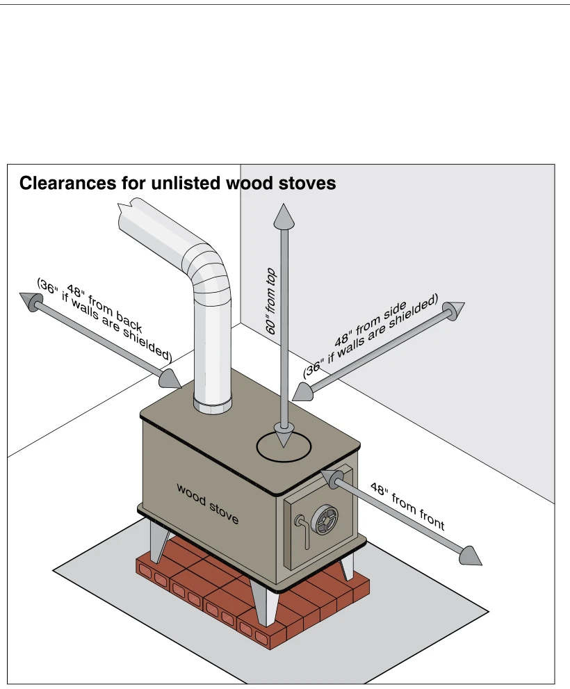 1048
1048Clearances for unlisted wood stoves
· p. 182
The illustration shows a freestanding unlisted wood stove near a wall corner, with a stovepipe rising from its top and turning through an elbow. Dimension arrows indicate clearances of 48 inches from the back, side, and front, and 60 inches above the stove top. The back and side annotations specify reduced clearances of 36 inches if the walls are shielded. The stove stands on legs over a brick platform placed on a larger floor-protection sheet.
 1049
1049Vent connector clearances
· p. 182
The illustration shows a freestanding wood stove with a vent connector rising vertically from its top and turning through an elbow into an inclined section. Four arrows labeled 18 inches extend outward from the vertical connector, indicating clearance to surrounding combustible surfaces in all directions. An oval outline emphasizes the clearance zone around the pipe. The stove stands on legs over a brick pad and a larger underlying protective sheet near a wall corner.
 1050
1050Wall shields - metal
· p. 182
The illustration shows a freestanding wood stove protected by a metal wall shield, with a perspective drawing and a side-view inset. Noncombustible spacers hold the shield 1 inch away from the wall. The inset shows the shield extending 18 inches beyond each side of the stove and 20 inches above its top, with a 1-inch gap below the shield and a labeled 3-inch gap above. The shield is specified as 29 gauge sheet metal, or bricks, ceramic tiles, or other noncombustible material attached to that sheet metal. The stove stands on a brick base over a larger floor-protection sheet; its vent connector is explicitly not shown. An annotation states that manufacturers' recommended clearances can be reduced by 67% with wall shields installed as shown.
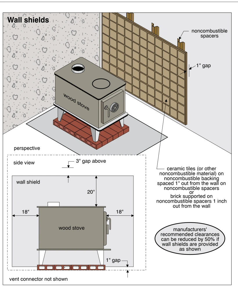 1051
1051Wall shields
· p. 183
The illustration shows a wood stove on a brick base over a floor-protection sheet, with a tiled wall shield behind it. Noncombustible spacers hold the shield 1 inch away from the wall. A side-view inset shows the shield extending 18 inches beyond each side of the stove and 20 inches above its top, with a 1-inch bottom gap and a labeled 3-inch gap above the shield. The annotation identifies ceramic tile or other noncombustible material on noncombustible backing, or brick, as shield options. It states that manufacturers' recommended clearances can be reduced by 50% with shields installed as shown; the vent connector is explicitly omitted.
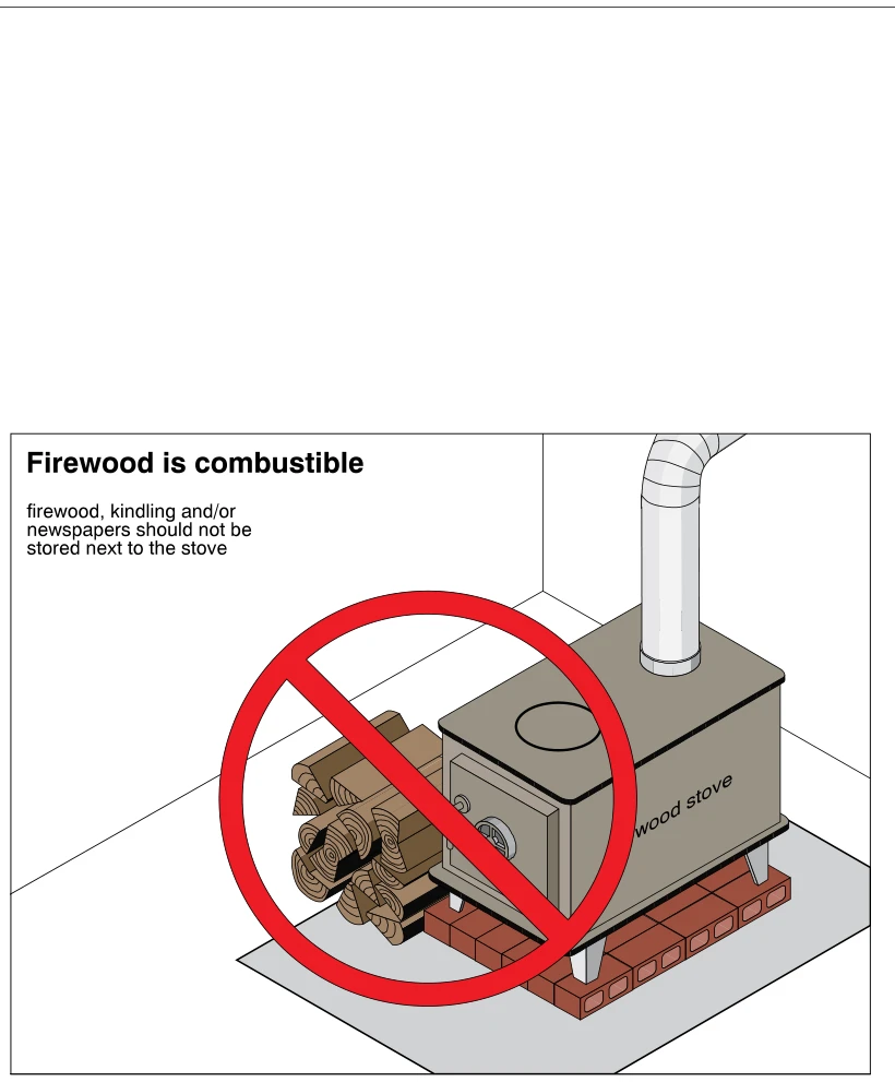 1052
1052Firewood is combustible
· p. 183
A freestanding wood stove sits on legs above a brick hearth and a larger floor-protection pad. A stovepipe rises from the top of the stove and bends near the upper edge of the drawing. Split firewood is stacked immediately beside the stove. A large red prohibition symbol identifies this combustible storage arrangement as unsafe, and the annotation warns against storing firewood, kindling, or newspapers next to the stove.
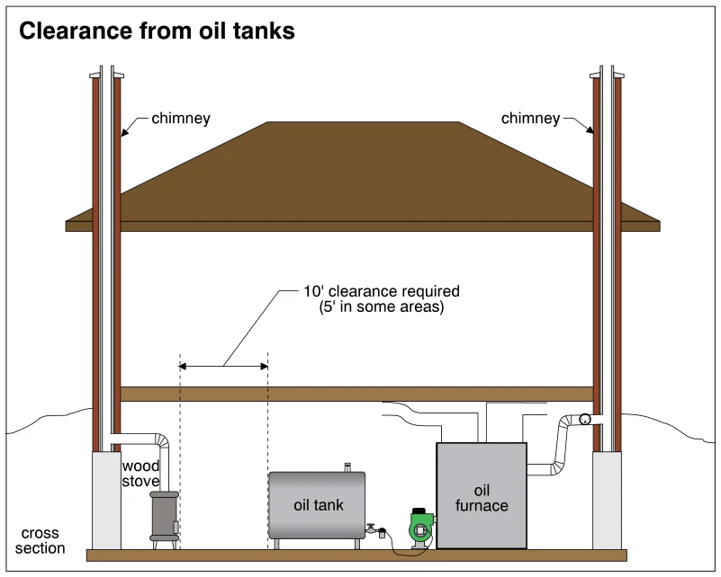 1053
1053Clearance from oil tanks
· p. 183
A house cross section shows a wood stove and an oil furnace in a basement, each connected to a separate chimney. An oil storage tank sits between the two heating appliances and is connected by a fuel line to the oil burner at the furnace. A horizontal dimension marks the separation between the wood stove and the nearest side of the oil tank. The annotation specifies 10 feet of required clearance, with 5 feet noted for some areas.
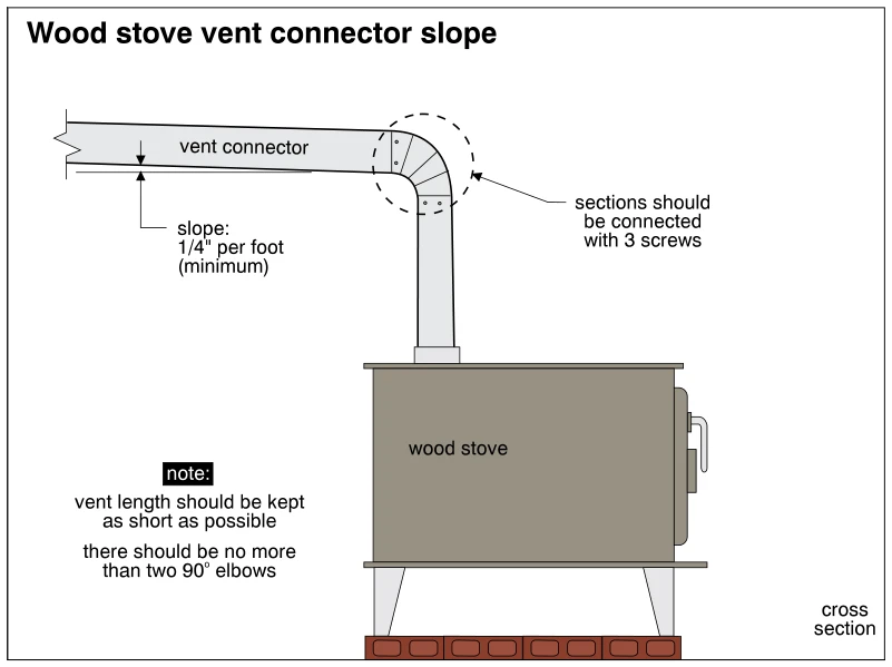 1054
1054Wood stove vent connector slope
· p. 183
The illustration shows a wood stove on legs over a brick base, with a vent connector rising vertically from the stove top and turning through a 90° elbow. The near-horizontal connector slopes upward away from the stove at a minimum of 1/4 inch per foot. A dashed circle highlights the elbow joints, with an annotation requiring sections to be connected with three screws. Notes specify keeping the vent length as short as possible and using no more than two 90° elbows.
Wood Heating Systems ·Wood Burning Fireplacesp. 184
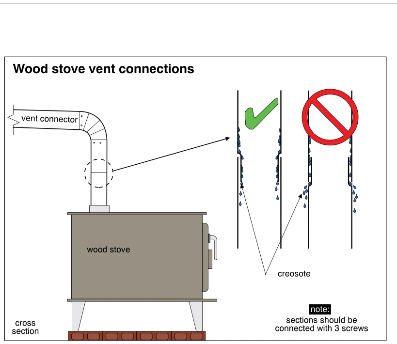 1055
1055Wood stove vent connections
· p. 184
A wood stove stands on a brick base with a vertical vent connector that turns through an elbow into a horizontal run. A circled joint is enlarged in two cross-sectional details comparing proper and improper pipe overlap. The green check marks an upper pipe end inserted inside the lower section, keeping descending creosote within the connector. The red prohibition symbol marks the reverse overlap, which allows creosote to escape at the joint. A note specifies that sections should be connected with three screws.
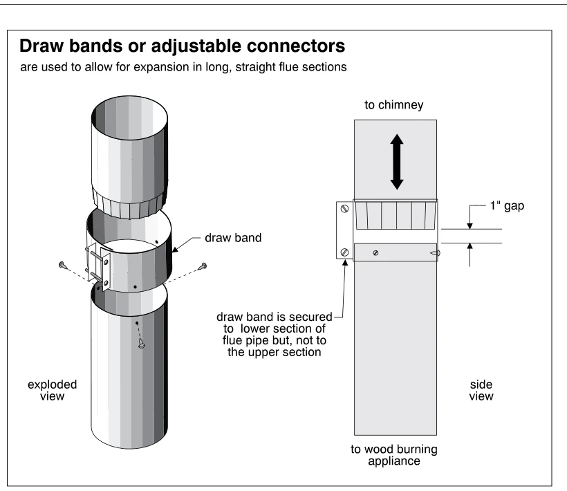 1056
1056Draw bands or adjustable connectors
· p. 184
The illustration shows exploded and side views of a draw band joining two straight sections of metal flue pipe for a wood-burning appliance. The upper section leads to the chimney, and the lower section leads to the appliance. The draw band surrounds the joint and is secured to the lower pipe section but not to the upper section. A 1-inch gap and a vertical double-headed arrow indicate allowance for movement as the long, straight flue sections expand.
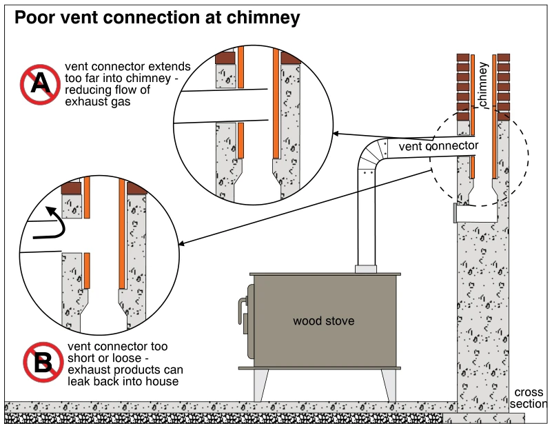 1057
1057Poor vent connection at chimney
· p. 184
The illustration shows a wood stove connected to a masonry chimney by a vent connector that rises vertically and turns through an elbow into the chimney. The chimney is shown in cross section, exposing its flue liner and connector entry. Enlarged detail A shows the connector extending too far into the flue, restricting exhaust-gas flow. Enlarged detail B shows a connector that is too short or loose, allowing exhaust products to leak back into the house. Both connection conditions are marked as improper.
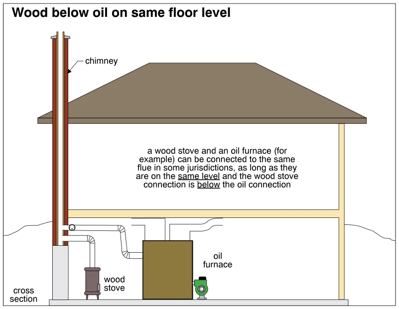 1058
1058Wood below oil on same floor level
· p. 184
A house cross section shows a wood stove and an oil furnace on the same lower floor, connected to a common chimney flue. The wood stove connector enters the chimney below the oil furnace connector. The chimney extends upward past the roof. The annotation states that this shared-flue arrangement is permitted in some jurisdictions when the appliances are on the same level and the wood stove connection is below the oil connection.
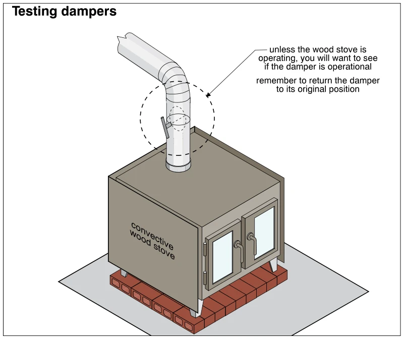 1059
1059Testing dampers
· p. 184
The illustration shows a freestanding convective wood stove with two glazed front doors, supported on legs over a brick base and a larger floor pad. A metal stovepipe rises from the stove top and turns through an elbow. A dashed circle highlights the manual damper and its external operating handle in the vertical stovepipe section. The annotations instruct the inspector to check damper operation unless the stove is operating and to return the damper to its original position after testing.
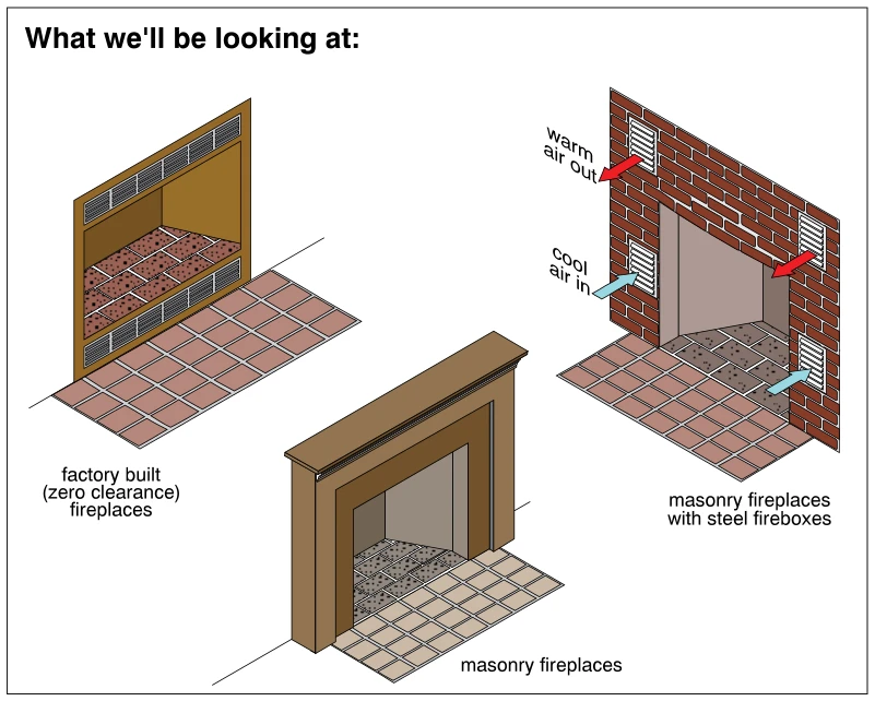 1060
1060What we'll be looking at:
· p. 184
The illustration presents three types of wood-burning fireplaces: factory-built (zero-clearance) fireplaces, masonry fireplaces, and masonry fireplaces with steel fireboxes. Each is shown with an open firebox and a hearth extension projecting into the room. The factory-built unit has grilles above and below its opening, while the masonry fireplace at the bottom has a mantel and surround. The masonry fireplace with a steel firebox has a brick facing and side grilles, with blue arrows indicating cool air entering the lower grilles and red arrows indicating warm air leaving the upper grilles. No defects or improper installation practices are identified.
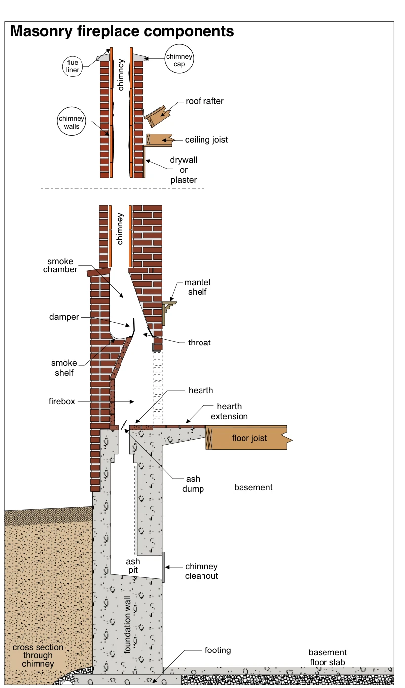 1061
1061Masonry fireplace components
· p. 185
The illustration shows a cross section through a masonry wood-burning fireplace and chimney, from the footing and basement ash pit to the lined chimney and chimney cap. The firebox connects through the throat and damper to the smoke chamber, with a smoke shelf behind the damper. A mantel shelf projects above the fireplace opening, and the hearth extension projects toward the adjacent wood floor joist. An ash dump in the hearth leads into an ash pit with a chimney cleanout accessible from the basement. The upper detail shows the flue liner within masonry chimney walls and adjacent roof and ceiling framing with drywall or plaster finish. No specific defects or incorrect practices are identified.
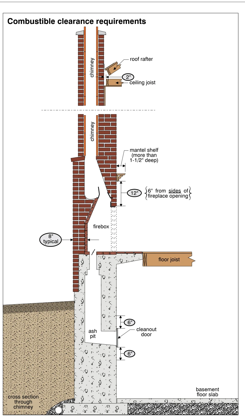 1062
1062Combustible clearance requirements
· p. 185
The illustration shows a cross section through a masonry wood-burning fireplace, chimney, and supporting foundation with an ash pit and basement cleanout door. The upper detail indicates a 2-inch clearance between the chimney masonry and adjacent combustible roof and ceiling framing. A mantel shelf projecting more than 1-1/2 inches is shown with a 12-inch clearance above the fireplace opening, with an annotation specifying 6 inches from the sides of the opening. The firebox wall is dimensioned as 8 inches typical, and the hearth lies above the ash pit beside a wood floor joist. Two 6-inch dimensions are marked in the foundation wall immediately above and below the cleanout door.
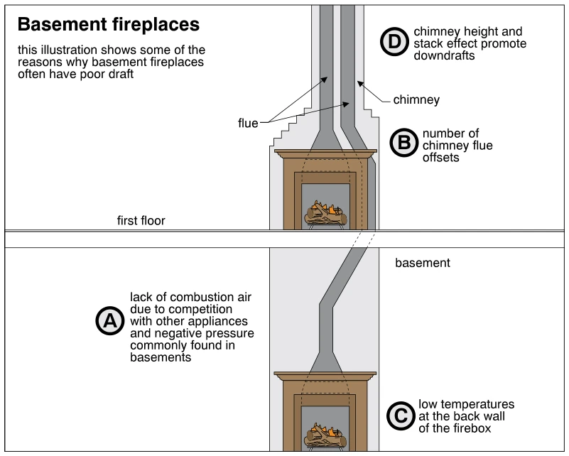 1063
1063Basement fireplaces
· p. 185
The illustration shows a section through first-floor and basement wood-burning fireplaces connected to separate flues in a common chimney assembly. The basement fireplace flue offsets around the upper fireplace before continuing upward. Annotations identify inadequate combustion air, competition with other appliances, and basement negative pressure as contributors to poor draft. Additional factors identified are flue offsets, low temperatures at the firebox back wall, and chimney height and stack effect promoting downdrafts.
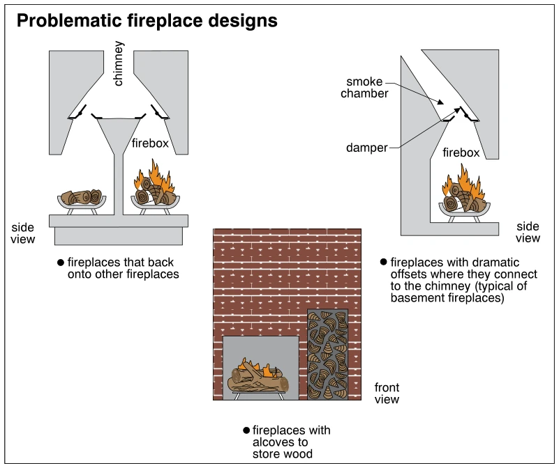 1064
1064Problematic fireplace designs
· p. 185
The illustration presents three problematic wood-burning fireplace designs. A side section shows back-to-back fireplaces with separate fireboxes opening toward a shared chimney passage. A second side section shows a fireplace with a dramatically offset smoke chamber at its connection to the chimney, with the damper identified at the firebox throat. A front view shows a brick fireplace with a tall, wood-filled storage alcove directly beside the firebox. All three arrangements are identified as problematic designs.
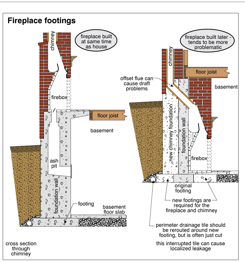 1065
1065Fireplace footings
· p. 186
Two cross sections compare a masonry fireplace built with the house with a basement fireplace added later. The original installation shows a firebox above an ash pit, supported by a foundation wall and footing beside the basement floor slab. The later installation shows a new chimney foundation alongside the existing foundation wall, with an offset flue connecting the basement firebox to the chimney. Annotations identify potential draft problems at the offset and the need for new fireplace and chimney footings. The drawing also warns that perimeter drainage tile must be rerouted around the new footing rather than cut, since interrupted drainage can cause localized leakage.
 1066
1066Causes of chimney settling or leaning
· p. 186
Three cutaway views show exterior masonry chimneys alongside a house, with their below-grade supports exposed. Curved arrows above each chimney indicate potential leaning, while arrows beside the excavated soil indicate ground movement. The left view identifies weak or disturbed soils, expansive clay movement, frost heave, and tree roots as causes of settlement or leaning. The center view shows cracked and deteriorating chimney support, and the right view illustrates undersized or missing footings.
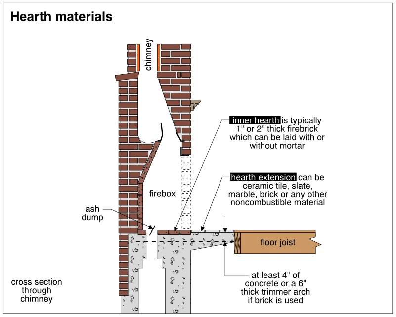 1067
1067Hearth materials
· p. 186
The illustration shows a cross section through a masonry wood-burning fireplace and chimney, including the firebox, ash dump, inner hearth, and hearth extension. The inner hearth is identified as typically 1 or 2 inches of firebrick, laid with or without mortar. The hearth extension projects in front of the firebox toward the wood floor framing and may be finished with ceramic tile, slate, marble, brick, or another noncombustible material. Its supporting construction is specified as at least 4 inches of concrete or a 6-inch-thick trimmer arch if brick is used. No defective condition is depicted.
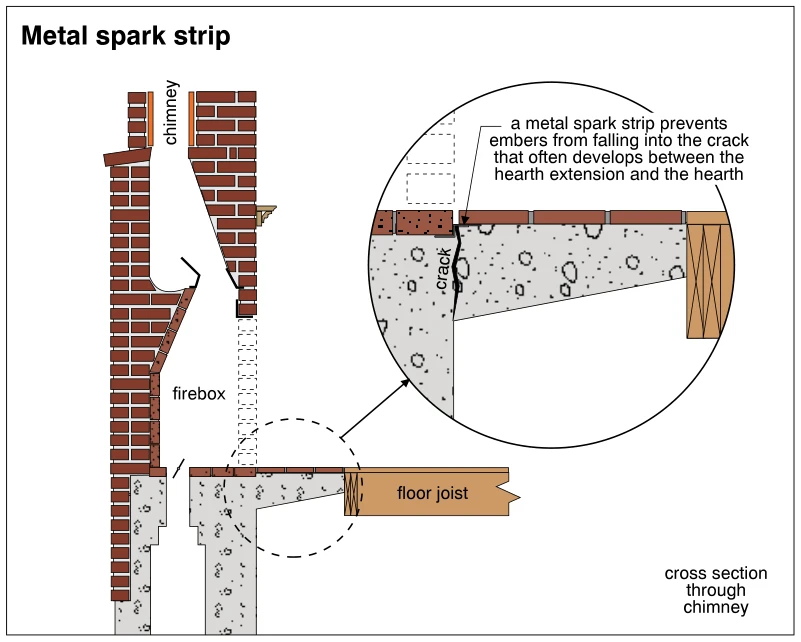 1068
1068Metal spark strip
· p. 186
The illustration shows a cross section through a masonry chimney and wood-burning fireplace, including the firebox, hearth, hearth extension, and adjacent wood floor joist. An enlarged detail shows a crack at the junction between the hearth and hearth extension. A metal spark strip bridges this joint beneath the masonry surface. The strip prevents embers from falling into the crack at the hearth-to-extension junction.
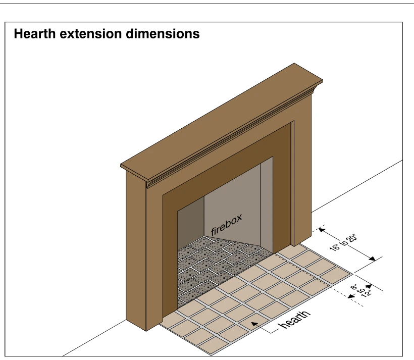 1069
1069Hearth extension dimensions
· p. 187
The illustration shows a wood-burning fireplace with a mantel, surround, firebox, and tiled hearth extension. The hearth extends outward from the fireplace opening and beyond both sides of the opening. Dimension arrows indicate a front extension of 16 to 20 inches and a side extension of 8 to 12 inches. Brick-pattern masonry forms the firebox floor, adjoining the tiled hearth extension. No damage or improper installation is depicted.
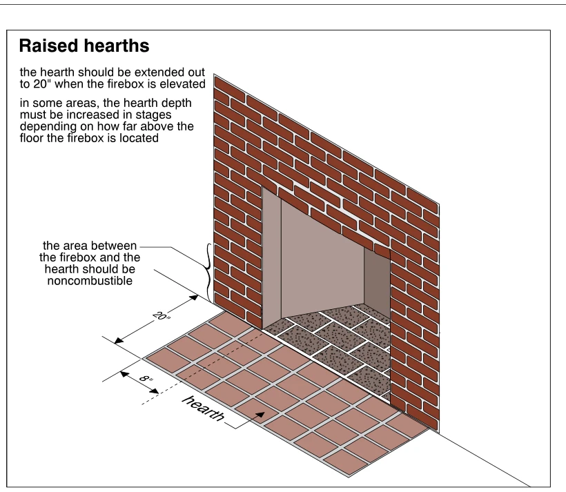 1070
1070Raised hearths
· p. 187
The illustration shows a brick-faced wood-burning fireplace with a raised firebox and a tiled hearth extension in front. A dimension indicates a 20-inch hearth projection, and another indicates an 8-inch extension beyond the side of the opening. The annotation specifies that the area between the firebox and the hearth should be noncombustible. Additional text notes that some areas require hearth depth to increase in stages with the height of the firebox above the floor.
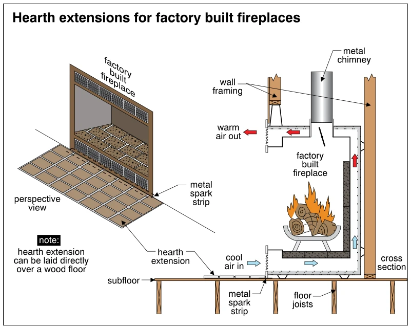 1071
1071Hearth extensions for factory built fireplaces
· p. 187
The illustration shows perspective and cross-sectional views of a factory-built wood-burning fireplace with a hearth extension in front of its opening. A metal spark strip bridges the junction between the fireplace and hearth extension. The cross section shows the fireplace supported over a subfloor and floor joists, with wall framing behind and a metal chimney above. Arrows indicate cool air entering the lower grille, circulating around the firebox, and exiting as warm air through the upper grille. A note states that the hearth extension can be laid directly over a wood floor.
 1072
1072Remove hearth extension forming boards
· p. 187
The illustration shows a cross section through a masonry fireplace and chimney, with a concrete hearth extension adjoining a wood floor joist. A circular enlargement highlights a forming board remaining beneath the concrete hearth extension. A crack is identified in the concrete above the board. The annotation specifies that forming boards should be removed after the concrete has cured.
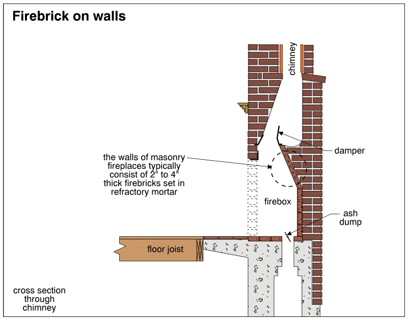 1073
1073Firebrick on walls
· p. 187
The illustration shows a cross section through a masonry fireplace and chimney, with a firebrick-lined firebox. The annotation specifies that masonry fireplace walls typically consist of 2" to 4" thick firebricks set in refractory mortar. The rear firebox wall slopes inward toward the throat, where a damper is shown below the chimney passage. An ash dump opens through the firebox floor into a cavity below, and a wood floor joist meets the edge of the masonry hearth support.
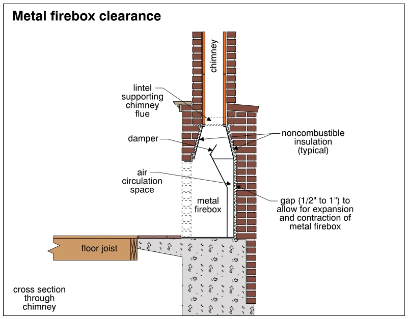 1074
1074Metal firebox clearance
· p. 187
The illustration shows a cross section through a metal fireplace firebox within a masonry chimney assembly. The firebox connects to the chimney flue through a tapered throat with a damper, and a lintel is identified as supporting the chimney flue. Callouts identify an air circulation space and noncombustible insulation around the firebox assembly. A 1/2-inch to 1-inch gap between the metal firebox and surrounding masonry allows for expansion and contraction. A wood floor joist is shown adjacent to the masonry support beneath the fireplace.
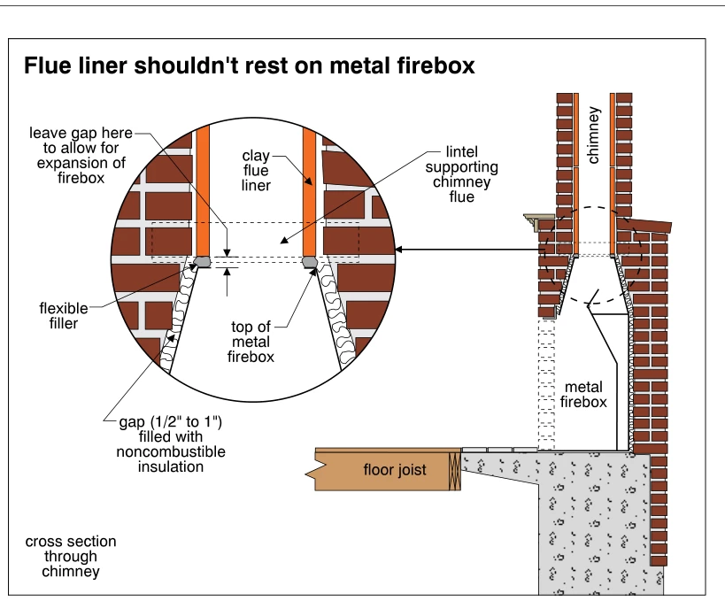 1075
1075Flue liner shouldn't rest on metal firebox
· p. 188
The illustration shows a cross section through a masonry chimney and metal wood-burning fireplace firebox, with an enlarged detail of the flue-to-firebox junction. A lintel supports the clay chimney flue independently of the metal firebox. A gap beneath the flue liner allows the firebox to expand without bearing against the liner. Flexible filler is indicated at the junction, and a 1/2-inch to 1-inch gap alongside the firebox is filled with noncombustible insulation. The larger section also shows the masonry surround, foundation support, and an adjacent floor joist.
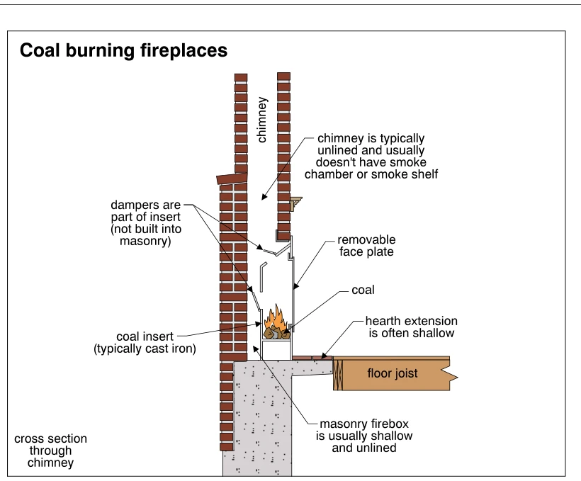 1076
1076Coal burning fireplaces
· p. 188
The illustration shows a cross section through a coal-burning masonry fireplace and chimney. A coal insert, identified as typically cast iron, sits inside a shallow masonry firebox and has integral dampers and a removable face plate. Burning coal is shown in the lower portion of the insert, beneath the chimney passage. Annotations identify the chimney as typically unlined and usually lacking a smoke chamber or smoke shelf, and the masonry firebox as usually shallow and unlined. A shallow hearth extension projects over masonry support beside a wood floor joist.
 1077
1077Lintel rusting, sagging or loose
· p. 188
The illustration shows a cross section and perspective view of a masonry wood-burning fireplace, with an enlarged detail of the lintel supporting the brickwork above the firebox opening. The detail identifies a crack in the masonry above the lintel, and downward arrows indicate sagging or displacement. The annotation explains that rusting caused by water leakage from above, or an undersized lintel, can cause cracking of the fireplace face. The cross section also shows the chimney passage, firebox, hearth support, and an adjacent floor joist.
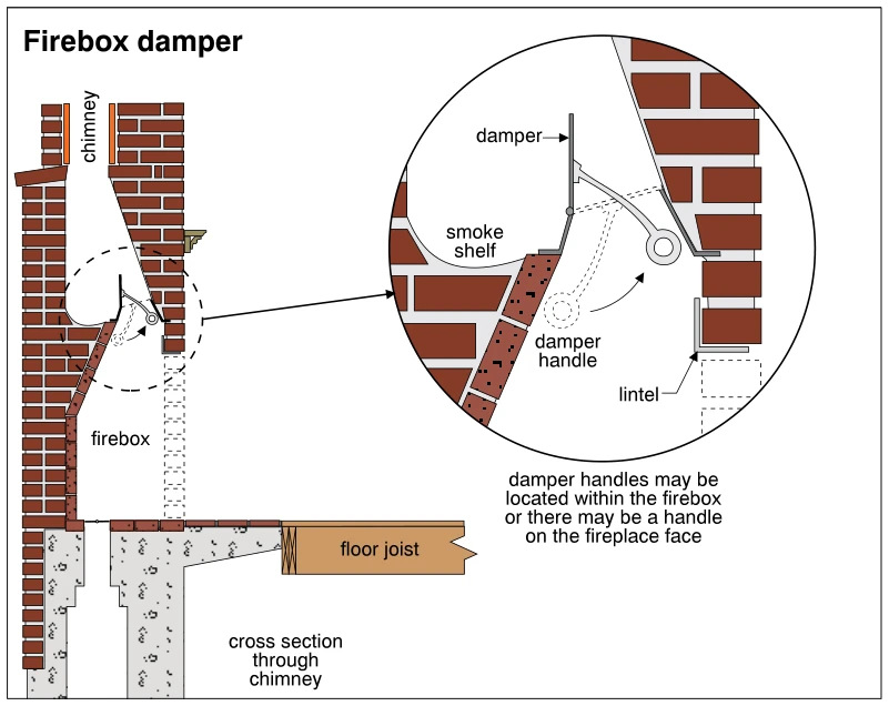 1078
1078Firebox damper
· p. 188
A cross section through a masonry fireplace and chimney shows the firebox, sloped rear wall, smoke shelf, and damper at the fireplace throat. An enlarged circular detail shows the damper plate and operating handle, with dashed outlines and an arrow illustrating movement between positions. The lintel supports the masonry above the fireplace opening. The drawing also shows the fireplace base and an adjacent floor joist. An annotation explains that damper handles may be inside the firebox or on the fireplace face.
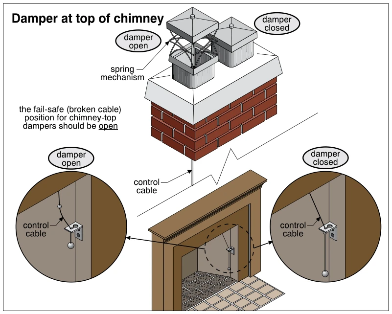 1079
1079Damper at top of chimney
· p. 188
The illustration shows chimney-top dampers in open and closed positions above a brick chimney. A spring mechanism lifts the open damper lid above the flue opening, while the closed lid seats over the opening. A control cable extends down to the fireplace, where enlarged details show its positions at a mounting bracket for open and closed operation. An annotation specifies that the fail-safe position following a broken control cable should be open.
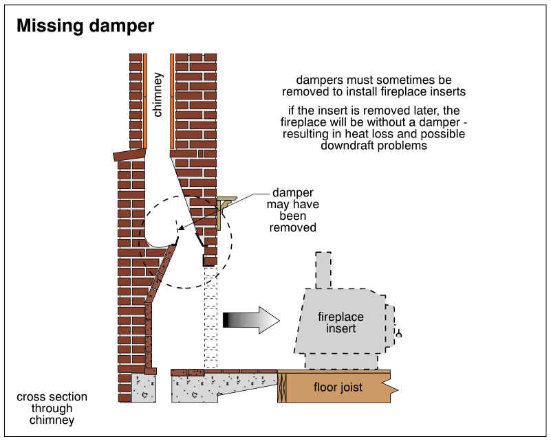 1080
1080Missing damper
· p. 188
The illustration shows a cross section through a masonry wood-burning fireplace and chimney, with the damper location circled at the fireplace throat. A dashed outline of a fireplace insert and a right-pointing arrow depict removal of the insert from the firebox. The annotations explain that dampers must sometimes be removed to install fireplace inserts. If the insert is subsequently removed without restoring the damper, the fireplace remains open to the chimney, resulting in heat loss and possible downdraft problems.
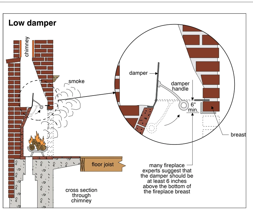 1081
1081Low damper
· p. 189
The illustration shows a cross section through a masonry wood-burning fireplace and chimney, with smoke spilling out of the fireplace opening. A circular enlargement details the throat damper, its pivoting blade and handle, and its relationship to the fireplace breast. Solid and dashed outlines illustrate the damper mechanism and an alternate lower position. A dimension and note indicate that many fireplace experts recommend locating the damper at least 6 inches above the bottom of the fireplace breast. The lower section also shows the masonry support beneath the hearth and an adjacent floor joist.
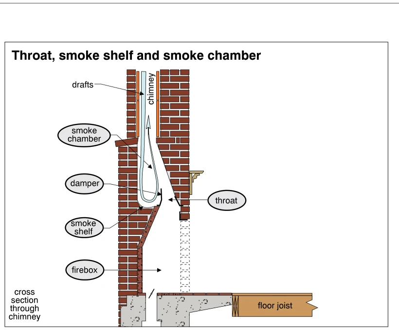 1082
1082Throat, smoke shelf and smoke chamber
· p. 189
The illustration shows a vertical cross section through a masonry wood-burning fireplace and chimney. The firebox has a sloping rear wall leading up to the smoke shelf, with the throat and damper above the firebox opening. The smoke chamber narrows upward into the chimney flue. Arrows illustrate downward drafts toward the smoke shelf and upward airflow into the chimney. A concrete support beneath the fireplace and an adjacent wood floor joist are also shown.
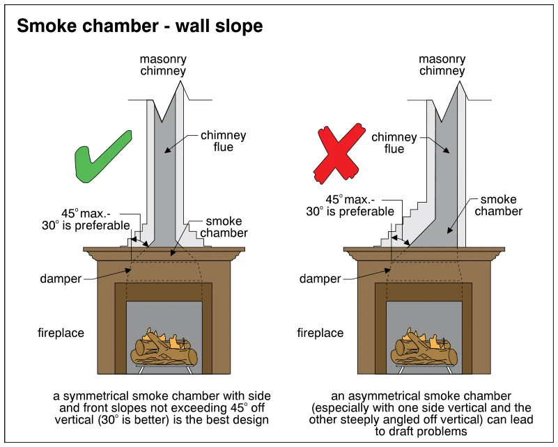 1083
1083Smoke chamber - wall slope
· p. 189
Two cutaway diagrams compare smoke chamber wall slopes above wood-burning fireplaces in masonry chimneys. The left diagram, marked with a green check, shows a symmetrical smoke chamber tapering toward a centered chimney flue. Its annotation recommends side and front slopes no greater than 45° off vertical, with 30° preferred. The right diagram, marked with a red X, shows an asymmetrical chamber leading to an offset flue, with one side vertical and the other steeply angled off vertical. The caption warns that this arrangement can lead to draft problems; both diagrams identify the damper below the smoke chamber.
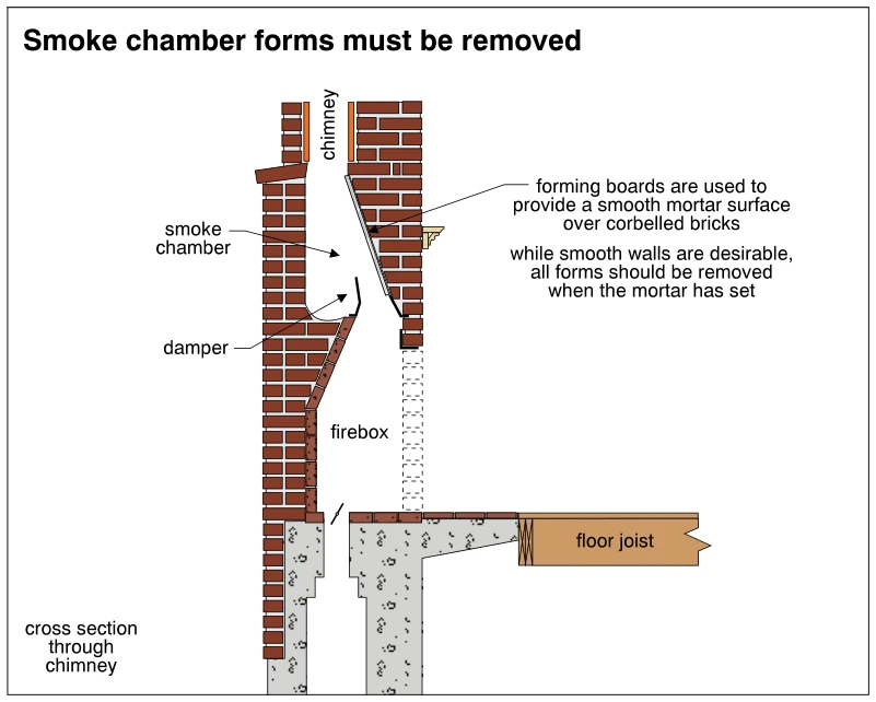 1084
1084Smoke chamber forms must be removed
· p. 189
A cross section through a masonry fireplace and chimney shows the firebox, damper, and tapered smoke chamber leading to the chimney flue. Corbelled bricks form the sloping side of the smoke chamber, with forming boards used to create a smooth mortar surface over the bricks. The annotation states that all forms must be removed after the mortar has set, even though smooth chamber walls are desirable. The lower section shows the masonry support beneath the fireplace and an adjacent wood floor joist.
 1085
1085Fireplace breast
· p. 189
The illustration shows a cross section through a masonry wood-burning fireplace and chimney, including the firebox, damper, fireplace breast, and adjacent floor joist. A circular enlargement details the lintel supporting the brickwork above the fireplace opening. The fireplace breast is dimensioned as typically 4 to 6 inches thick. An annotation warns that fireplace breasts thicker than 6 inches may cause chimney draft problems.
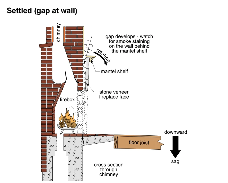 1086
1086Settled (gap at wall)
· p. 189
The illustration shows a cross section through a masonry wood-burning fireplace and chimney, with a stone veneer fireplace face and mantel shelf. Rotation of the fireplace breast is indicated by a curved arrow, with a gap developing at the wall behind the mantel shelf. An annotation advises watching for smoke staining at this gap. Below the firebox, a crack is shown in the supporting masonry or concrete, and the adjoining floor joist slopes downward toward an arrow labeled downward sag.
 1087
1087Clearance from fireplace opening
· p. 190
The illustration shows a wood-burning fireplace with a noncombustible face, combustible mantel shelf and side trim, and a tiled hearth. A perspective view marks a 6-inch side clearance from the fireplace opening to combustible trim and a 6- to 12-inch clearance above the opening. Side-view detail A shows a 6-inch vertical clearance where combustibles project 1-1/2 inches or less from the face of the opening. Detail B shows a 12-inch vertical clearance where combustibles project more than 1-1/2 inches.
 1088
1088Ashpit
· p. 190
The illustration shows a cross section through a masonry fireplace and chimney with an ash dump opening into an ash pit within the foundation below. A cleanout door provides access to the bottom of the pit from the basement side, adjacent to wood wall framing. An enlarged detail specifies a minimum 6-inch clearance to combustibles above and below the cleanout door. Notes specify ashpit walls at least 4 inches thick, removal of wood forms, and a pit bottom ideally no lower than the cleanout door for easier cleaning.
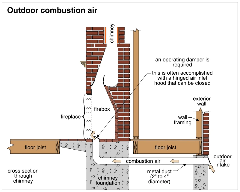 1089
1089Outdoor combustion air
· p. 190
A cross section through a masonry fireplace and chimney shows an outdoor combustion-air supply routed beneath the floor. A metal duct, labeled 2 to 4 inches in diameter, runs from an exterior wall intake through the chimney foundation and turns upward into the firebox. Arrows indicate air moving from outdoors toward the fireplace. The drawing specifies an operating damper, often provided by a hinged air inlet hood that can be closed at the firebox inlet. Floor joists, wall framing, and masonry surround the air-supply route.
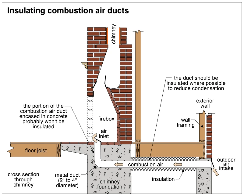 1090
1090Insulating combustion air ducts
· p. 190
The illustration shows a cross section through a masonry fireplace and chimney with a metal combustion air duct connecting an outdoor intake to an inlet at the base of the firebox. Arrows indicate outdoor air traveling horizontally beneath the floor and then turning upward through the chimney foundation into the fireplace. Insulation surrounds the accessible horizontal duct to reduce condensation. The portion encased in the concrete chimney foundation is identified as likely to remain uninsulated.
Steam Heating Systems ·How They Workp. 191
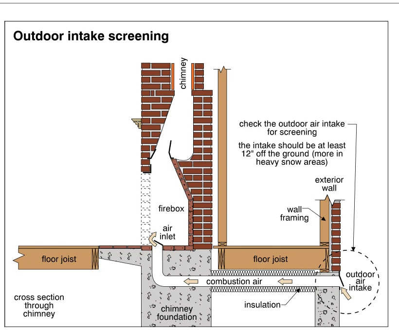 1091
1091Outdoor intake screening
· p. 191
The illustration shows a cross section through a masonry fireplace and chimney with an outdoor combustion-air supply duct. The duct passes through the exterior wall below the floor framing, runs through the chimney foundation, and turns upward to an air inlet at the base of the firebox. Arrows indicate outdoor air flowing toward the fireplace, and insulation is shown around the horizontal duct. An annotation directs the inspector to check the outdoor intake for screening and specifies a minimum height of 12 inches above ground, with greater clearance in heavy snow areas.
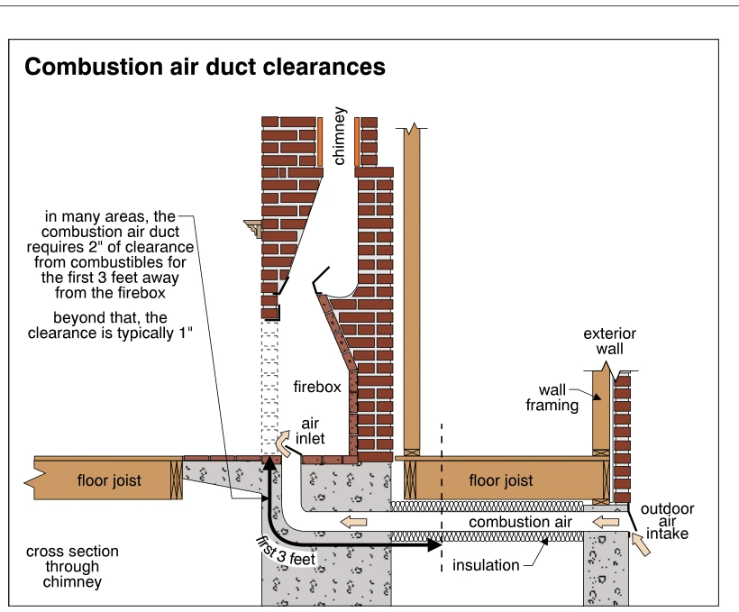 1092
1092Combustion air duct clearances
· p. 191
The illustration shows a cross section through a masonry fireplace and chimney with a combustion air duct running beneath the floor to an outdoor air intake at the exterior wall. Arrows indicate outdoor air traveling through the insulated duct and turning upward to an air inlet at the base of the firebox. Wood floor joists and exterior wall framing are shown adjacent to the masonry and duct assembly. A dimension marks the first 3 feet of duct from the firebox, where the annotation states that many areas require 2 inches of clearance from combustibles. Beyond this distance, the stated typical clearance is 1 inch.
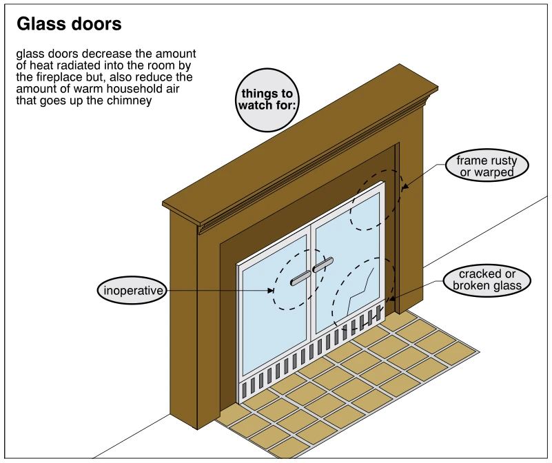 1093
1093Glass doors
· p. 191
The illustration shows a fireplace with a pair of framed glass doors, central handles, and a slotted grille beneath the doors. A mantel and surround frame the opening, and a tiled hearth extends into the room. Dashed circles and callouts identify inspection concerns: a rusty or warped frame, inoperative doors, and cracked or broken glass. The accompanying note explains that glass doors reduce heat radiated into the room but also reduce the loss of warm household air up the chimney.
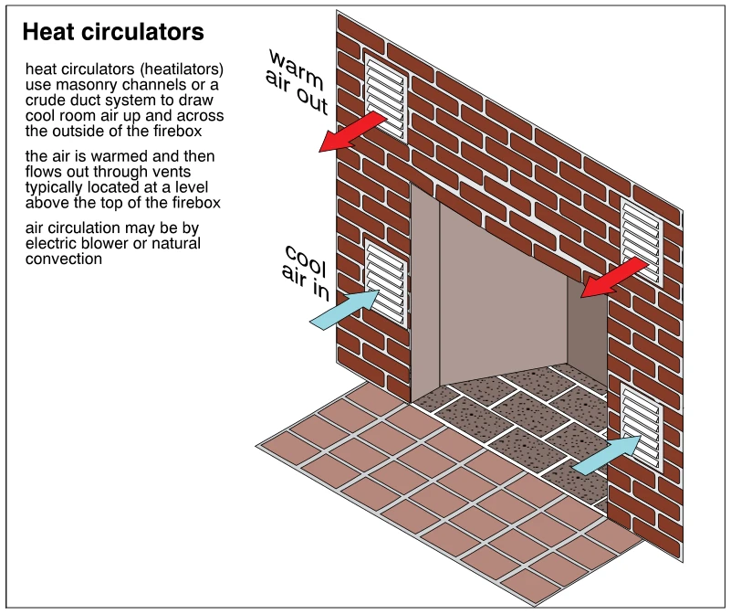 1094
1094Heat circulators
· p. 191
The illustration shows a masonry fireplace with two lower air-inlet grilles and two upper warm-air outlet grilles flanking the firebox. Blue arrows indicate cool room air entering the lower grilles, and red arrows indicate warmed air returning to the room through the upper grilles. The annotations explain that masonry channels or ducts carry air up and across the outside of the firebox to absorb heat. Air circulation may be driven by an electric blower or natural convection, although the internal passages and blower are not shown. A masonry hearth extends in front of the firebox.
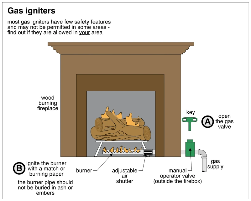 1095
1095Gas igniters
· p. 191
The illustration shows a gas igniter burner beneath a grate supporting burning logs in a wood-burning fireplace. A gas supply pipe connects the burner to a key-operated manual valve outside the firebox, and an adjustable air shutter is shown at the burner inlet. Lettered annotations describe opening the gas valve and lighting the burner with a match or burning paper. A note states that the burner pipe should not be buried in ash or embers. Another warning notes that most gas igniters have few safety features and may not be permitted in some areas.
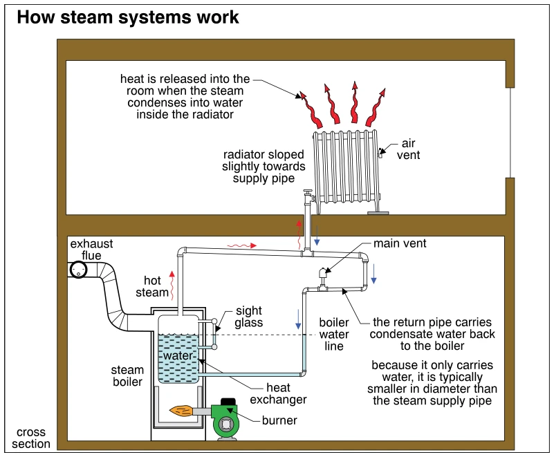 1096
1096How steam systems work
· p. 191
A cross-sectional schematic shows a steam boiler below a room radiator, connected by steam supply and condensate return piping. A burner heats the boiler water, and red arrows trace hot steam rising to the radiator, where condensation releases heat into the room. The radiator is sloped slightly toward its supply pipe and has an air vent at the opposite end. Blue arrows show condensate descending through the piping and returning to the boiler through a smaller-diameter return line. The drawing also identifies a main vent, sight glass, boiler water line, heat exchanger, and exhaust flue.
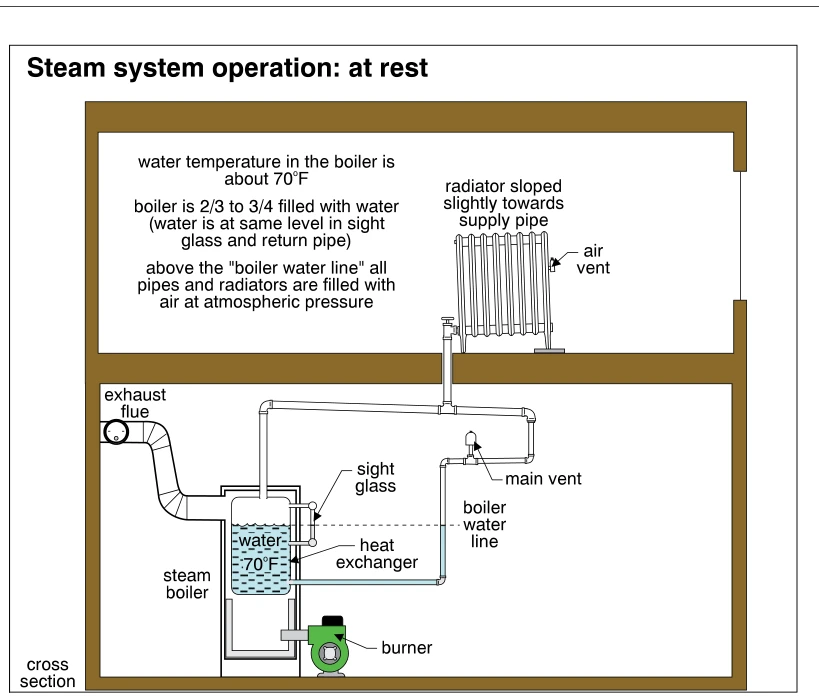 1097
1097Steam system operation: at rest
· p. 192
A building cross section shows a steam boiler below a radiator, connected by supply and return piping. At rest, the boiler is two-thirds to three-quarters filled with water at about 70°F, with the same water level in the boiler, sight glass, and return pipe. Above the indicated boiler water line, the pipes and radiator contain air at atmospheric pressure. The radiator slopes slightly toward its supply pipe and has an air vent at the opposite end; a main vent is shown on the piping near the boiler. The boiler assembly includes a burner, heat exchanger, sight glass, and exhaust flue.
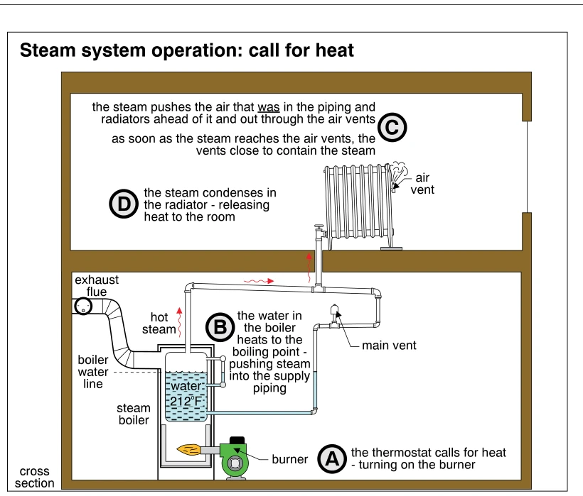 1098
1098Steam system operation: call for heat
· p. 192
A building cross section illustrates the call-for-heat sequence in a steam heating system, with a boiler and burner below a room radiator. The thermostat calls for heat and turns on the burner, heating boiler water to boiling and pushing steam into the supply piping. Steam displaces air through the main and radiator vents, which close when steam reaches them. Steam condenses in the radiator and releases heat to the room. The drawing also shows the boiler water line, exhaust flue, and a lower water-filled return connection to the boiler.
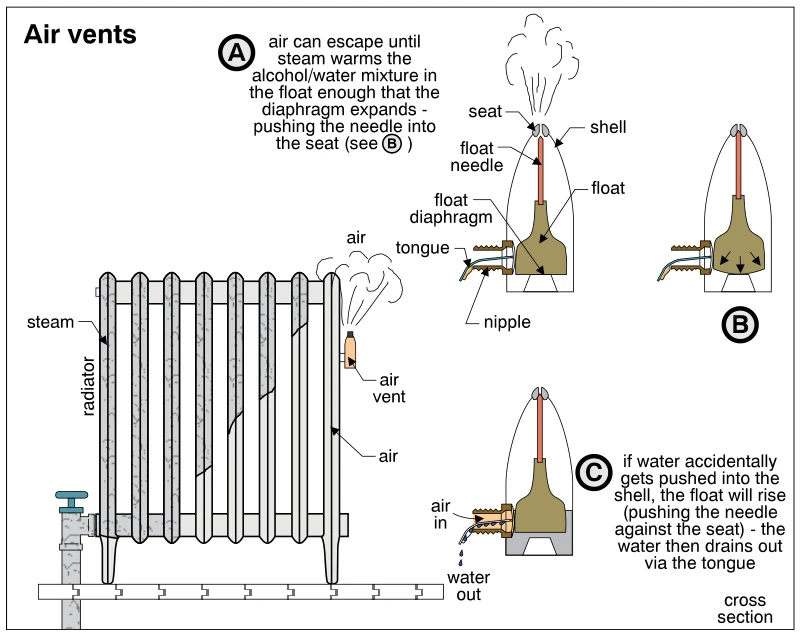 1099
1099Air vents
· p. 192
The illustration shows a steam radiator with a side-mounted air vent and three cross-sectional views explaining vent operation. Steam enters the radiator as displaced air escapes through the vent. In view A, air passes through the nipple into the shell and exits through the open seat; heating of the alcohol/water mixture in the float expands the diaphragm and pushes the needle into the seat, as shown in view B. View C shows that water entering the shell lifts the float and closes the needle against the seat, while water drains back out via the tongue.
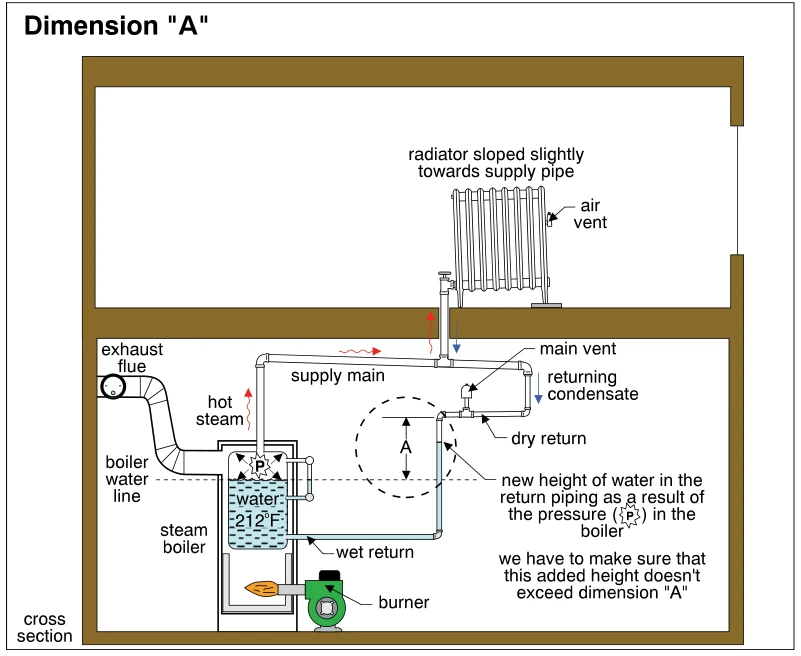 1100
1100Dimension "A"
· p. 192
A building cross section shows a steam boiler below a radiator, connected by a supply main and condensate return piping. Red arrows indicate rising hot steam, while blue arrows indicate returning condensate; the radiator is sloped slightly toward its supply pipe and has an air vent. The return assembly includes a main vent, a dry return above the boiler water line, and a wet return below it. Dimension "A" marks the vertical clearance between the boiler water line and the elevated return piping. An annotation explains that boiler pressure raises the water level in the return piping and that this rise must not exceed dimension "A".
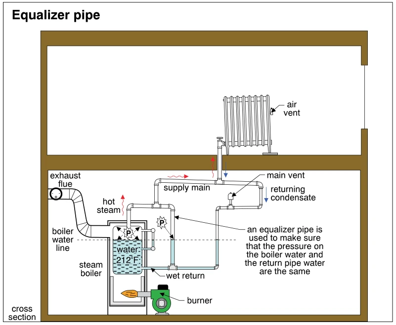 1101
1101Equalizer pipe
· p. 192
A cross-sectional schematic shows a steam boiler supplying a radiator on the floor above through a supply main. Red arrows indicate rising hot steam, while blue arrows indicate returning condensate flowing toward the wet return and boiler. An equalizer pipe connects the boiler's steam-side piping to the wet return, with an annotation explaining that it maintains equal pressure on the boiler water and return-pipe water. The boiler is shown with a burner, exhaust flue, water-level gauge, and dashed boiler water line; the radiator air vent and a main vent are also identified.
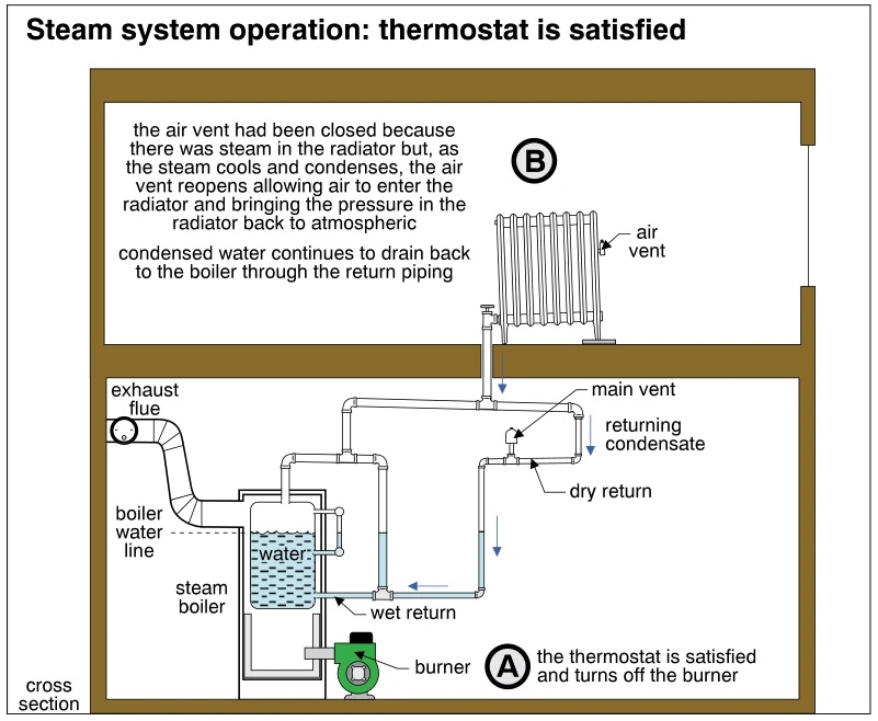 1102
1102Steam system operation: thermostat is satisfied
· p. 192
A building cross section shows a steam boiler and burner below a radiator, connected by steam and condensate return piping. At stage A, the satisfied thermostat turns off the burner. At stage B, steam in the radiator cools and condenses, and the radiator air vent reopens to admit air and restore atmospheric pressure. Blue arrows show condensate continuing to drain through the dry return and wet return to the boiler. The diagram also identifies the main vent, boiler water line, and exhaust flue.
Steam Heating Systems ·Common Steam Systemsp. 193
 1103
1103Hartford Loop
· p. 193
The cross-section schematic shows a steam boiler with a burner and exhaust flue supplying an upstairs radiator through a supply main. Red arrows indicate steam moving toward the radiator, while blue arrows indicate condensate returning through the dry return and descending return piping. An air vent is shown on the radiator and a main vent on the return piping. A dashed circle highlights the Hartford Loop connection near the boiler water line. The annotation explains that this arrangement prevents boiler water from draining out if the wet return piping upstream of the loop leaks.
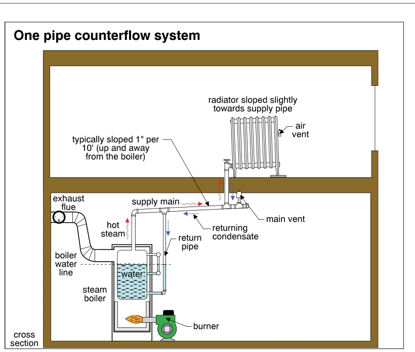 1104
1104One pipe counterflow system
· p. 193
A building cross section depicts a one-pipe counterflow steam heating system with a boiler below a radiator. Red arrows show steam traveling through the supply main toward the radiator, while blue arrows show condensate returning in the opposite direction through the same piping before descending through a return pipe to the boiler. The supply main is annotated as typically sloped 1 inch per 10 feet up and away from the boiler, and the radiator is sloped slightly toward its supply pipe. A radiator air vent and a main vent are shown, along with the boiler water line, burner, and exhaust flue.
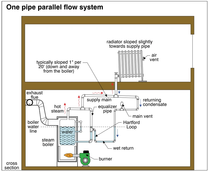 1105
1105One pipe parallel flow system
· p. 193
A building cross section shows a one-pipe parallel-flow steam heating system with a boiler below a radiator. Red arrows indicate steam rising from the boiler and traveling along the supply main to the radiator, while blue arrows show condensate returning through the piping. The supply main is labeled as sloping down and away from the boiler, typically 1 inch per 20 feet, and the radiator slopes slightly toward its supply pipe. The radiator has an air vent, and a main vent is shown on the return-side piping. The wet return connects back to the boiler through a Hartford Loop beside the equalizer pipe, with the boiler water line indicated by a dashed line.
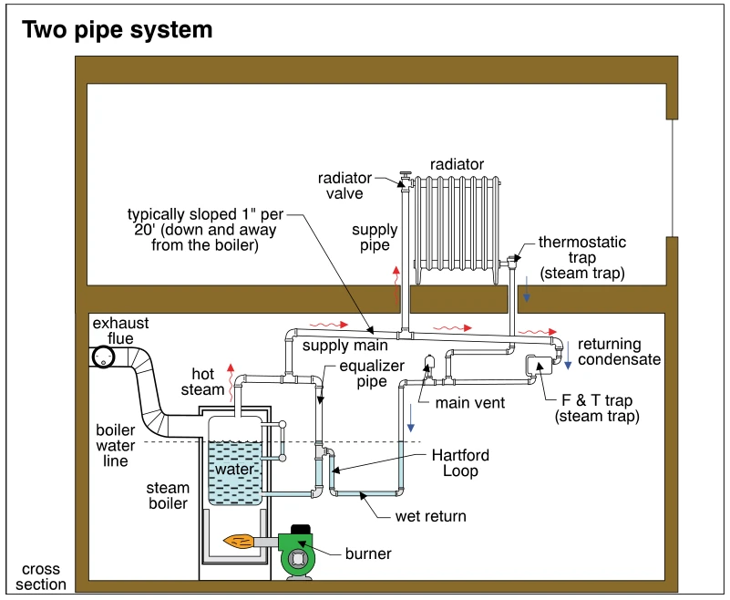 1106
1106Two pipe system
· p. 193
A building cross section illustrates a two-pipe steam heating system with a boiler below a radiator. Red arrows show steam traveling from the boiler through the supply main and up a separate supply pipe to the radiator valve. Condensate leaves the radiator through a thermostatic steam trap and returns through separate piping, with blue arrows indicating downward flow. The diagram also identifies an F & T steam trap, main vent, equalizer pipe, wet return, and Hartford Loop near the boiler. The supply main is annotated as typically sloped 1 inch per 20 feet down and away from the boiler, and a dashed line marks the boiler water level.
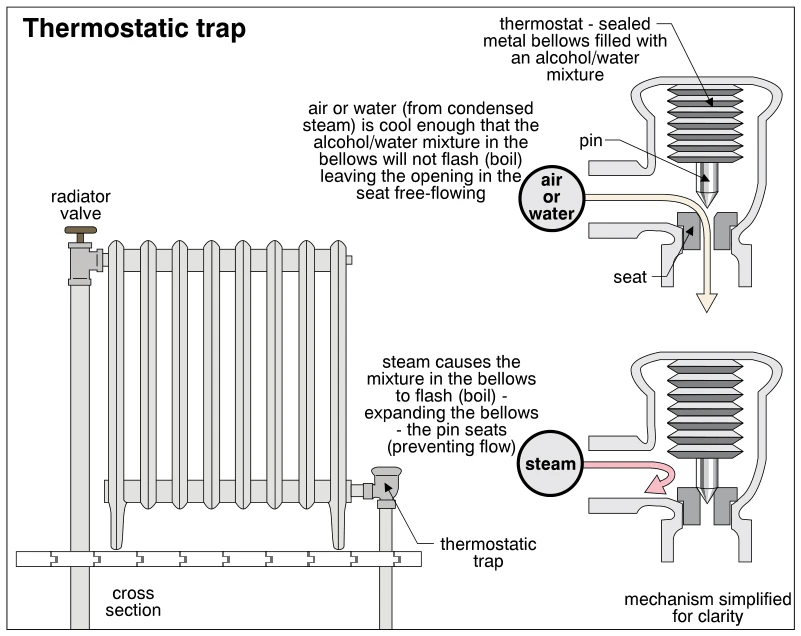 1107
1107Thermostatic trap
· p. 193
The illustration shows a steam radiator with a radiator valve at one end and a thermostatic trap at the opposite lower connection, with piping extending below a floor cross section. Two simplified trap sections explain its temperature-responsive operation. With cooler air or condensate present, the sealed alcohol/water-filled metal bellows remains contracted, holding the pin above the seat and allowing discharge. When steam reaches the trap, the mixture in the bellows boils and expands the bellows, pushing the pin onto the seat to prevent flow.
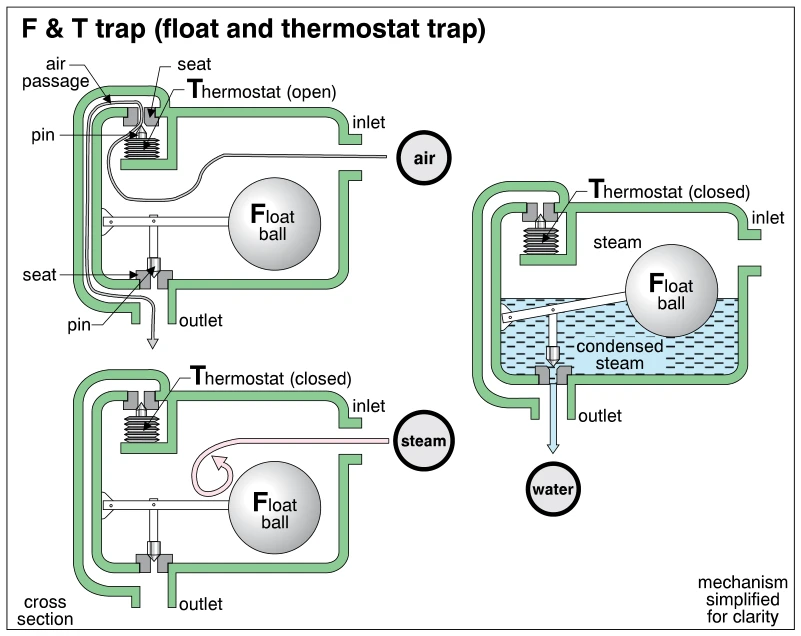 1108
1108F & T trap (float and thermostat trap)
· p. 193
Three simplified cross sections illustrate the operation of a float and thermostat trap in a steam-heating system. In the upper-left view, the thermostat is open, allowing air to pass through the air passage toward the outlet. In the lower-left view, steam enters and the thermostat is closed, while the float remains low and the condensate outlet valve is seated. In the right-hand view, accumulated condensed steam raises the float ball and its linkage, opening the lower valve so water can drain through the outlet while the thermostat remains closed.
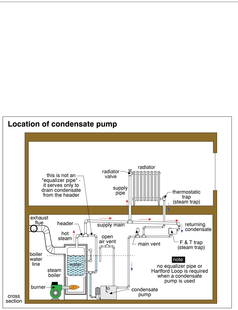 1109
1109Location of condensate pump
· p. 194
A building cross section shows a steam boiler below a radiator, with a condensate pump located near the basement floor beside the boiler. Red arrows trace steam from the boiler header through the supply main and up to the radiator, while blue arrows indicate condensate returning toward the pump. A thermostatic steam trap serves the radiator outlet, and an F & T steam trap is shown at the end of the supply main. The return piping includes a main vent, and the pump has an open air vent and a discharge connection back to the boiler. An annotation distinguishes the header condensate drain from an equalizer pipe, and a note states that no equalizer pipe or Hartford Loop is required when a condensate pump is used.
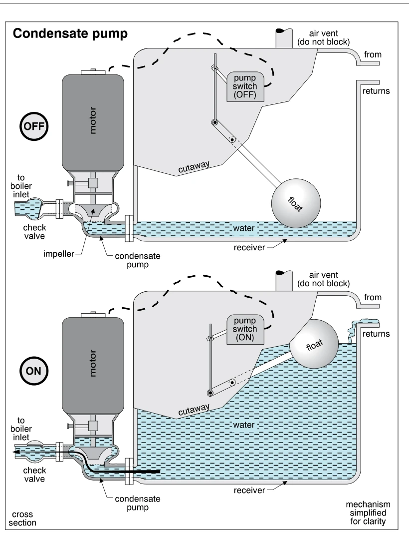 1110
1110Condensate pump
· p. 194
Two cutaway cross sections illustrate the off and on operating states of a steam-heating condensate pump assembly. Condensate enters a vented receiver from the return piping, and a float and linkage operate the pump switch according to the water level. In the upper view, the low water level leaves the float lowered and the pump switched off. In the lower view, accumulated water raises the float and switches on the motor-driven pump; arrows show water moving from the receiver through the pump and check valve toward the boiler inlet. Both views identify an air vent that must not be blocked, and the mechanism is simplified for clarity.
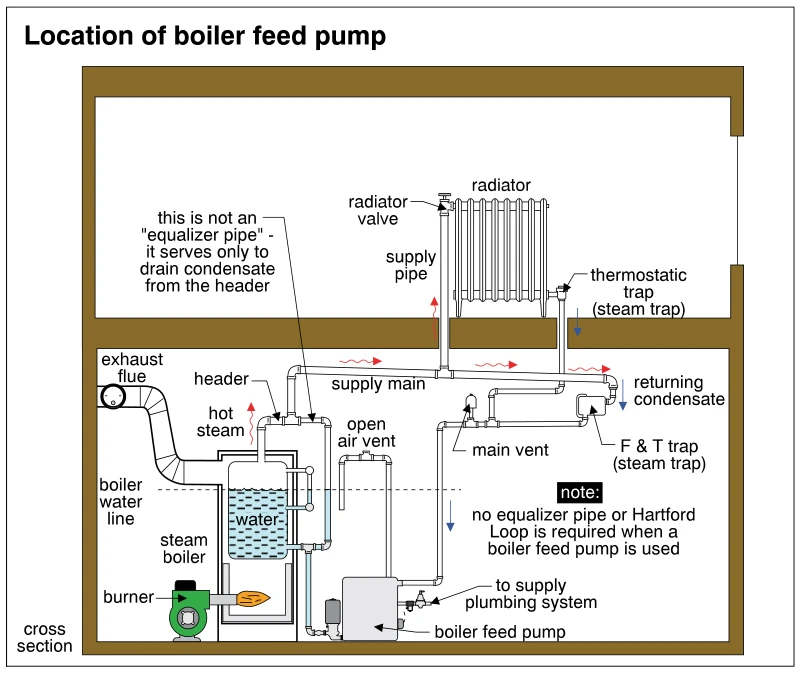 1112
1112Location of boiler feed pump
· p. 194
A building cross section shows a steam boiler and boiler feed pump below a radiator. Red arrows trace steam from the boiler header through the supply main and up the radiator supply pipe, while blue arrows indicate returning condensate. The radiator outlet has a thermostatic steam trap, and the end of the supply main has an F & T steam trap connected to the return piping. The feed pump receives condensate through vented return piping and connects back to the boiler, with a separate connection labeled to the supply plumbing system. An annotation distinguishes the header condensate drain from an equalizer pipe, and a note states that no equalizer pipe or Hartford Loop is required when a boiler feed pump is used.
 1113
1113Boiler feed pump
· p. 194
A cross section shows a steam-heating boiler feed pump drawing water from a receiver and discharging it through a check valve to the boiler inlet. Condensate enters from the returns near the top of the receiver, which has an air vent marked not to be blocked. A motor drives the feed pump, and an annotation states that the boiler's pump and low-water control governs its operation. An automatic water feeder uses a float switch, solenoid valve, and pressure-reducing valve marked 12 PSI to admit makeup water from the house supply and keep the receiver one-quarter filled. The receiver is identified as much larger than a condensate-pump receiver, and a note identifies a simpler ballcock valve as an alternative makeup-water control.
Steam Heating Systems ·Steam Controlsp. 195
 1114
1114Location of low water cut-out
· p. 195
The illustration shows a cross section of a steam heating system with a boiler and burner below a radiator. Arrows trace steam along the supply main to the radiator and condensate through return piping to the boiler. The equalizer pipe, Hartford Loop, wet return, main vent, and F & T steam trap are identified. An enlarged inset shows the low water cut-out beside the water level gauge at the boiler water line, with a switch connection to the boiler. The inset also identifies an automatic water feeder connected to the house supply plumbing and a blowdown valve beneath the control assembly.
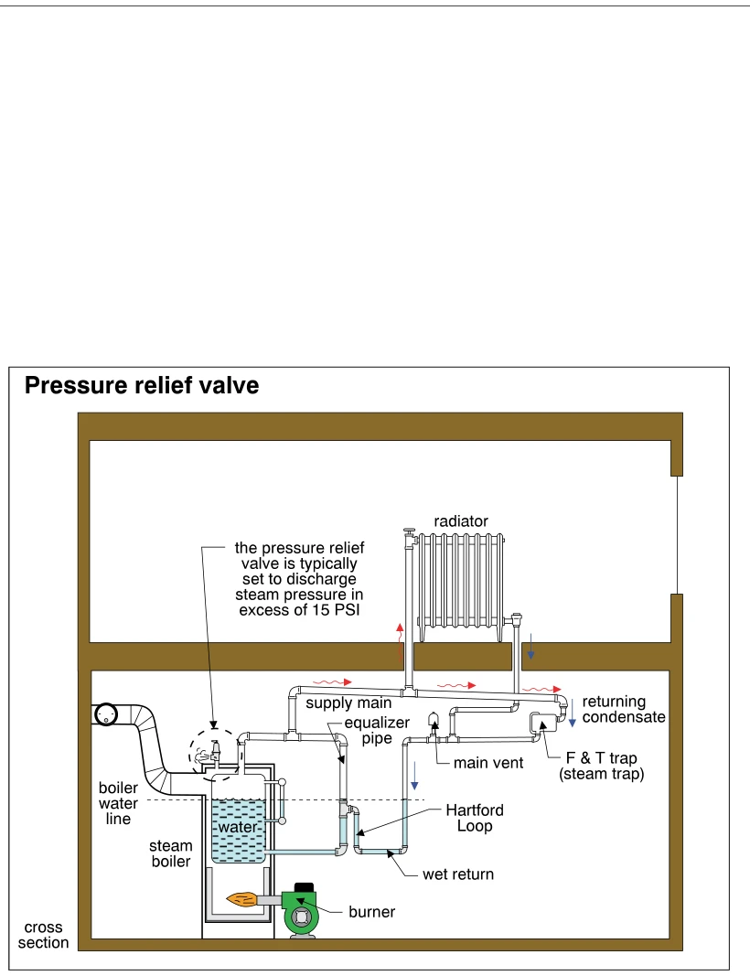 1115
1115Pressure relief valve
· p. 195
The illustration shows a building cross section with a steam boiler below a radiator, connected by a steam supply main and condensate return piping. Red arrows indicate steam movement toward the radiator and along the supply main, while blue arrows indicate returning condensate. The return arrangement includes an F & T steam trap, main vent, wet return, equalizer pipe, and Hartford Loop near the boiler. A callout identifies the boiler pressure relief valve and states that it is typically set to discharge steam pressure in excess of 15 PSI. The boiler cutaway shows the water level and burner beneath the water-containing section.
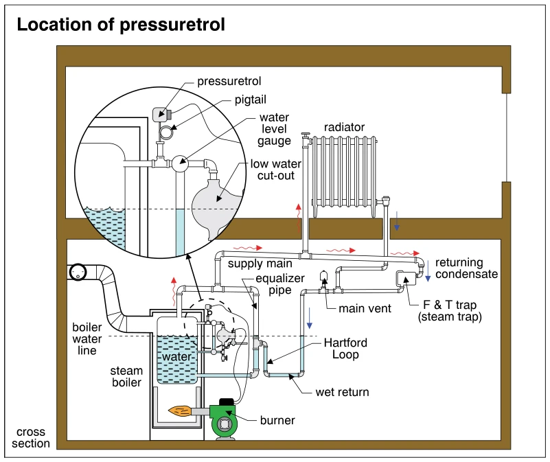 1116
1116Location of pressuretrol
· p. 195
The illustration shows a cross section of a steam-heating system with a basement boiler supplying an upper-floor radiator. Red arrows indicate steam flow through the supply piping, while blue arrows indicate condensate returning toward the boiler. A magnified detail identifies the pressuretrol mounted above a pigtail, alongside the water level gauge and low water cut-out. The piping diagram also identifies the equalizer pipe, Hartford Loop, wet return, main vent, and F & T steam trap. The boiler water line and burner are shown to establish the relationship between the boiler and its controls and return piping.
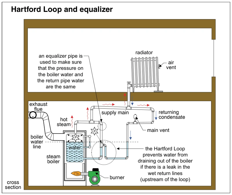 1117
1117Hartford Loop and equalizer
· p. 195
A building cross section shows a steam boiler supplying an upper-floor radiator through a supply main. Red arrows indicate steam flow, while blue arrows trace returning condensate toward the boiler through the return piping. An equalizer connects the steam piping to the boiler return connection to equalize pressure on the boiler water and return-pipe water. The Hartford Loop is highlighted near the boiler water line, illustrating how it prevents boiler water from draining away if an upstream wet return leaks. The drawing also identifies the radiator air vent, main vent, burner, and exhaust flue.
Steam Heating Systems ·Components and Problemsp. 196
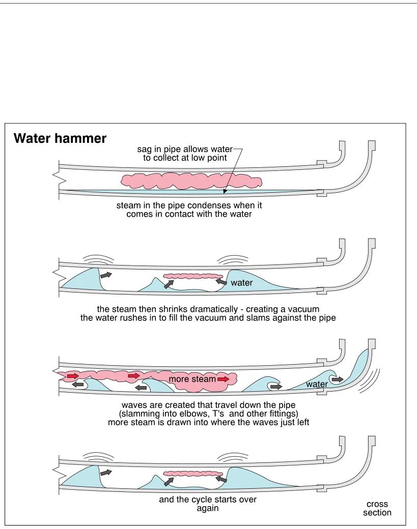 1118
1118Water hammer
· p. 196
Four sequential cross sections illustrate water hammer in a sagging steam-heating pipe with an elbow at the right end. Water collects at the low point, where contact with steam causes the steam to condense. The resulting volume reduction creates a vacuum, drawing water inward and causing it to slam against the pipe. Waves then travel along the pipe and strike elbows and other fittings as more steam enters the spaces they leave behind. The final panel shows the cycle repeating.
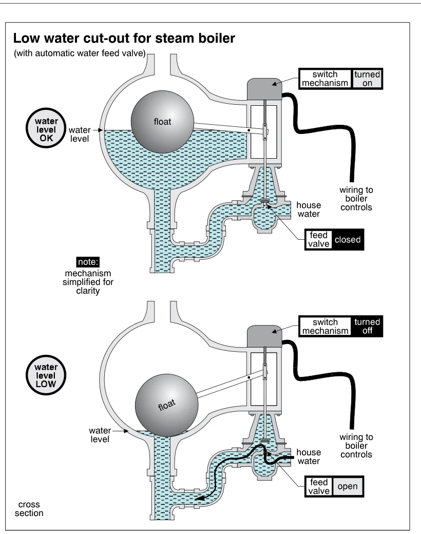 1119
1119Low water cut-out for steam boiler
· p. 196
Two cross-sectional diagrams show a float-operated low water cut-out with an automatic water feed valve for a steam boiler. In the upper diagram, the normal water level supports the float, the switch mechanism is turned on, and the feed valve is closed. In the lower diagram, the reduced water level lowers the float, turns the switch mechanism off, and opens the feed valve. Arrows show house water entering through the open valve and flowing toward the float chamber connection. Both diagrams show mechanical linkages between the float, switch, and feed valve, along with wiring to the boiler controls.
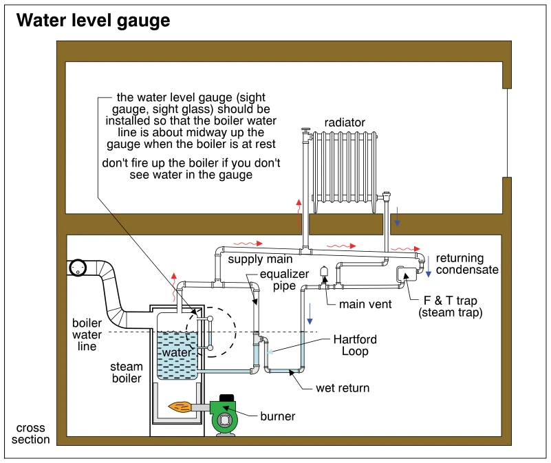 1120
1120Water level gauge
· p. 196
A building cross section shows a steam boiler connected to a radiator by a supply main and condensate-return piping. A sight glass mounted beside the boiler indicates the water level, with a dashed line marking the boiler water line. The annotation specifies that the resting boiler water line should be about midway up the gauge and warns against firing the boiler when no water is visible in the gauge. The piping diagram identifies an equalizer pipe, Hartford Loop, wet return, main vent, and F & T steam trap, with arrows indicating steam and condensate flow.
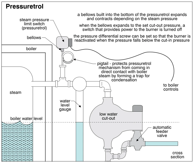 1121
1121Pressuretrol
· p. 196
This cross-sectional illustration shows a steam boiler with a pressuretrol, pigtail connection, water level gauge, low water cut-out, and automatic feeder valve. The pressuretrol connects to the boiler through a looped pigtail that traps condensation to protect the control mechanism from direct steam contact. Annotations explain that steam pressure expands the bellows, opening a switch to shut off burner power at the cut-out pressure; the differential adjustment determines when the burner restarts as pressure falls. The gauge water level aligns with the indicated boiler water level, and adjacent piping connects the low water cut-out and automatic feeder valve. No defective condition is depicted.
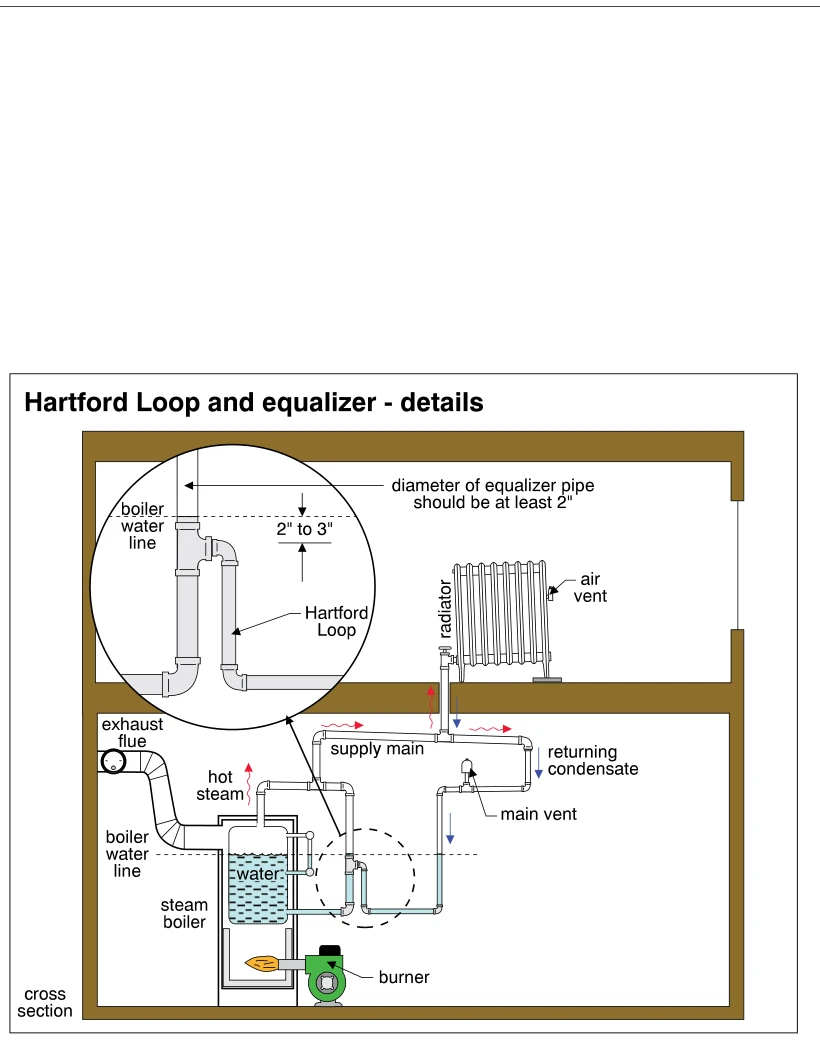 1122
1122Hartford Loop and equalizer - details
· p. 197
The illustration shows a cross section of a steam-heating system with a burner-fired boiler, exhaust flue, supply main, radiator, and condensate return piping. Red arrows indicate steam flow toward the radiator, while blue arrows indicate returning condensate flowing toward the boiler. An enlarged detail shows the Hartford Loop connection to the equalizer, positioned 2 to 3 inches below the boiler water line. The equalizer pipe is specified as at least 2 inches in diameter. Air vents are shown at the radiator and on the return end of the main.
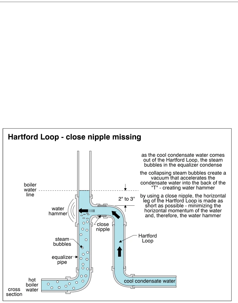 1123
1123Hartford Loop - close nipple missing
· p. 197
The cross-sectional drawing shows a steam-heating Hartford Loop joining an equalizer pipe below the boiler water line, with a indicated separation of 2 to 3 inches. Arrows show cool condensate rising through the loop and flowing horizontally into the equalizer, which contains hot boiler water and steam bubbles. The annotations explain that condensing steam bubbles create a vacuum that accelerates condensate into the back of the tee, causing water hammer. Although the title identifies a missing close nipple as the problem, the drawing labels the close-nipple connection and explains how shortening this horizontal leg reduces water momentum and water hammer.
 1124
1124Air vents
· p. 197
The illustration shows steam entering a sectional radiator and displacing air through a side-mounted air vent. Enlarged cross sections show the vent shell, float, diaphragm, needle, seat, connecting nipple, and drainage tongue. In condition A, air escapes until steam heats the alcohol/water mixture in the float, expanding the diaphragm and pushing the needle into the seat, as shown in B. Condition C shows water entering the shell and raising the float to close the needle against the seat; water then drains out via the tongue.
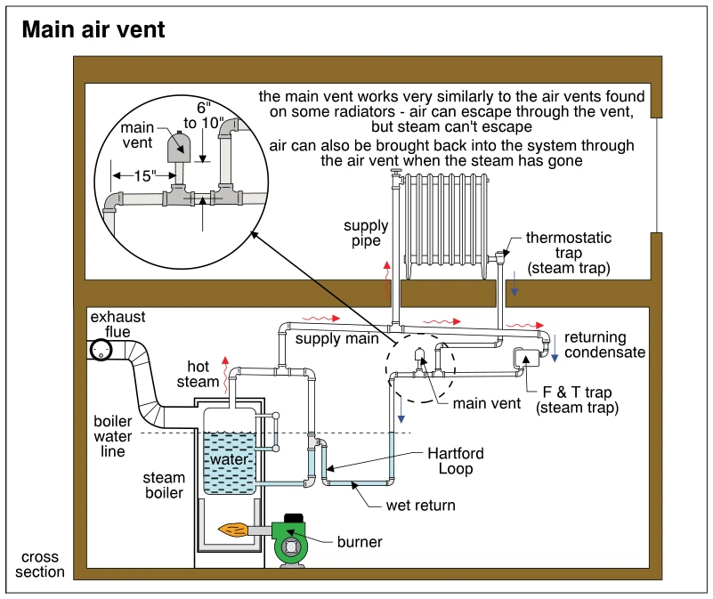 1125
1125Main air vent
· p. 197
A building cross section diagrams a steam-heating system with a burner-fired boiler, supply main, radiator, steam traps, and condensate return piping. Red arrows trace steam toward the radiator and main-end trap, while blue arrows indicate condensate returning toward the boiler through the wet return and Hartford Loop. A main air vent is shown on the return piping, with a magnified inset indicating a 6- to 10-inch vertical dimension and a 15-inch horizontal dimension near the vent assembly. Annotations explain that the main vent releases air but not steam and can admit air again after the steam has gone. The boiler water line and water level are shown relative to the return connections.
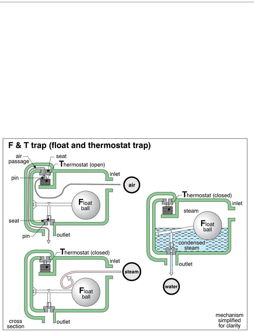 1126
1126F & T trap (float and thermostat trap)
· p. 198
Three simplified cross sections illustrate the operating stages of a float and thermostat steam trap. In the first, the thermostat is open, allowing air to pass through the air passage toward the outlet while the float ball is low. In the second, incoming steam closes the thermostat, and the low float keeps the condensate outlet valve closed. In the third, accumulated condensed steam raises the float ball and its linked valve pin, allowing water to discharge through the outlet while the thermostat remains closed.
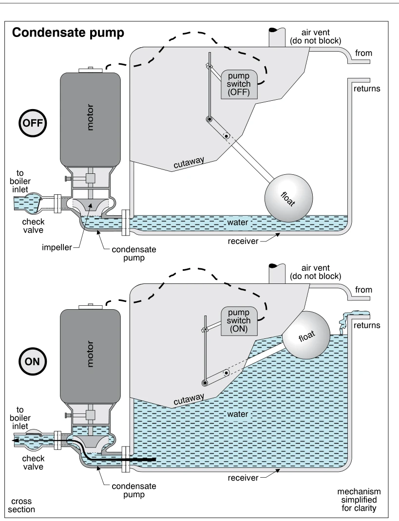 1127
1127Condensate pump
· p. 198
Two cutaway views illustrate the off and on operating states of a condensate pump in a steam-heating system. Condensate enters a vented receiver from the return piping, and a float linked to the pump switch responds to the water level. In the upper view, the low water level leaves the float down and the motor off; in the lower view, the higher water level raises the float and switches the motor on. The motor-driven impeller pumps water through a check valve toward the boiler inlet, as shown by flow arrows in the lower view. Both views identify an air vent that must not be blocked, and the mechanism is noted as simplified for clarity.
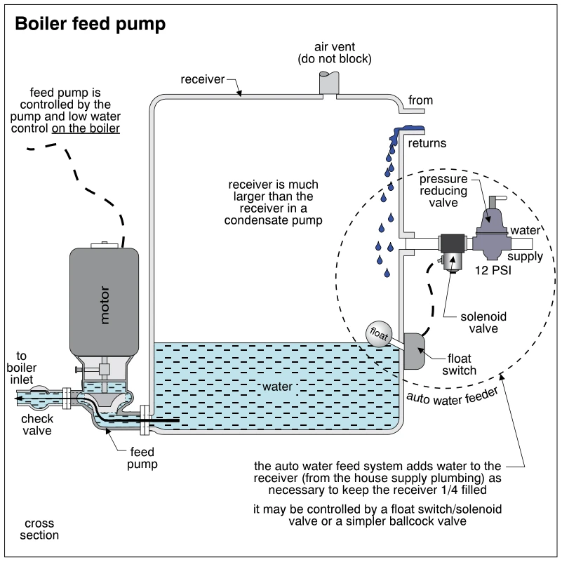 1128
1128Boiler feed pump
· p. 198
The cross section shows a steam-heating boiler feed pump with a vented receiver collecting water from the system returns. A motor-driven pump draws water from the bottom of the receiver and sends it through a check valve to the boiler inlet, under control of the boiler's pump and low-water control. An automatic water feeder supplies makeup water through a pressure-reducing valve marked 12 PSI and a solenoid valve operated by a receiver float switch. The annotations specify keeping the receiver one-quarter filled, leaving the air vent unobstructed, and using a receiver much larger than that of a condensate pump. A ballcock valve is noted as an alternative makeup-water control.
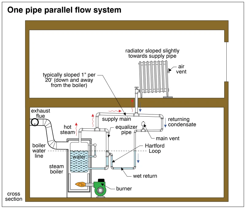 1129
1129One pipe parallel flow system
· p. 198
A building cross section illustrates a one-pipe parallel-flow steam heating system with a boiler below a radiator. Red arrows show steam rising from the boiler through the supply main to the radiator, while blue arrows show condensate draining back through the piping. The radiator slopes slightly toward its single supply connection, and the supply main slopes down and away from the boiler, typically 1 inch per 20 feet. The return arrangement includes a main vent, wet return, equalizer pipe, and Hartford Loop, shown relative to the boiler water line. A radiator air vent, burner, and exhaust flue are also identified.
Electric Heating Systems ·Introductionp. 199
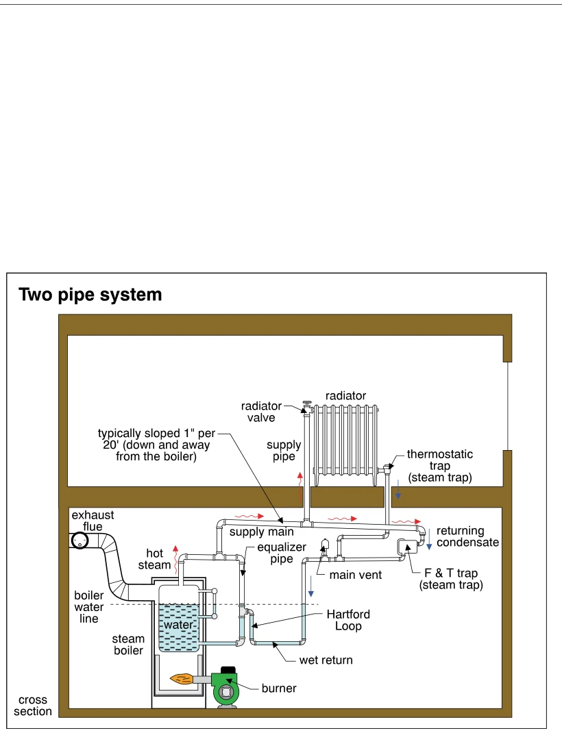 1130
1130Two pipe system
· p. 199
This building cross section illustrates a two-pipe steam heating system with a basement boiler supplying an upper-floor radiator. Red arrows show steam moving through the supply main and supply pipe to the radiator valve, while blue arrows indicate returning condensate through separate return piping. The radiator outlet has a thermostatic steam trap, and the main piping includes an F & T steam trap and a main vent. An equalizer pipe, Hartford Loop, and wet return connect near the boiler, with the boiler water line marked for reference. The supply main is annotated as typically sloped 1 inch per 20 feet down and away from the boiler; the burner and exhaust flue are also shown.
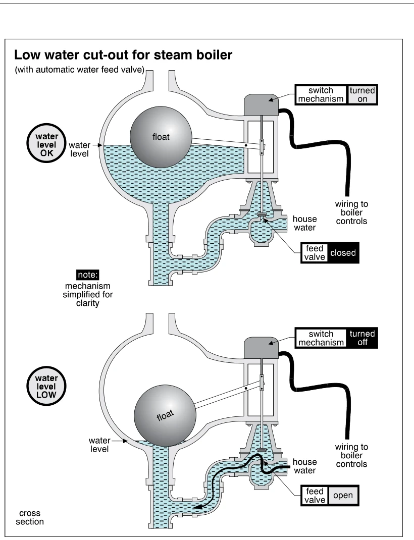 1131
1131Low water cut-out for steam boiler
· p. 199
Two cross sections illustrate a float-operated low-water cut-out with an automatic water feed valve for a steam boiler. In the upper view, the normal water level holds the float up, the switch mechanism is turned on, and the feed valve is closed. In the lower view, the low water level allows the float to drop, turning the switch mechanism off and opening the feed valve. Arrows show house water flowing through the open valve into the float chamber connection. Both views show wiring from the switch mechanism to the boiler controls, and a note states that the mechanism is simplified for clarity.
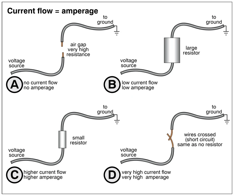 1132
1132Current flow = amperage
· p. 199
Four schematic examples illustrate the relationship between electrical resistance and current flow, or amperage, along a path from a voltage source to ground. Example A shows an air gap with very high resistance and no current flow. Example B shows a large resistor with low current flow, while example C shows a small resistor with higher current flow. Example D shows crossed exposed wires forming a short circuit, labeled as equivalent to no resistor and producing very high amperage.
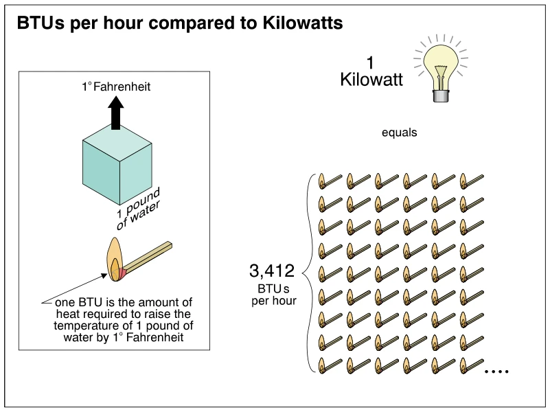 1133
1133BTUs per hour compared to Kilowatts
· p. 199
This illustration explains the relationship between British thermal units per hour and kilowatts as measures of heating rate. An inset uses a burning match, a cube representing one pound of water, and an upward arrow to define one BTU as the heat required to raise that water's temperature by 1° Fahrenheit. On the right, a light bulb represents one kilowatt, equated to 3,412 BTUs per hour represented by a grouped array of burning matches. The diagram is a unit-conversion reference rather than a depiction of an installed heating assembly.
Electric Heating Systems ·Space Heatersp. 200
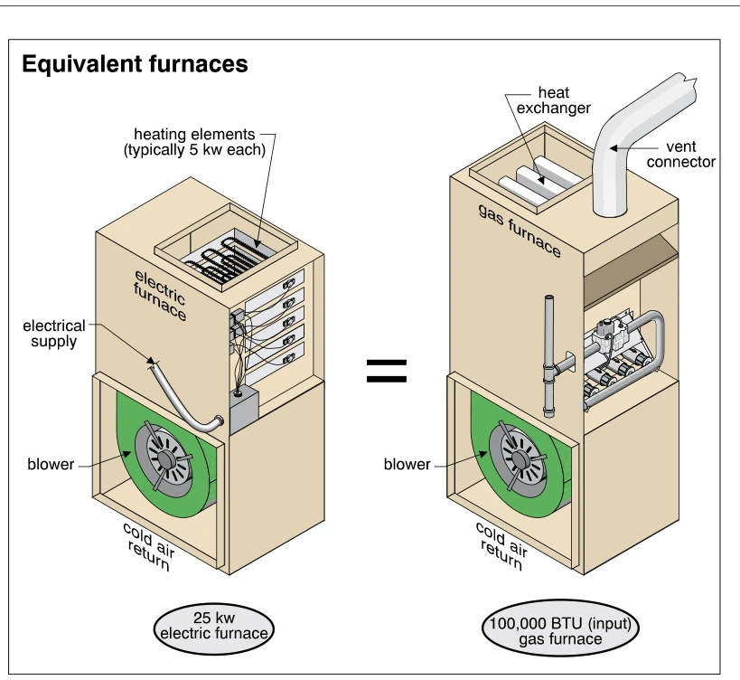 1134
1134Equivalent furnaces
· p. 200
The illustration compares cutaway views of an electric forced-air furnace and a gas forced-air furnace, joined by an equals sign. The electric furnace contains resistance heating elements labeled as typically 5 kw each, with an electrical supply entering the cabinet. The gas furnace shows a burner assembly, heat exchanger, and vent connector. Both furnaces have a blower in the lower compartment and a cold air return. The diagram presents a 25 kw electric furnace as equivalent to a 100,000 BTU input gas furnace; no defects are depicted.
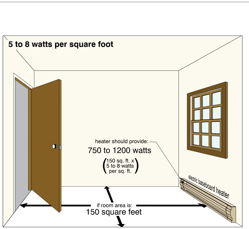 1135
11355 to 8 watts per square foot
· p. 200
The illustration shows a room with an open door, a window, and an electric baseboard heater along the bottom of the right wall. Arrows across the floor accompany a stated room area of 150 square feet. The drawing uses a heating allowance of 5 to 8 watts per square foot to calculate a heater output of 750 to 1200 watts. A leader connects the calculated heating requirement to the baseboard heater.
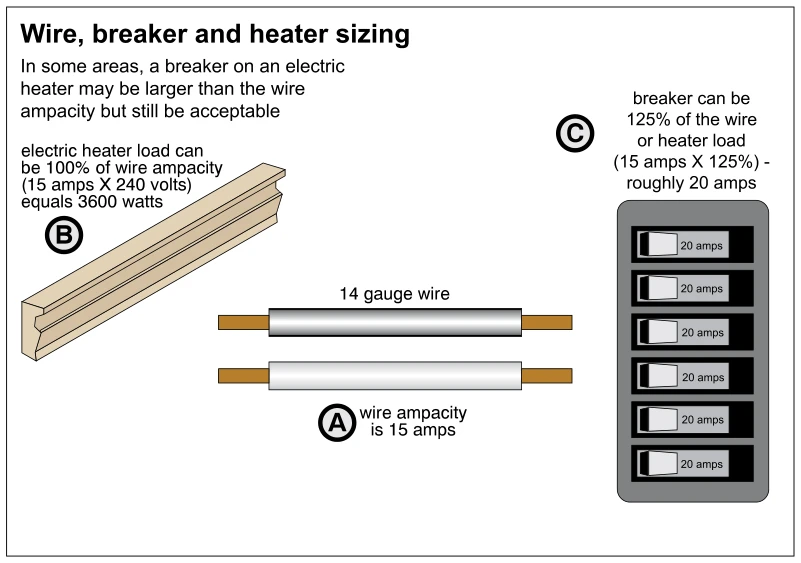 1136
1136Wire, breaker and heater sizing
· p. 200
The illustration compares the sizing of an electric baseboard heater, two insulated conductors, and circuit breakers. The conductors are labeled 14 gauge with a wire ampacity of 15 amps. The heater annotation describes a load equal to 100% of wire ampacity, calculated as 15 amps at 240 volts, or 3600 watts. A panel containing six breakers labeled 20 amps illustrates breaker sizing at approximately 125% of the wire or heater load. The figure explicitly qualifies this arrangement as acceptable in some areas rather than presenting it as a universal sizing rule.
 1137
1137Floor mounted electric heaters
· p. 200
The illustration shows a floor-mounted electric heater with a rectangular grille set flush into the floor beside a sliding glass door. A red upward arrow indicates heated air rising from the grille along the glazing. Curtains hang beside the door. The annotations recommend locating these heaters below windows and sliding glass doors and explain that they may operate with or without fans and are typically controlled by wall-mounted thermostats.
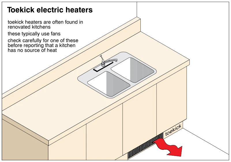 1138
1138Toekick electric heaters
· p. 200
The illustration shows an electric heater recessed into the toekick beneath kitchen base cabinets with a countertop and double-bowl sink. A rectangular grille occupies part of the recessed cabinet base, and a red arrow indicates heated air discharging into the room. The annotations explain that these heaters typically use fans and are often found in renovated kitchens. Inspectors are advised to check for a toekick heater before reporting that a kitchen has no heat source.
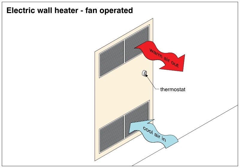 1139
1139Electric wall heater - fan operated
· p. 200
The illustration shows a fan-operated electric wall heater with upper and lower louvered grilles. A blue arrow indicates cool room air entering the lower grille, and a red arrow indicates warm air leaving the upper grille. A thermostat knob is located on the heater face between the grilles. The internal fan and heating elements are not shown, and no defects or improper installation conditions are depicted.
 1140
1140Best location for electric heaters
· p. 201
The illustration shows a room with an electric baseboard heater installed at floor level on an outside wall beneath a window. A downward blue arrow indicates cool air descending below the window, while an upward red arrow indicates hot air rising from the heater. The annotation identifies floor-level areas along outside walls, particularly beneath windows, as the coolest spots in a room and the preferred locations for electric heaters. An open door is shown on the opposite side of the room.
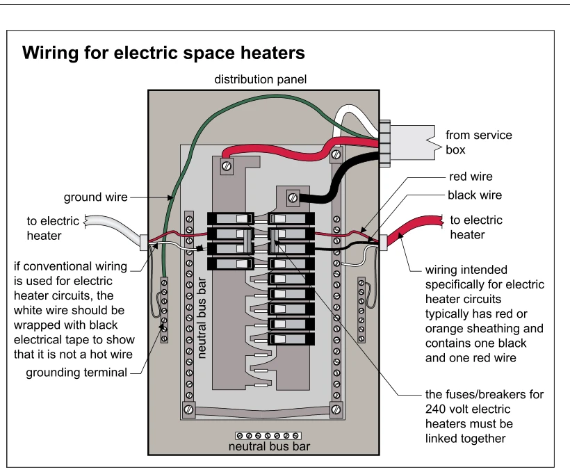 1141
1141Wiring for electric space heaters
· p. 201
The illustration shows an open distribution panel supplied from a service box, with two outgoing circuits to electric space heaters. One circuit uses conventional cable with a white conductor marked with black tape; the other uses red-sheathed heater cable containing red and black conductors. Grounding terminals, neutral bus bars, and the incoming ground wire are identified within the panel. The drawing specifies that the fuses or breakers for 240-volt electric heaters must be linked together. The conventional-wiring annotation says the tape shows the white conductor is 'not a hot wire,' an apparent wording error in the printed illustration.
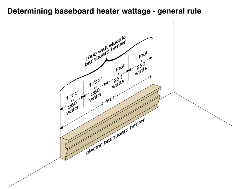 1142
1142Determining baseboard heater wattage - general rule
· p. 201
The illustration shows an electric baseboard heater mounted along the bottom of a wall near a room corner. A dimension line identifies its length as 4 feet, subdivided into four 1-foot sections. Each section is labeled as equivalent to 250 watts, and a bracket identifies the entire heater as 1000 watts. The drawing presents a general rule for estimating electric baseboard heater wattage from length, rather than depicting a defect.
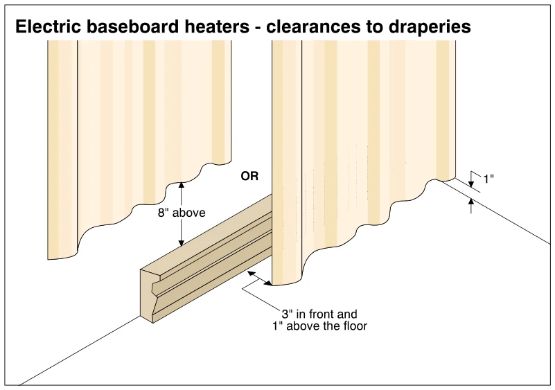 1143
1143Electric baseboard heaters - clearances to draperies
· p. 201
The illustration shows two alternative drapery clearances around an electric baseboard heater mounted at the base of a wall. On the left, the drapery hem terminates 8 inches above the heater. On the right, longer draperies hang 3 inches in front of the heater and terminate 1 inch above the floor. Dimension arrows identify the required separation between the fabric, heater, and floor.
Electric Heating Systems ·Electric Furnacesp. 202
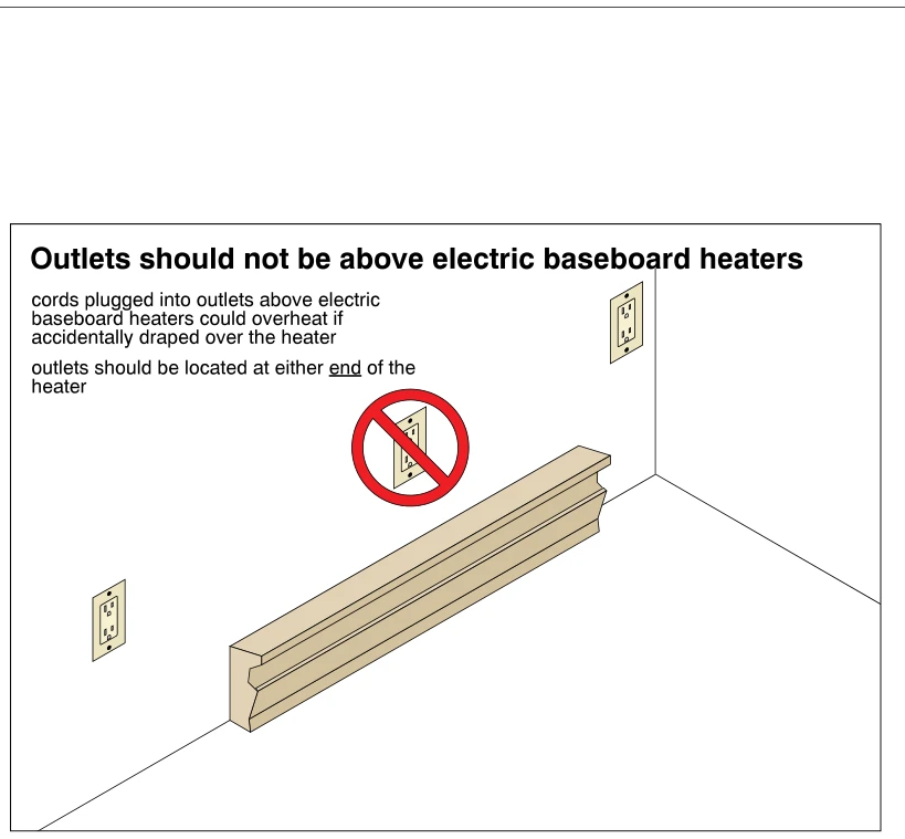 1144
1144Outlets should not be above electric baseboard heaters
· p. 202
The illustration shows an electric baseboard heater mounted along the bottom of an interior wall, with three duplex receptacles indicating possible outlet locations. The receptacle directly above the heater is marked with a red prohibition symbol. Receptacles beyond either end of the heater illustrate the recommended locations. The annotation explains that cords plugged into outlets above the heater could overheat if accidentally draped over it; no cord is shown.
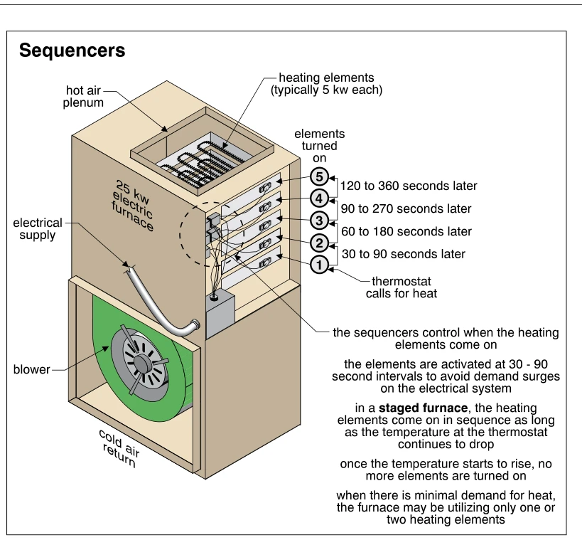 1145
1145Sequencers
· p. 202
A cutaway illustration of a 25 kW electric furnace shows a lower blower and cold-air return beneath an array of resistance heating elements and a hot-air plenum. Electrical supply conduit and internal wiring connect to the heating assembly and its sequencers. Five numbered heating stages illustrate the first element turning on when the thermostat calls for heat, with subsequent elements activated at cumulative delays of 30–90, 60–180, 90–270, and 120–360 seconds. The annotations explain that sequencers stagger element activation to avoid electrical demand surges. In a staged furnace, additional elements turn on while thermostat temperature continues to drop, but no additional elements turn on once temperature starts rising; minimal demand may require only one or two elements.
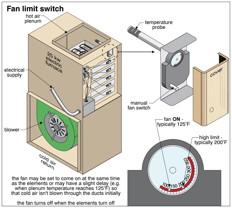 1146
1146Fan limit switch
· p. 202
The illustration shows a cutaway electric furnace with a blower in the lower compartment, electric heating elements above, and a hot air plenum at the top. An enlarged fan limit switch shows its temperature probe, adjustable dial, manual fan switch, and removable cover. A dial detail identifies a typical fan-on setting of 125°F and a typical high-limit setting of 200°F. The annotations explain that the fan may start with the heating elements or after a slight delay to avoid initially blowing cold air through the ducts, and that it turns off when the elements turn off.
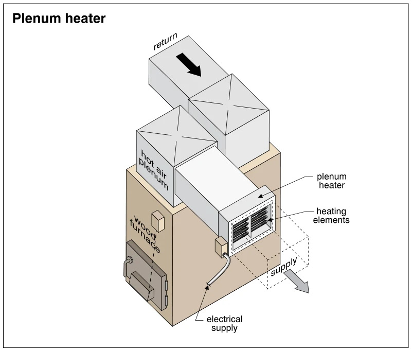 1147
1147Plenum heater
· p. 202
The illustration shows an electric plenum heater installed in the supply duct connected to the hot-air plenum of a wood furnace. An exposed face of the heater reveals banks of electric heating elements inside the duct opening. An electrical supply cable connects to a box on the side of the heater assembly. Arrows identify return air entering the furnace ductwork and supply air leaving through a dashed-outline duct extension downstream of the heater. No defects or improper installation practices are identified.
Electric Heating Systems ·Radiant Heatingp. 203
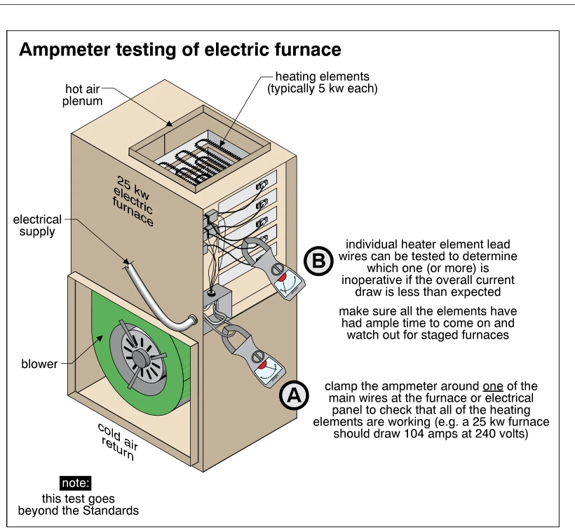 1148
1148Ampmeter testing of electric furnace
· p. 203
A cutaway electric furnace shows a blower above the cold air return, resistance heating elements at the top, and a hot air plenum. Two clamp-on ammeters illustrate testing the main supply conductor for total current draw and an individual heater element lead for element current draw. The annotation gives an expected draw of 104 amps at 240 volts for a 25 kw furnace and explains that individual leads can be tested to locate inoperative elements when total draw is low. It cautions that elements need time to energize, particularly in staged furnaces, and notes that this test goes beyond the Standards.
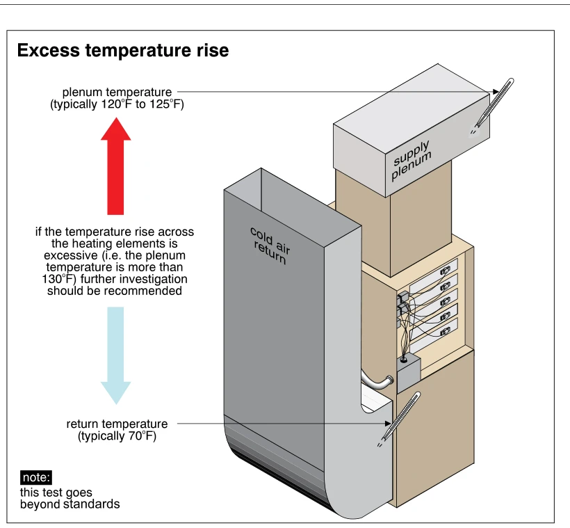 1149
1149Excess temperature rise
· p. 203
The illustration shows an electric forced-air furnace with a cold-air return duct and an overhead supply plenum. An open section of the furnace exposes a bank of heating elements and associated wiring. Thermometers indicate measurement locations at the return and supply plenum, labeled with typical temperatures of 70°F and 120°F to 125°F, respectively. The annotation recommends further investigation when temperature rise across the heating elements is excessive, identified here as a plenum temperature above 130°F. A note states that this test goes beyond standards.
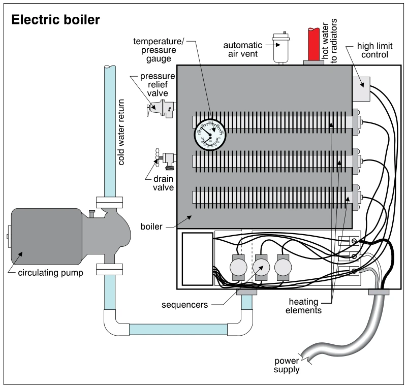 1150
1150Electric boiler
· p. 203
The illustration shows an electric boiler with three horizontal heating elements inside the boiler vessel. A circulating pump is installed on the cold-water return piping, which connects to the bottom of the boiler, while a top outlet carries hot water to radiators. A temperature/pressure gauge, pressure relief valve, drain valve, and automatic air vent are identified on the assembly. A high limit control and sequencers are connected by wiring to the heating elements, with the power supply entering the lower electrical compartment. This is an informational component diagram with no specific defect depicted.
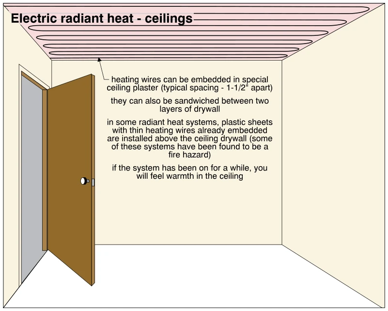 1151
1151Electric radiant heat - ceilings
· p. 203
The illustration shows a room with electric radiant heating wires arranged in closely spaced, back-and-forth runs across the ceiling. An arrow identifies wires that can be embedded in special ceiling plaster, with typical spacing of 1-1/2 inches. Annotations describe alternative installations between two layers of drywall or in plastic sheets above the ceiling drywall. The text warns that some plastic-sheet systems have been found to be a fire hazard and notes that the ceiling will feel warm after the system has operated for a while.
And Gas Fireplaces ·Wall Furnacesp. 204
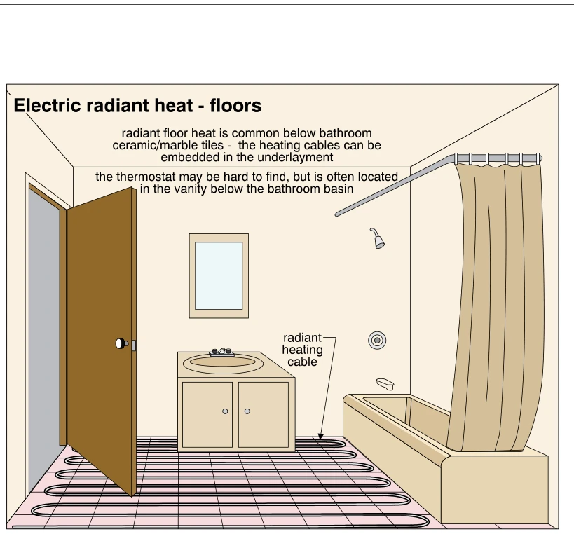 1152
1152Electric radiant heat - floors
· p. 204
The illustration depicts electric radiant floor heating in a bathroom containing a vanity, basin, and bathtub with a shower curtain. A heating cable follows a continuous serpentine pattern across the tiled floor area, shown exposed for illustration. An annotation explains that the cables can be embedded in the underlayment below ceramic or marble tiles. Another annotation notes that the thermostat may be difficult to find and is often located in the vanity below the basin. No installation defect is identified.
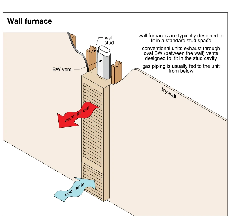 1153
1153Wall furnace
· p. 204
The illustration depicts a tall, narrow gas-fired wall furnace recessed into a drywall wall between wood studs. A cutaway above the furnace exposes an oval BW vent extending upward within the stud cavity. The lower grille admits cool room air, while the upper grille releases warm air, as indicated by colored arrows. Notes explain that these furnaces typically fit a standard stud space and that gas piping is usually supplied from below, although the piping itself is not shown. No installation defect is identified.
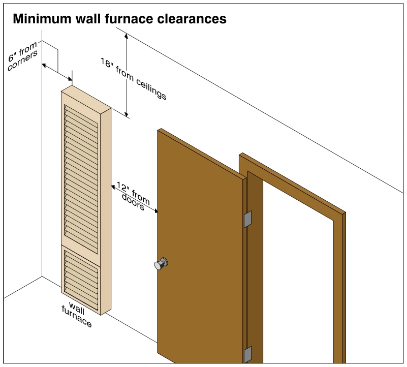 1154
1154Minimum wall furnace clearances
· p. 204
The illustration shows a tall, louvered wall furnace installed near an inside wall corner and an open hinged door. Dimension arrows indicate minimum clearances of 6 inches from corners, 18 inches from ceilings, and 12 inches from doors. The door clearance is illustrated between the side of the furnace and the nearby edge of the open door. The drawing presents clearance guidance rather than a defective installation.
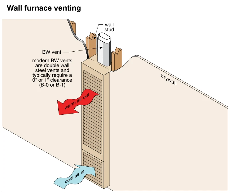 1155
1155Wall furnace venting
· p. 204
The illustration shows a wall furnace recessed into a drywall partition, with a cutaway exposing wood studs and a vertical BW vent above the unit. The narrow vent rises within the wall framing from the top of the furnace. Arrows indicate cool room air entering the lower grille and warm air leaving the upper grille. An annotation identifies modern BW vents as double-wall steel vents and states that they typically require 0-inch or 1-inch clearance, designated B-0 or B-1. No defect is explicitly depicted.
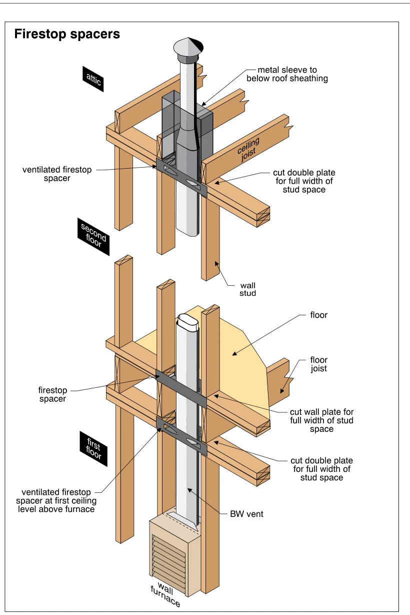 1156
1156Firestop spacers
· p. 205
The illustration shows a wall furnace with a BW vent rising within a wood-framed stud space through the first-floor ceiling, second floor, and attic. Ventilated firestop spacers are shown at the first ceiling above the furnace and at the attic ceiling penetration, with another firestop spacer at the intervening floor framing. Annotations direct that the double plates and wall plate be cut for the full width of the stud space at the vent passage. A metal sleeve surrounds the vent in the attic and is specified to extend to below the roof sheathing. The vent terminates above with a cap.
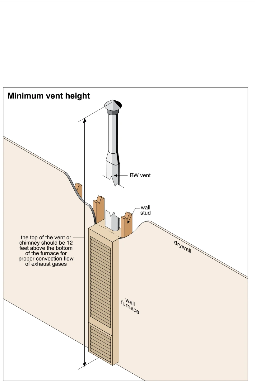 1157
1157Minimum vent height
· p. 205
The illustration shows a wall furnace installed between wood wall studs behind a cutaway drywall surface. A BW vent rises vertically from the furnace and terminates in a cap, with breaks in the drawing indicating an extended vent run. A vertical dimension arrow measures from the bottom of the furnace to the top of the vent. The annotation specifies a height of 12 feet for proper convection flow of exhaust gases.
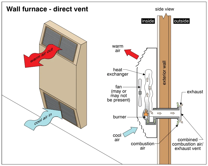 1158
1158Wall furnace - direct vent
· p. 205
The illustration shows a direct-vent wall furnace in perspective and in a side-view schematic at an exterior wall. Cool room air enters the lower grille, passes the heat exchanger, and exits as warm air through the upper grille. The schematic identifies the burner and a fan that may or may not be present. A combined combustion-air and exhaust vent passes horizontally through the exterior wall, supplying outdoor air to the burner and discharging exhaust outside. Arrows distinguish room-air circulation from the combustion-air and exhaust paths.
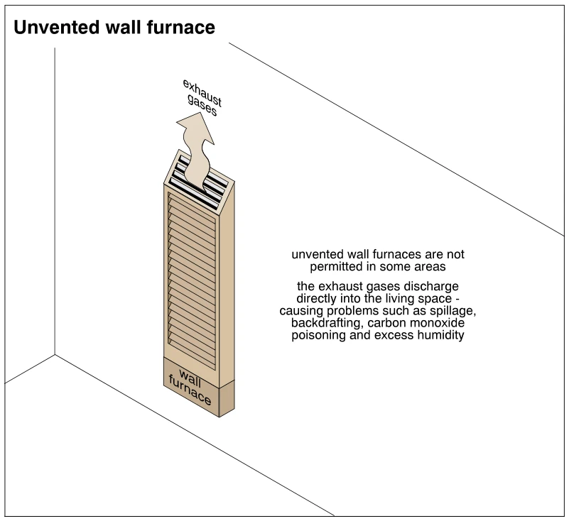 1159
1159Unvented wall furnace
· p. 205
The illustration shows a tall, narrow unvented wall furnace installed against an interior wall, with a louvered front and an outlet grille at the top. An upward arrow indicates exhaust gases discharging directly into the living space rather than through an exterior vent. The annotations warn that unvented wall furnaces are not permitted in some areas. They identify spillage, backdrafting, carbon monoxide poisoning, and excess humidity as associated problems.
And Gas Fireplaces ·Floor Furnacesp. 206
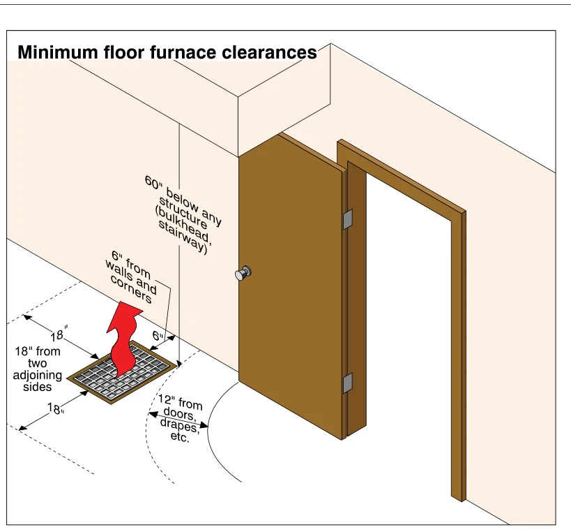 1160
1160Minimum floor furnace clearances
· p. 206
The illustration shows a floor furnace grille near a wall corner, an overhead bulkhead, and a swinging door. A red upward arrow indicates heat rising from the grille. Dimension arrows specify minimum clearances of 6 inches from walls and corners, 18 inches from two adjoining sides, and 60 inches below any structure such as a bulkhead or stairway. A door-swing arc illustrates the required 12-inch clearance from doors, drapes, and similar obstructions.
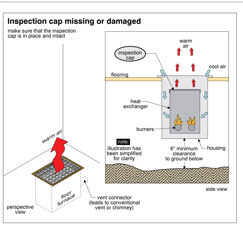 1161
1161Inspection cap missing or damaged
· p. 206
The illustration shows a gas-fired floor furnace in perspective and a simplified side section beneath the flooring. The section identifies burners within the heat exchanger, an inspection cap at its top, and an outer housing. Blue arrows show cool air descending around the heat exchanger, while red arrows show warm air rising into the room through the floor opening. A vent connector in the perspective view leads to a conventional vent or chimney. The annotations direct the inspector to verify that the inspection cap is present and intact and indicate a minimum 6-inch clearance between the housing and the ground below.
 1162
1162Room heaters - combustible clearances
· p. 206
The illustration compares combustible-clearance dimensions for a circulating-type gas room heater and a radiant gas room heater, each with a vent connector. The circulating heater is labeled with 12-inch clearances from the sides and back (noted as variable), 24 inches from the front, and 36 inches from the top. The radiant heater is labeled with 18-inch clearances from the sides and back (also variable), 36 inches from the front, and 36 inches from the top. Colored arrows show air entering the circulating heater below and heated air exiting above, while wavy arrows indicate heat radiating from the radiant heater. A note states that combustible clearances vary significantly by jurisdiction and advises checking with local authorities.
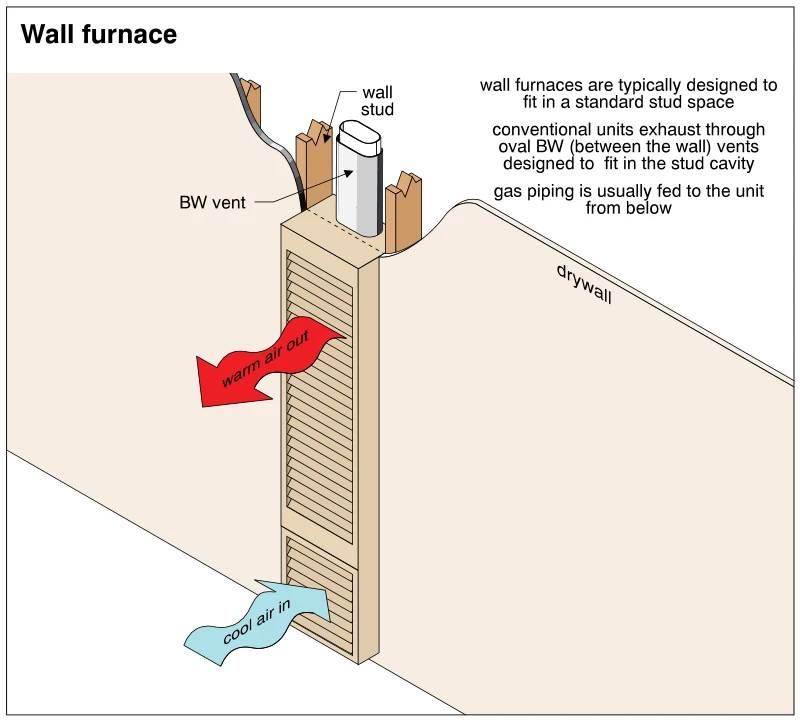 1163
1163Wall furnace
· p. 206
The illustration shows a tall, narrow wall furnace recessed into a drywall partition between wood studs. A cutaway above the furnace exposes an oval BW vent rising through the stud cavity. Arrows show cool room air entering the lower grille and warm air leaving the upper grille. Annotations explain that wall furnaces typically fit a standard stud space and that gas piping is usually supplied from below, although the piping is not shown. No installation defect is depicted.
And Gas Fireplaces ·Gas Fireplaces and Gas Logsp. 207
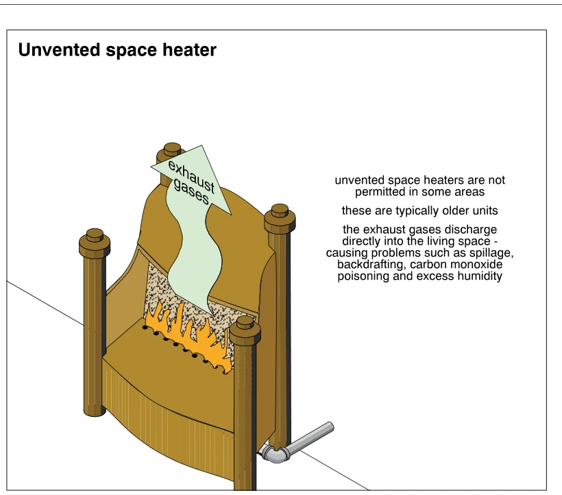 1164
1164Unvented space heater
· p. 207
The illustration shows an older-style gas-fired unvented space heater with an exposed burner flame, a textured panel behind the flame, and a decorative enclosure. A gas supply pipe connects to the lower side of the heater through an elbow. An upward arrow shows exhaust gases discharging directly into the living space rather than through a vent. The annotations warn of spillage, backdrafting, carbon monoxide poisoning, and excess humidity, and note that unvented space heaters are not permitted in some areas.
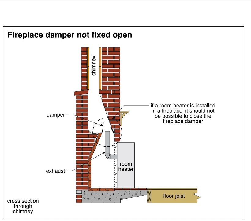 1165
1165Fireplace damper not fixed open
· p. 207
The illustration shows a cross section through a masonry fireplace and chimney with a room heater installed in the fireplace opening. The heater exhaust turns upward into the fireplace beneath the throat damper. A dashed outline emphasizes the damper area, where the damper has not been fixed open. The annotation states that when a room heater is installed in a fireplace, it should not be possible to close the fireplace damper. The section also shows the masonry hearth support and an adjacent floor joist.
 1166
1166Gas fireplace location restrictions
· p. 207
The illustration depicts a bathroom with a gas fireplace installed against the wall beside a bathtub and shower. The fireplace has a mantel, a framed firebox, and burning logs, and is labeled as a standard vent gas fireplace. A red prohibition symbol overlays the fireplace to indicate an unacceptable location. The annotation states that many jurisdictions prohibit gas fireplaces in bathrooms or bed/sitting rooms unless they are direct vent units or specifically approved for those rooms.
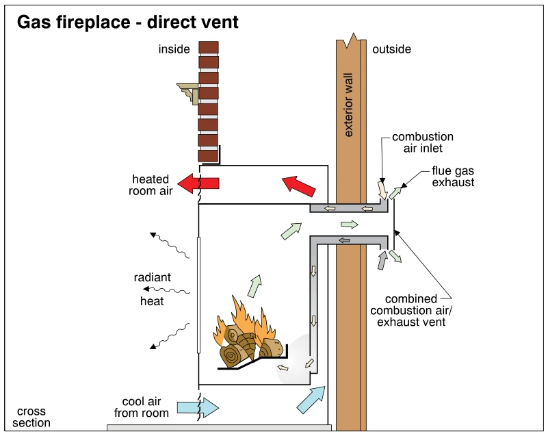 1167
1167Gas fireplace - direct vent
· p. 207
The illustration shows a cross section of a direct-vent gas fireplace installed beside an exterior wall. A combined combustion-air and exhaust vent passes horizontally through the wall, supplying outdoor air to the firebox and discharging flue gases outside through separate passages. Arrows show cool room air entering below the firebox, circulating around it, and returning to the room as heated air at the top. Wavy arrows indicate radiant heat emitted from the fireplace front. The drawing distinguishes room-air circulation from the combustion-air and exhaust paths; no defect is depicted.
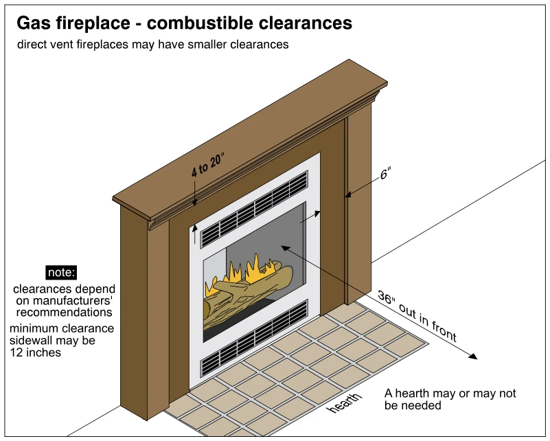 1168
1168Gas fireplace - combustible clearances
· p. 207
The illustration shows a gas fireplace with simulated burning logs, upper and lower grille openings, a projecting mantel, and a wood-colored surround. Clearance arrows identify 4 to 20 inches above the fireplace opening, 6 inches at the side, and 36 inches out in front. A tiled hearth extends in front of the appliance, with a note that a hearth may or may not be needed. Other notes state that clearances depend on manufacturers' recommendations, minimum sidewall clearance may be 12 inches, and direct vent fireplaces may have smaller clearances.