
Related illustrations
 0858
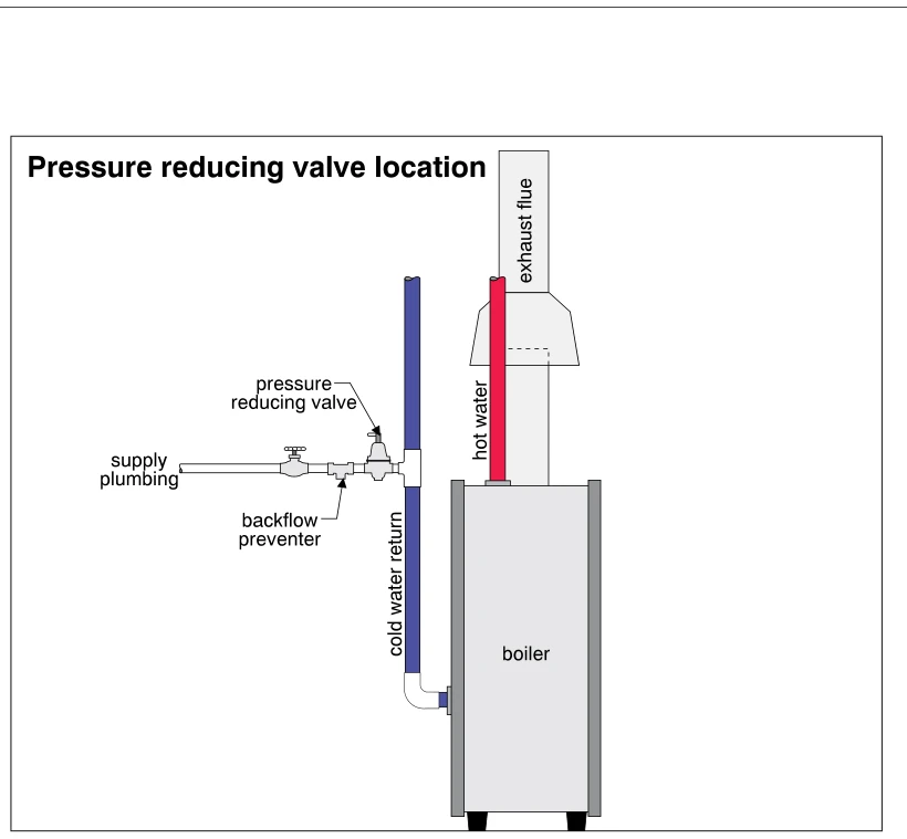
0858Pressure reducing valve location
· p. 145
The illustration shows a heating boiler with a blue cold-water return pipe, a red hot-water supply pipe, and an exhaust flue above it. A horizontal makeup-water supply connects to the cold-water return near the boiler. A
 0852
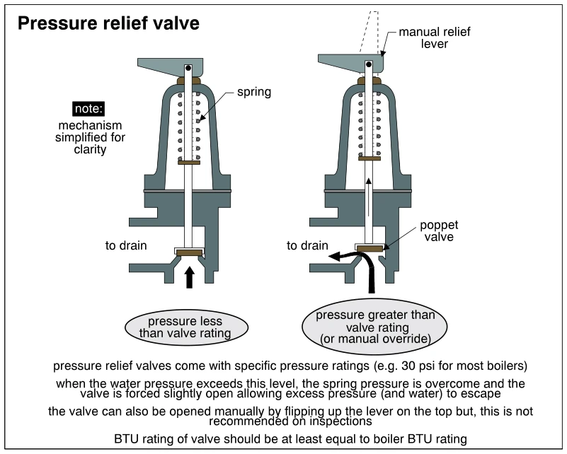
0852Pressure relief valve
· p. 143
Two simplified cross-sections show a boiler pressure relief valve in its closed and open states. On the left, spring force holds the poppet valve seated when water pressure is below the valve rating. On the right, pressu
 1115
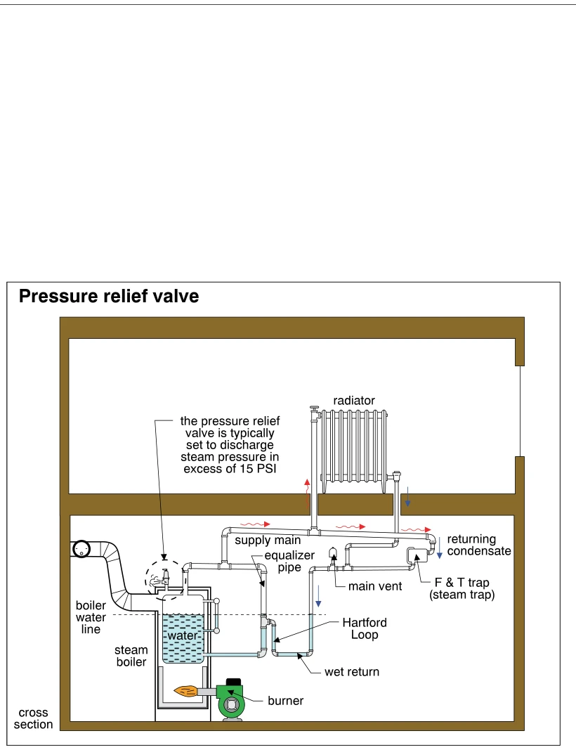
1115Pressure relief valve
· p. 195
The illustration shows a building cross section with a steam boiler below a radiator, connected by a steam supply main and condensate return piping. Red arrows indicate steam movement toward the radiator and along the su
 0862
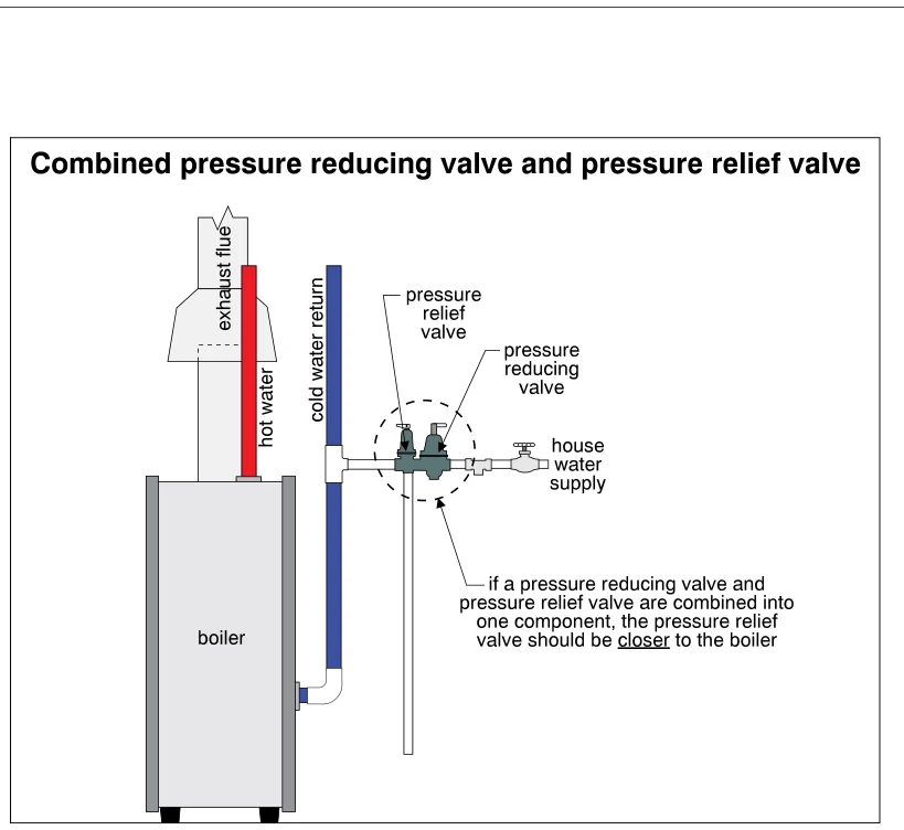
0862Combined pressure reducing valve and pressure relief valve
· p. 146
The illustration shows a hot-water heating boiler with an exhaust flue, a hot-water supply riser, and a cold-water return pipe. The house water supply connects to the boiler return through a combined pressure reducing va
 1581.5
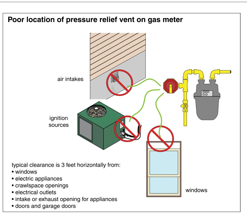
Poor location of pressure relief vent on gas meter
· p. 276
The illustration shows a gas meter, connected gas piping, a shutoff valve, and a pressure regulator with a relief vent. Green lines extend from the vent toward a wall air intake, an electrical connection beside an outdoo
 1599
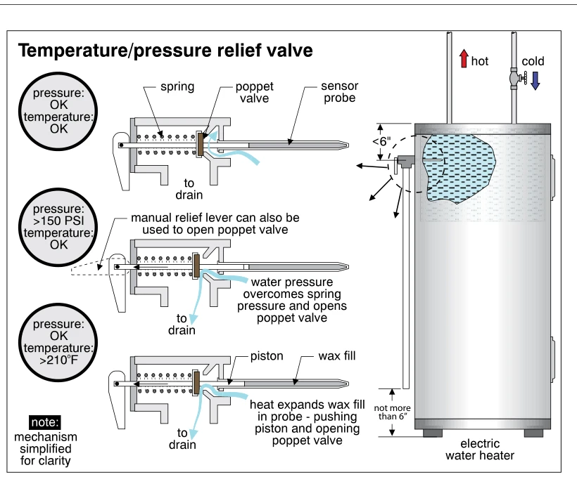
1599Temperature/pressure relief valve
· p. 279
The illustration shows a temperature/pressure relief valve installed near the top of an electric tank-type water heater, with a discharge pipe extending down to within 6 inches of the floor. Three simplified valve cross-
 0875
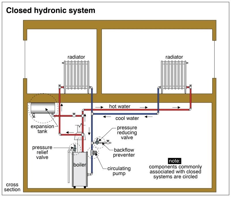
0875Closed hydronic system
· p. 149
A building cross section shows a closed hot-water heating system with a boiler on the lower level and two radiators above. Red supply piping carries hot water to the radiators, while blue return piping carries cooler wat