
Related illustrations
 1355
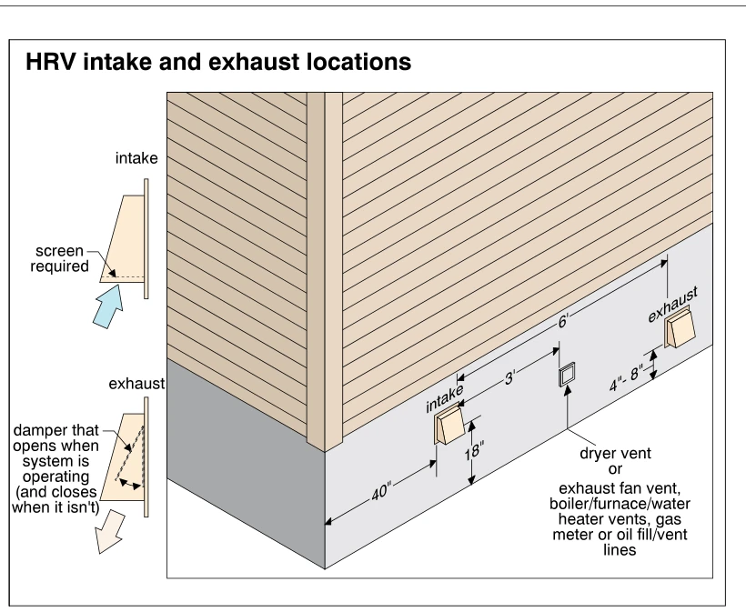
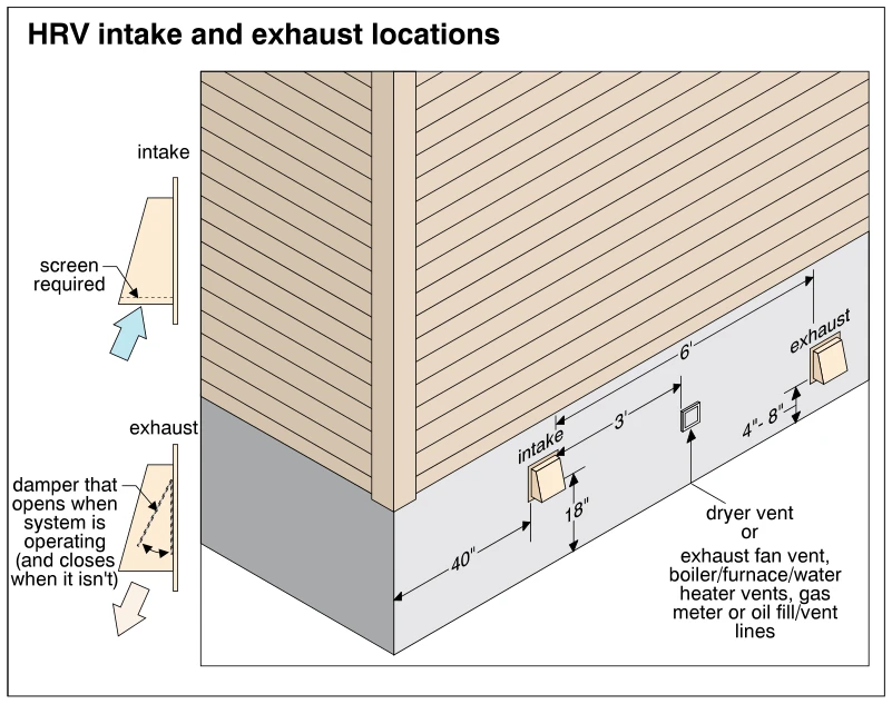
1355HRV intake and exhaust locations
· p. 243
The illustration shows exterior intake and exhaust locations for a heat recovery ventilator on a house wall. Dimension arrows place the intake 40 inches from the building corner and 18 inches above the bottom reference l
 1091
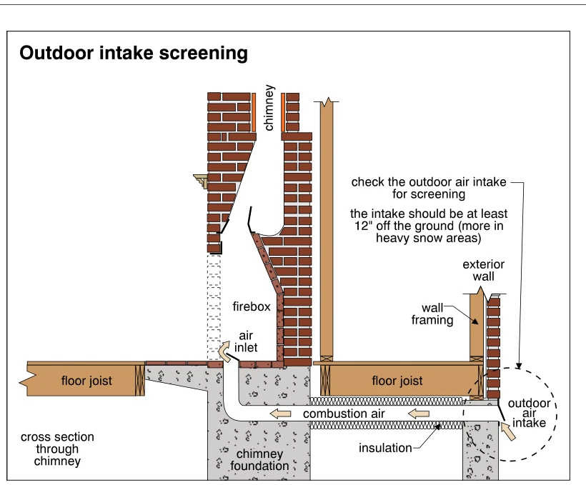
1091Outdoor intake screening
· p. 191
The illustration shows a cross section through a masonry fireplace and chimney with an outdoor combustion-air supply duct. The duct passes through the exterior wall below the floor framing, runs through the chimney found
 1400
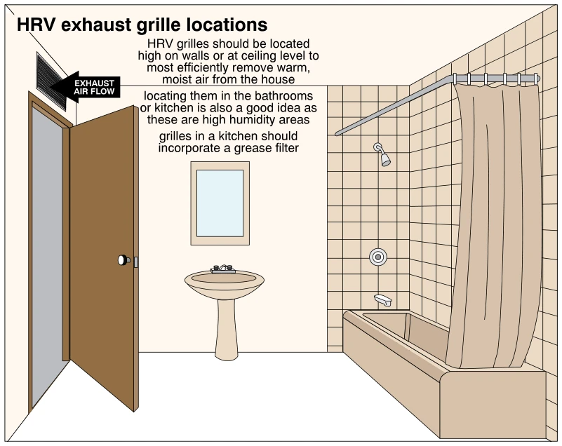
1400HRV exhaust grille locations
· p. 255
The illustration shows a bathroom with an HRV exhaust grille mounted high on the wall above the doorway. An arrow indicates exhaust airflow into the grille. A pedestal sink and a bathtub with shower fixtures and a curtai
 1357.3
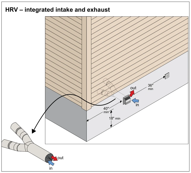
HRV – integrated intake and exhaust
· p. 244
The illustration shows an integrated heat recovery ventilator (HRV) intake and exhaust terminal on an exterior wall near a building corner. Red and blue arrows identify outgoing exhaust air and incoming outdoor air throu