
06Insulation
109 illustrations · printed pages 231-256
The Basicsp. 232
 1300
1300British Thermal Unit (BTU)
· p. 232
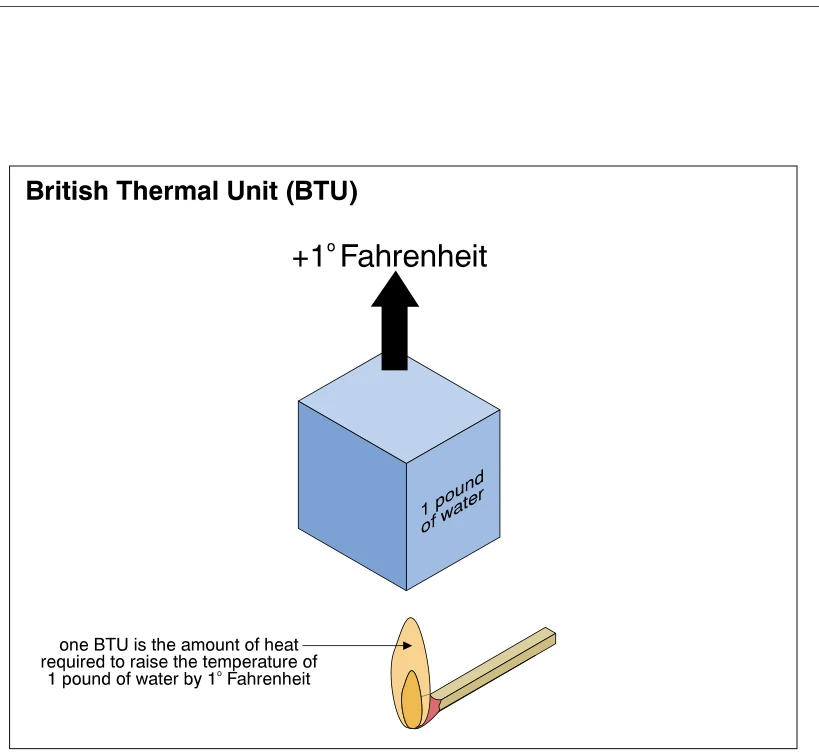
The illustration explains a British Thermal Unit (BTU) using a blue cube representing one pound of water. An upward arrow above the cube indicates a temperature increase of 1° Fahrenheit. A burning match below the cube symbolizes the heat input, with an annotation defining one BTU as the heat required to produce this temperature rise. This is a conceptual explanation of heat energy, not a depiction of a building assembly or installation practice.
 1301
1301Latent heat of vaporization
· p. 232
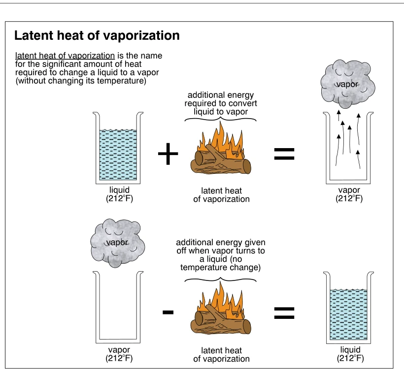
The illustration presents two schematic equations explaining latent heat during liquid–vapor phase changes. In the upper equation, a container of liquid at 212°F plus added heat, symbolized by burning logs, produces vapor at 212°F. Upward arrows show vapor leaving the container. In the lower equation, vapor at 212°F loses energy as it becomes liquid at the same temperature. The annotations emphasize that these phase changes absorb or release energy without changing temperature; no building assembly or installation practice is depicted.
 1302
1302Mechanisms of heat transfer
· p. 232
The illustration explains conduction, radiation, and convection using three side-by-side diagrams. Conduction is shown as heat moving through a solid masonry wall from a warm interior toward a cold exterior. Radiation is represented by waves traveling from the sun toward a house. Convection is illustrated by warm air rising above a pot, with arrows showing cooler air being drawn in from the sides. The figure explains heat-transfer principles rather than depicting an insulation installation or defect.
 1303
1303People and homes release heat
· p. 232
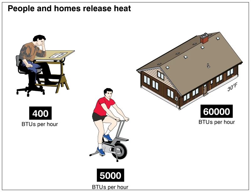
The illustration compares heat release from a seated person, a person riding a stationary exercise bicycle, and a house. The seated person is labeled 400 BTUs per hour, while the exercising person is labeled 5000 BTUs per hour. The house is labeled 60000 BTUs per hour, with a temperature annotation of 30°F beside it. The house is shown with a gable roof, chimney, exterior walls, windows, and a door; no insulation details or defects are depicted.
 1304
1304Thermal conductivity
· p. 232
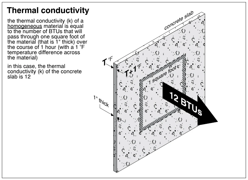
The illustration explains thermal conductivity using a concrete slab shown in perspective. The slab is labeled as 1 inch thick, with a marked area of 1 square foot and temperatures on opposite faces differing by 1 °F. A large arrow labeled "12 BTUs" represents heat passing through the marked area. The accompanying text defines thermal conductivity in terms of heat transfer over one hour and gives the concrete slab a conductivity (k) of 12.
 1305
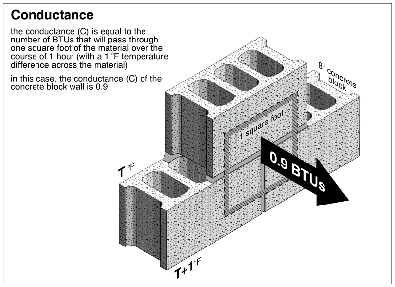
1305Conductance
· p. 232
The illustration shows a cutaway section of an 8-inch hollow concrete block wall with staggered joints. A marked area on the wall face represents one square foot, and the opposite sides are labeled with temperatures differing by 1°F. A large arrow represents 0.9 BTUs of heat passing through the wall. The accompanying text defines thermal conductance as heat transfer through one square foot of material in one hour at a 1°F temperature difference, and gives this wall a conductance of 0.9.
 1306
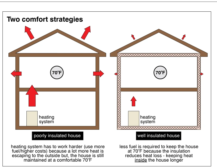
1306Two comfort strategies
· p. 233
Two schematic house sections compare maintaining a 70°F indoor temperature in poorly insulated and well insulated houses. The poorly insulated house has large outward arrows through the roof and walls and a large upward arrow above its heating system, representing greater heat loss and heating demand. The well insulated house shows a continuous insulation layer along the walls, top-floor ceiling, and bottom floor, with smaller heat-loss and heating arrows. The annotations explain that both houses maintain the same comfortable temperature, but the well insulated house requires less fuel.
 1307
1307Convective loop
· p. 233
Two bottle-shaped enclosures compare air circulation in an open air space with air held within insulation. In the left enclosure, arrows show warm air rising through the center and cooler air descending along the sides, forming a convective loop. The right enclosure is filled with insulation, with warm air indicated near the bottom and cool conditions outside both sides. The annotation explains that insulation holds air in small pockets, preventing air movement and the formation of convective loops.
 1308
1308R-value per inch
· p. 233
The illustration shows four separate material samples with their R-values per inch of thickness. Fiberglass insulation is labeled 3.0, concrete 0.08, stucco 0.2, and pine board 1.25. The samples use distinct surface textures, including wood grain on the pine board. The figure compares thermal resistance rather than showing an installed assembly or an installation defect.
 1309
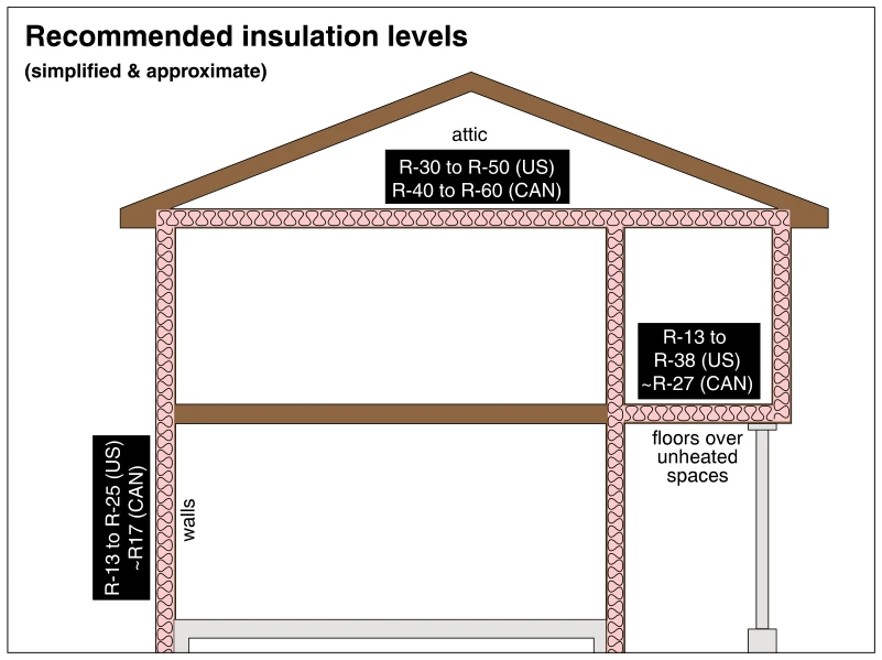
1309Recommended insulation levels
· p. 233
A schematic house section shows recommended insulation levels at the attic floor, exterior walls, and a floor over an unheated space. Pink insulation symbols trace these parts of the thermal enclosure, while the sloped roof above the attic is not shown insulated. The attic recommendation is R-30 to R-50 for the US and R-40 to R-60 for Canada. Wall recommendations are R-13 to R-25 for the US and approximately R17 for Canada; floors over unheated spaces are labeled R-13 to R-38 for the US and approximately R-27 for Canada. The illustration explicitly identifies these recommendations as simplified and approximate.
 1310
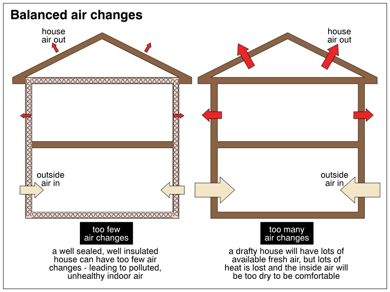
1310Balanced air changes
· p. 233
Two schematic house sections compare insufficient and excessive air exchange through the building envelope. The left house has insulation shown around its walls, ceiling, and lowest floor, with small arrows indicating outside air entering low in the house and indoor air escaping above. Its annotations warn that a well-sealed, well-insulated house can have too few air changes, resulting in polluted, unhealthy indoor air. The right house has no insulation depicted and larger arrows showing greater incoming and outgoing airflow. Its annotations identify excessive air changes in a drafty house as a source of heat loss and overly dry indoor air.
 1311
1311Absolute and relative humidity
· p. 233
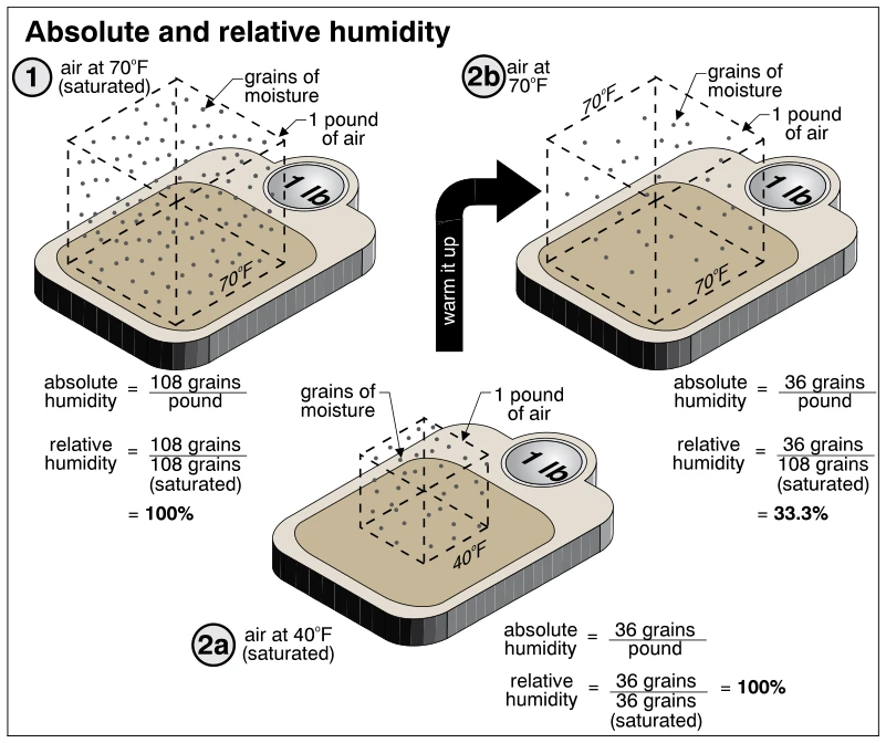
Three schematic air samples sit on scales marked 1 lb, with dots representing grains of moisture and dashed outlines representing the air volumes. The saturated 70°F sample contains 108 grains of moisture per pound and has 100% relative humidity. The saturated 40°F sample contains 36 grains per pound and also has 100% relative humidity. An arrow labeled “warm it up” connects the 40°F sample to a 70°F sample: moisture content remains 36 grains per pound, but relative humidity drops to 33.3%. The illustration compares moisture content and relative humidity at different temperatures rather than showing a building assembly or defect.
 1312
1312How moisture moves
· p. 234
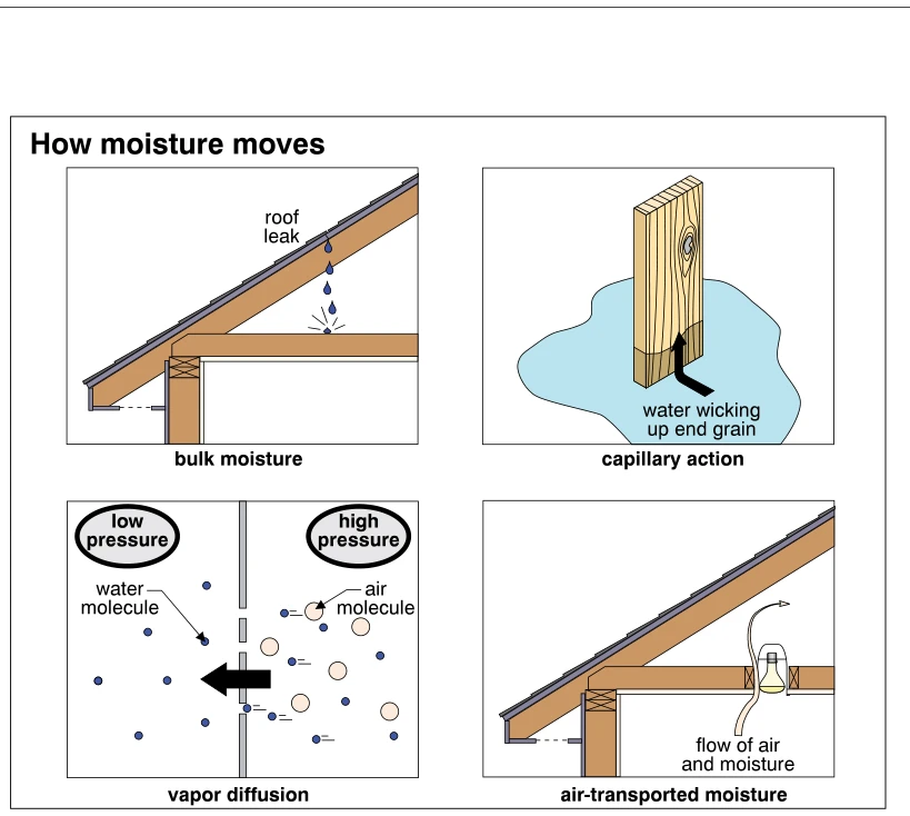
The illustration uses four panels to show mechanisms of moisture movement in buildings. The bulk-moisture panel shows a roof leak dripping onto horizontal framing below a sloped roof. The capillary-action panel shows water wicking upward through the end grain of a wood member standing in water. The vapor-diffusion panel depicts water molecules moving from the high-pressure side toward the low-pressure side of a dividing layer. The air-transported-moisture panel shows air and moisture flowing through a ceiling opening around a recessed light into the roof space.
 1313
1313Stack effect
· p. 234
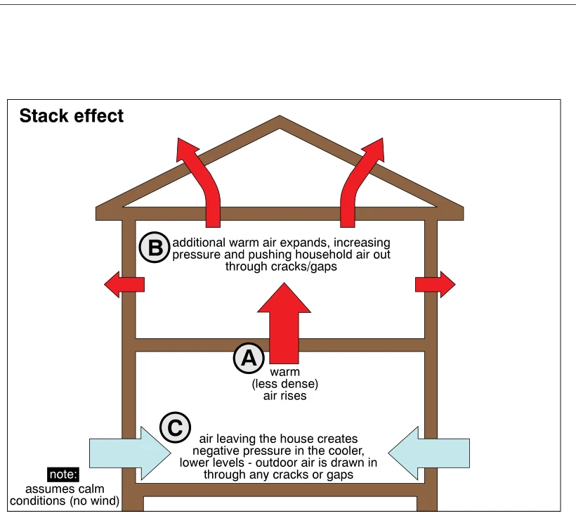
A schematic house section illustrates stack-effect airflow under calm, no-wind conditions. A large upward arrow shows warm, less dense air rising from the lower level to the upper level. Red outward arrows at the upper walls and roof depict household air escaping through cracks and gaps as upper-level pressure increases. Light blue inward arrows at the lower walls show outdoor air being drawn in by negative pressure at the cooler, lower levels.
 1314
1314Neutral pressure plane
· p. 234
A schematic house section illustrates indoor air pressures relative to outside pressure under calm, no-wind conditions. A dashed horizontal line marks the neutral pressure plane, where the indoor and outdoor pressures are equal. Above this plane, higher indoor pressure drives air outward through the upper walls and roof, shown by red exfiltration arrows. Below the plane, lower indoor pressure draws outside air inward through the lower walls, shown by gray infiltration arrows. Pressure gauges indicate the relative pressures outside, above, at, and below the neutral plane.
 1315
1315Dew point
· p. 234
Two schematic examples use vapor clouds, cooling arrows, and water droplets to illustrate dew point. Example 1 shows air at 80°F and 50% relative humidity cooling by 20°F to reach 100% relative humidity and a dew point of 60°F. Example 2 shows air at 80°F and 90% relative humidity cooling by only 2°F to reach 100% relative humidity and a dew point of 78°F. Droplets beneath the saturated clouds represent condensation, illustrating that air with higher initial relative humidity requires less cooling to reach its dew point. No building assembly or installation practice is depicted.
 1316
1316Vapor diffusion
· p. 234
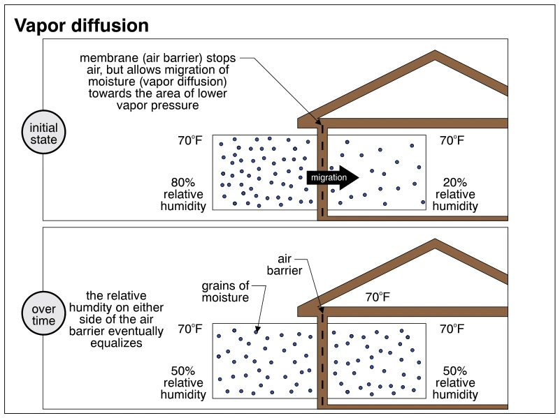
Two schematic house sections illustrate water vapor diffusion through an air-barrier membrane. In the initial state, both sides are at 70°F, but relative humidity is 80% on the left and 20% on the right; an arrow shows moisture migrating toward the lower-vapor-pressure side. Dots represent moisture, with more dots initially on the high-humidity side. The lower panel shows relative humidity eventually equalizing at 50% on both sides while temperatures remain at 70°F. The illustration distinguishes stopping air movement from stopping water vapor diffusion.
 1317
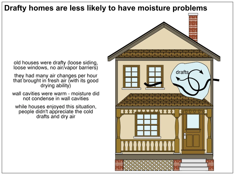
1317Drafty homes are less likely to have moisture problems
· p. 234
The illustration shows the front elevation of an older two-story house with a gabled roof, chimney, windows, and covered porch. Curving arrows at the upper story represent drafts and air movement through the house. Annotations explain that loose siding, loose windows, and absent air/vapor barriers allowed frequent air changes that brought in fresh air with drying potential. They also state that warm wall cavities avoided moisture condensation. The figure contrasts these moisture benefits with occupants' discomfort from cold drafts and dry air.
 1318
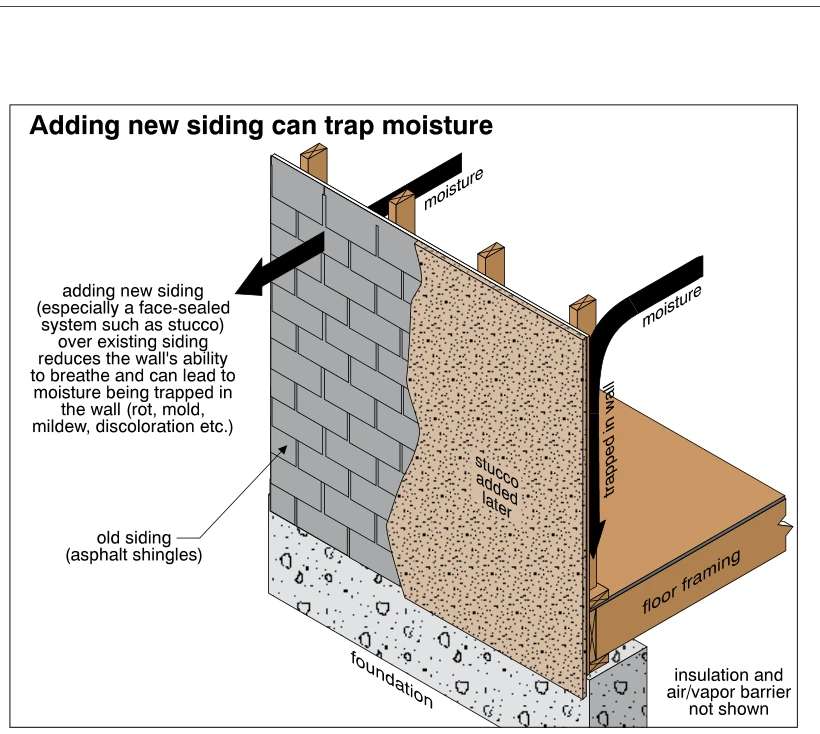
1318Adding new siding can trap moisture
· p. 235
The illustration shows a cutaway exterior wall with existing asphalt-shingle siding partially covered by stucco added later. Wood wall framing and floor framing are shown above a foundation. Black arrows contrast moisture passing outward through the original siding with moisture becoming trapped behind the added stucco. The annotation warns that adding a face-sealed siding system over existing siding reduces the wall's ability to dry and can lead to rot, mold, mildew, and discoloration. Insulation and the air/vapor barrier are explicitly noted as not shown.
 1319
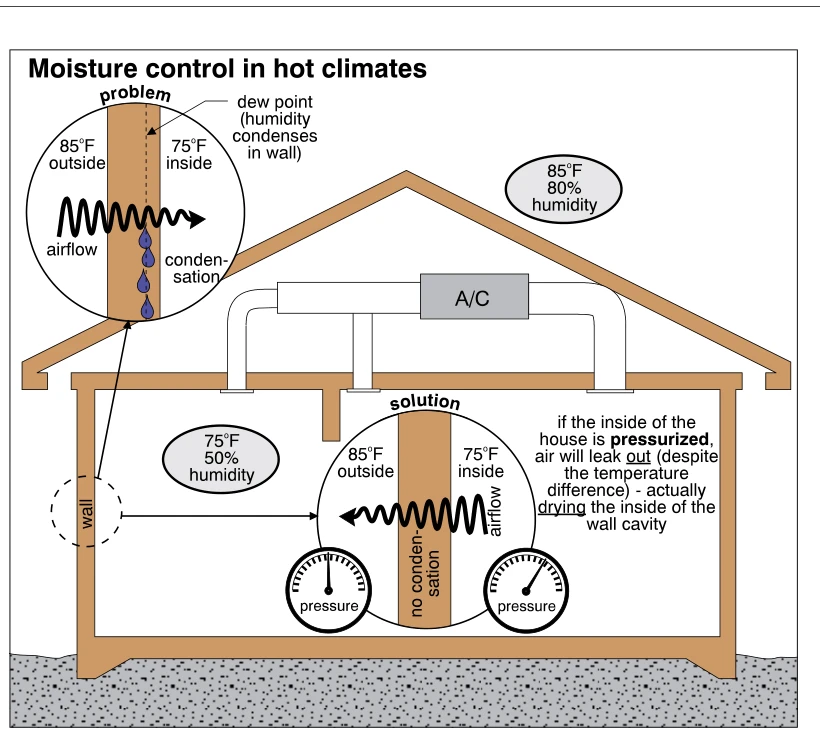
1319Moisture control in hot climates
· p. 235
A schematic house section shows an air-conditioning unit and ductwork, with outdoor conditions of 85°F and 80% humidity and indoor conditions of 75°F and 50% humidity. An enlarged problem detail shows warm outdoor air flowing inward through the wall, reaching the dew point within the assembly and producing condensation. An enlarged solution detail shows higher indoor pressure driving air outward through the wall, with no condensation depicted. Pressure gauges illustrate the pressure difference, and an annotation explains that outward leakage of indoor air dries the wall cavity despite the temperature difference.
 1320
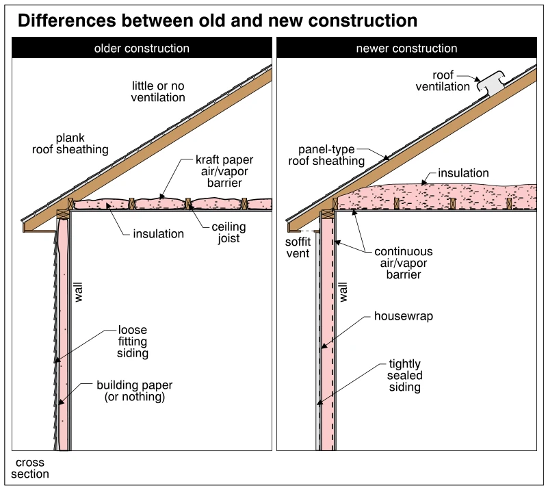
1320Differences between old and new construction
· p. 235
Two cross sections compare older and newer construction at the exterior wall, attic floor, and sloping roof. The older assembly shows plank roof sheathing, little or no attic ventilation, insulation between ceiling joists, and a kraft paper air/vapor barrier. Its exterior wall has loose fitting siding over building paper or no paper. The newer assembly shows panel-type roof sheathing, a soffit vent and roof vent, and thicker attic insulation extending above the ceiling joists. It also depicts a continuous air/vapor barrier at the wall and ceiling, with housewrap behind tightly sealed siding.
 1321
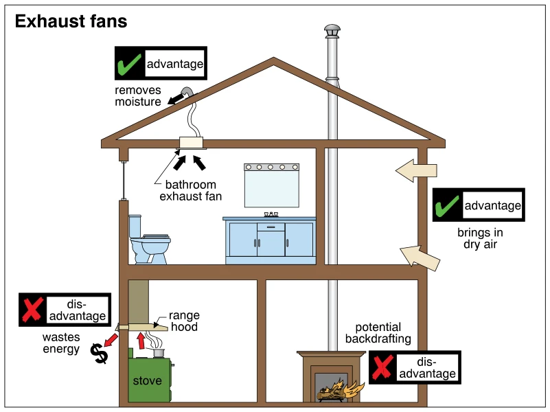
1321Exhaust fans
· p. 235
A cutaway of a two-story house illustrates the advantages and disadvantages of exhaust ventilation. A ceiling-mounted bathroom exhaust fan discharges moisture through a duct and roof outlet, while a range hood above a stove exhausts through an exterior wall. Arrows entering the opposite wall indicate replacement air, labeled as bringing in dry air. The drawing identifies energy loss from exhaust ventilation and potential backdrafting at a fireplace connected to a vertical chimney.
 1322
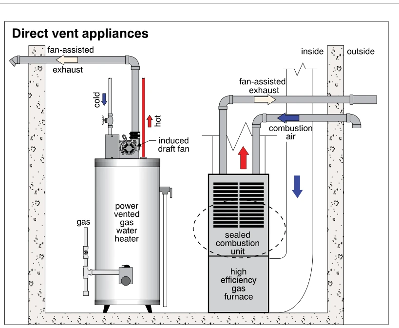
1322Direct vent appliances
· p. 236
The illustration shows a power-vented gas water heater and a high-efficiency gas furnace with exhaust pipes routed through exterior walls. The water heater has an induced draft fan at its top, hot and cold water connections, and a gas supply connection. Its fan-assisted exhaust runs upward and then horizontally through the wall. The furnace has a sealed combustion unit with separate outdoor combustion-air intake and fan-assisted exhaust pipes. Arrows indicate incoming combustion air and outgoing exhaust, distinguishing these flow paths at the furnace.
 1323
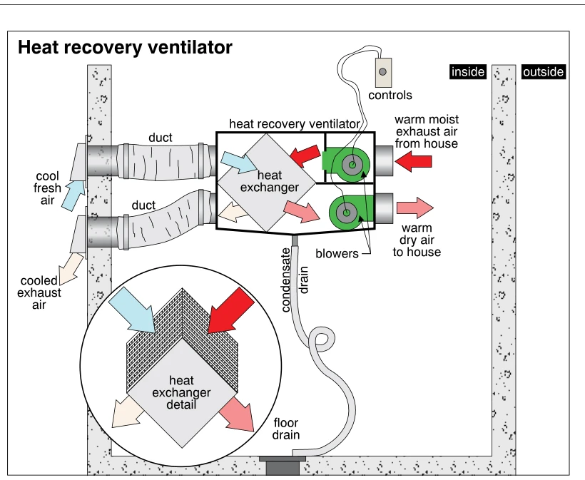
1323Heat recovery ventilator
· p. 236
The illustration shows a heat recovery ventilator with two blowers, a heat exchanger, controls, and ducts passing through an exterior wall. Colored arrows trace cool fresh outdoor air through the exchanger to become warm dry supply air to the house, while warm moist house air passes through the exchanger and leaves as cooled exhaust air. An enlarged detail depicts the exchanger's layered passages and the two separate air streams. A condensate drain runs from the bottom of the unit through a loop to a floor drain. The drawing explains the assembly and airflow without identifying any defects.
 1324
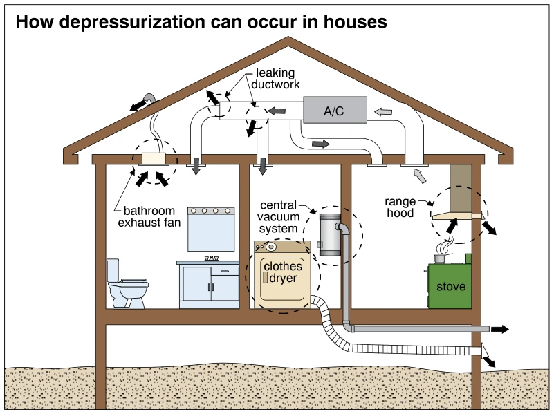
1324How depressurization can occur in houses
· p. 236
A house cross-section illustrates several ways air can be removed from the interior, causing depressurization. An attic air-conditioning system has leaking ductwork, with arrows showing air escaping into the attic. A bathroom exhaust fan vents through the roof, while a central vacuum system and clothes dryer discharge through the exterior wall. A range hood above the stove also exhausts air outdoors. Arrows and dashed circles highlight the air-removal equipment and duct leakage locations.
 1325
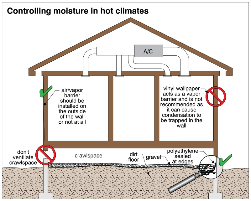
1325Controlling moisture in hot climates
· p. 236
The illustration shows a house section with an attic-mounted air-conditioning unit and ductwork, exterior walls, and a crawlspace over a dirt floor. For hot climates, it recommends placing an air/vapor barrier on the outside of the wall or omitting it. Interior vinyl wallpaper is discouraged because it acts as a vapor barrier and can trap condensation in the wall. A crossed-out crawlspace opening indicates that the crawlspace should not be ventilated. A magnified edge detail and check mark emphasize a polyethylene ground covering sealed at its edges, with gravel also identified.
 1326
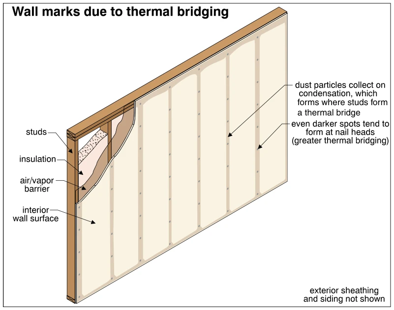
1326Wall marks due to thermal bridging
· p. 236
The illustration shows a wood-framed insulated wall with a cutaway exposing studs, insulation, and an air/vapor barrier behind the interior wall surface. Vertical discolored bands on the interior finish follow the stud locations. The annotation explains that dust particles collect on condensation where the studs create thermal bridges. Darker spots at nail heads indicate greater localized thermal bridging. Exterior sheathing and siding are explicitly not shown.
 1327
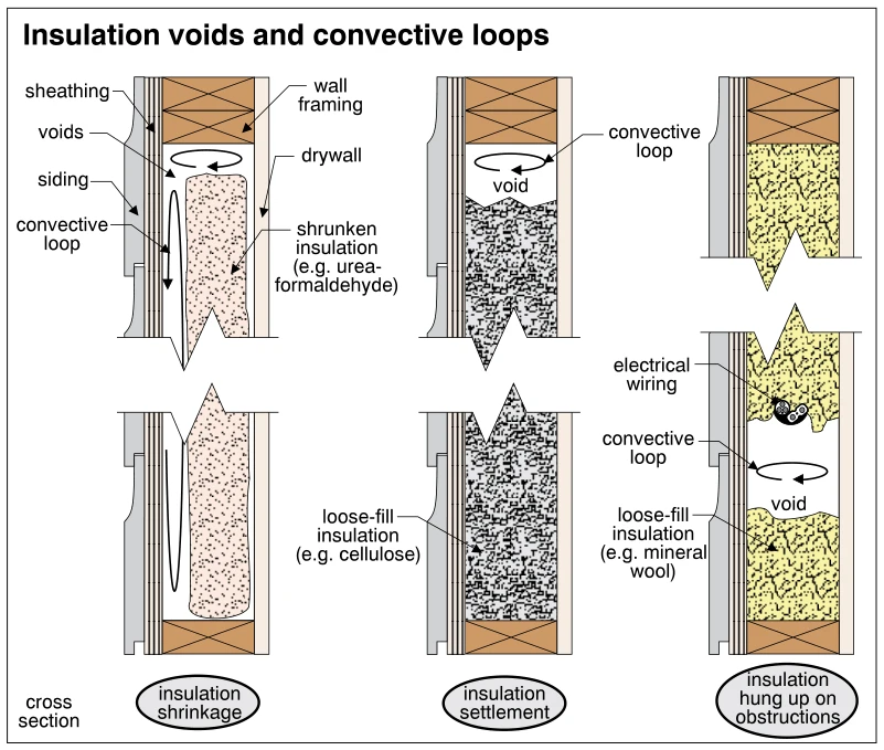
1327Insulation voids and convective loops
· p. 236
Three wall cross sections illustrate insulation voids and the convective air circulation that can occur within them. The left section shows shrunken insulation separated from the surrounding wall assembly, with arrows indicating air movement above and alongside the insulation. The middle section shows loose-fill insulation settlement leaving a void at the top of the cavity. The right section shows loose-fill insulation hung up on electrical wiring, leaving a void below the obstruction. Each assembly includes exterior siding and sheathing, wood wall framing, and interior drywall.
 1328
1328Wind washing
· p. 237
The cross section shows an insulated exterior wall meeting a sloped roof and an insulated attic floor at the eave. Heavy arrows depict wind entering through the soffit area and exterior wall, then moving through the attic and wall insulation. An annotation explains that this wind washing reduces insulation R-values, with fiberglass and mineral wool particularly susceptible. A circular detail shows housewrap outside the wall insulation deflecting wind and identifies its role in reducing wind washing. Wall sheathing is omitted for clarity.
 1329
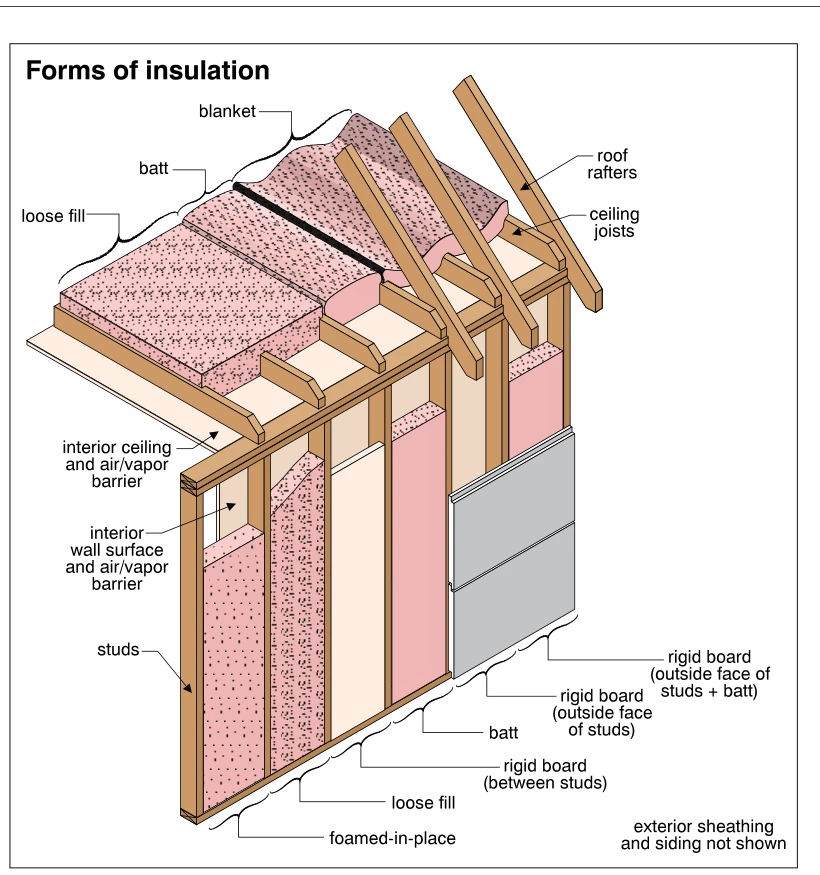
1329Forms of insulation
· p. 237
A cutaway of wood-framed wall and ceiling assemblies illustrates different forms of insulation. Loose fill, batt, and blanket insulation are shown between ceiling joists beneath exposed roof rafters. Wall cavities illustrate foamed-in-place, loose-fill, rigid-board, and batt insulation. Rigid board is also shown across the outside faces of studs, both alone and combined with cavity batts. Interior wall and ceiling surfaces with air/vapor barriers are identified; exterior sheathing and siding are explicitly omitted.
 1330
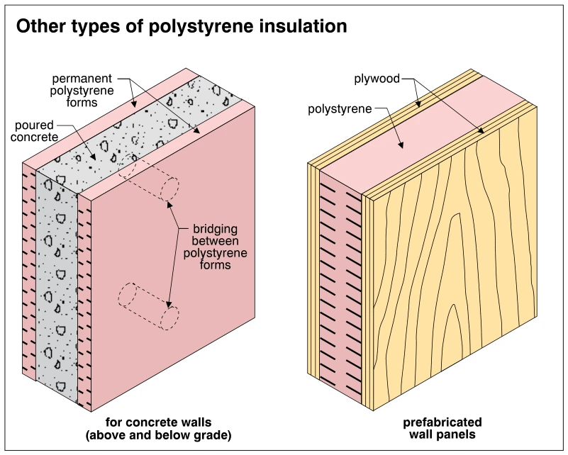
1330Other types of polystyrene insulation
· p. 237
The illustration shows two wall assemblies incorporating polystyrene insulation. On the left, poured concrete is sandwiched between permanent polystyrene forms, with bridging connecting the forms through the concrete core. This assembly is identified as suitable for concrete walls above and below grade. On the right, a prefabricated wall panel has a polystyrene core between plywood faces. No defects or installation errors are depicted.
 1331
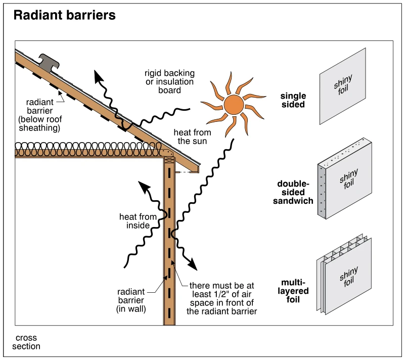
1331Radiant barriers
· p. 237
A roof-and-wall cross section shows radiant barriers below the roof sheathing and within the exterior wall assembly. Wavy arrows illustrate radiant heat from the sun and from inside being reflected at the barriers. The wall detail specifies at least 1/2 inch of air space in front of the radiant barrier. Ceiling insulation is shown at the eave, and a label identifies rigid backing or insulation board. Three separate product sketches depict single-sided shiny foil, a double-sided sandwich, and multilayered foil.
Air/Vapor Barriers (Vapor Retarders)p. 238
 1332
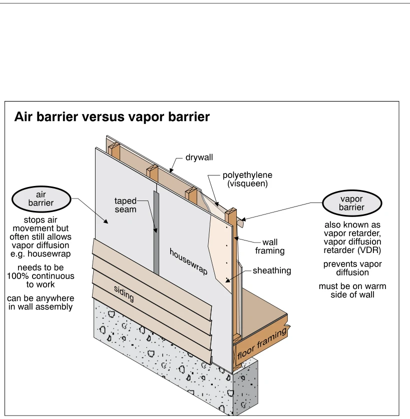
1332Air barrier versus vapor barrier
· p. 238
A cutaway wood-framed exterior wall illustrates the different functions of an air barrier and a vapor barrier. Exterior siding is partially removed to expose housewrap with a taped seam over sheathing, while the interior layers include polyethylene and drywall. The air-barrier annotations emphasize stopping air movement, maintaining complete continuity, and potentially allowing vapor diffusion. The vapor-barrier annotations identify polyethylene as a vapor retarder that prevents vapor diffusion and state that it must be on the warm side of the wall. The wall is shown supported above a concrete foundation with adjacent floor framing.
 1333
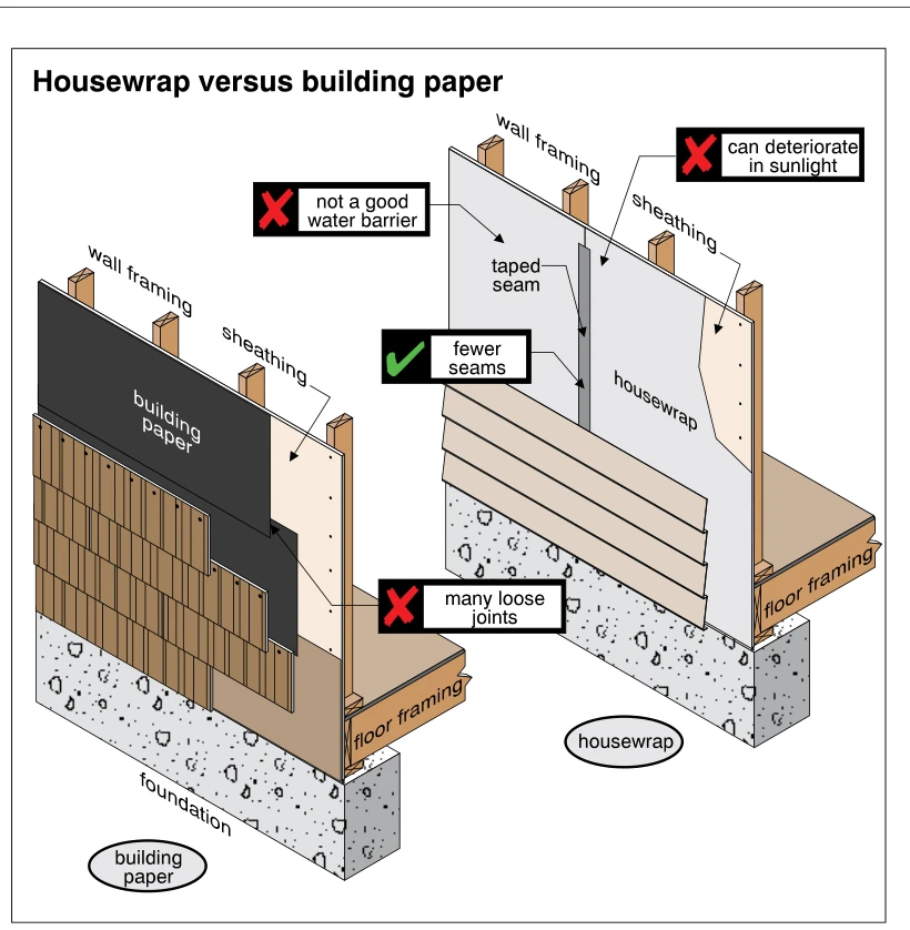
1333Housewrap versus building paper
· p. 238
Two cutaway exterior wall assemblies compare building paper on the left with housewrap on the right, installed over sheathing and behind exterior cladding. Both show wood wall and floor framing supported by concrete foundations. The building-paper assembly has overlapping sheets behind shingle cladding, with a warning identifying many loose joints. The housewrap assembly has horizontal lap siding and a taped vertical seam, with fewer seams marked as an advantage. Additional warnings pointing to the housewrap state that it is not a good water barrier and can deteriorate in sunlight.
 1334
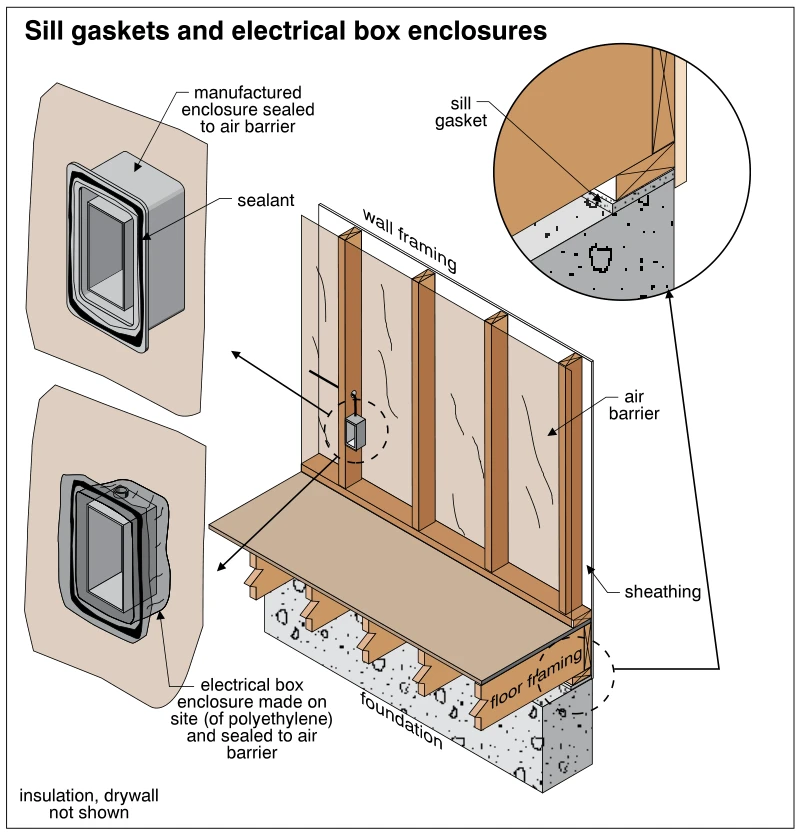
1334Sill gaskets and electrical box enclosures
· p. 238
The illustration shows a wood-framed wall and floor assembly supported on a concrete foundation, with an air barrier at the wall framing. Two enlarged electrical-box details show a manufactured enclosure and a site-made polyethylene enclosure, each sealed to the air barrier. Sealant is identified at the perimeter of the manufactured enclosure. A circular detail shows a sill gasket between the wood sill and the concrete foundation. These details illustrate air-leakage control at electrical penetrations and the sill-to-foundation junction; insulation and drywall are explicitly omitted.
 1335
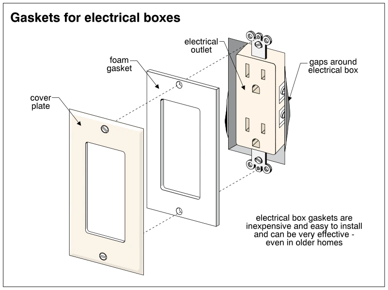
1335Gaskets for electrical boxes
· p. 238
An exploded view shows a duplex electrical outlet, a foam gasket, and a cover plate. The gasket fits behind the cover plate, with its central opening and screw holes aligned with the outlet and plate. A callout identifies gaps around the electrical box at the wall opening. The illustration presents the gasket as an inexpensive, easily installed air-sealing measure that can be effective even in older homes.
Venting Roofsp. 239
 1336
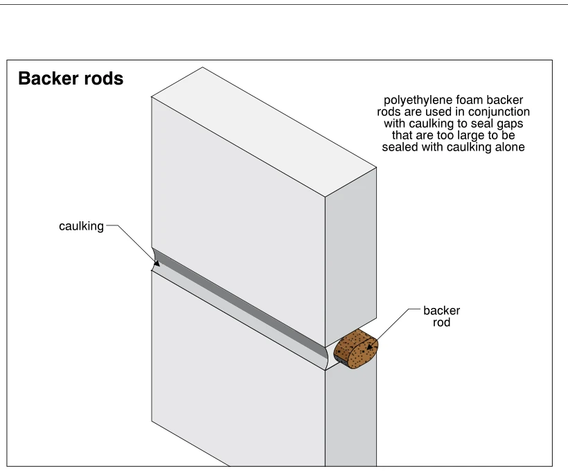
1336Backer rods
· p. 239
The illustration shows a horizontal joint between two building elements, with caulking applied along the exposed face. A cylindrical polyethylene foam backer rod is fitted into the gap behind the caulking, with its end exposed to show its position within the joint. The annotation explains that backer rods are used with caulking to seal gaps too large for caulking alone.
 1337
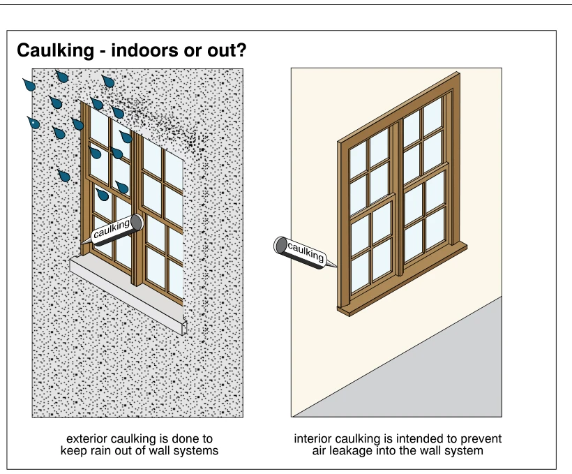
1337Caulking - indoors or out?
· p. 239
Two side-by-side views compare exterior and interior caulking around a window assembly. The exterior view shows rain droplets and a caulking applicator directed at the window-to-wall joint above the sill. The interior view shows an applicator directed at the joint between the window trim and the interior wall. The captions distinguish exterior caulking for keeping rain out of wall systems from interior caulking for preventing air leakage into the wall system.
 1338
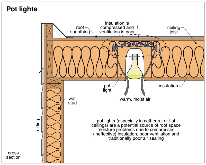
1338Pot lights
· p. 239
The cross section shows a recessed pot light penetrating an insulated ceiling beneath roof sheathing, adjacent to an insulated exterior wall. Insulation is compressed above the light housing, restricting the space available for roof ventilation. Arrows show warm, moist indoor air leaking upward around the fixture, with moisture droplets depicted above the housing. The annotation identifies compressed insulation, poor ventilation, and poor air sealing around pot lights as potential causes of roof-space moisture problems, especially in cathedral or flat ceilings.
 1339
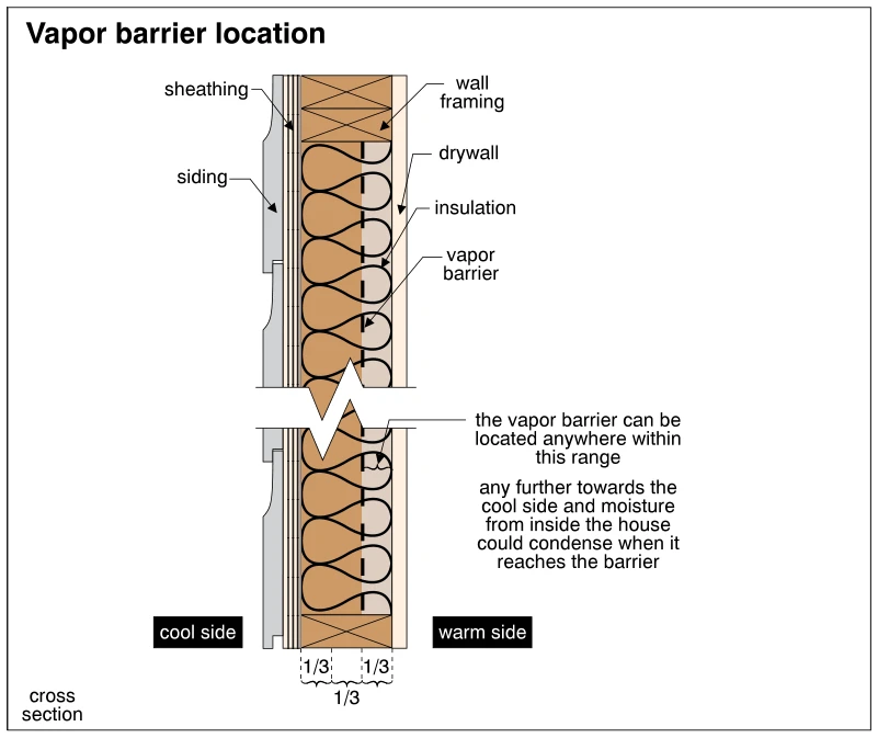
1339Vapor barrier location
· p. 239
The illustration shows a cross section of an insulated framed wall, with siding and sheathing on the cool side and drywall on the warm side. Wall framing encloses the insulation, and a dashed vertical line represents the vapor barrier within the insulation. The insulation depth is divided into thirds, with an annotation indicating that the vapor barrier may be located within the warm-side third. A warning explains that moving the barrier farther toward the cool side could allow moisture from inside the house to condense on it.
 1340
1340Cover crawlspace floor
· p. 239
A schematic house section compares an uncovered crawlspace earth floor on the left with a vapor-barrier-covered floor on the right. Wavy lines rise from the exposed soil, and pouring buckets illustrate the significant amount of moisture that can enter the house environment. The recommended side shows a ground vapor barrier ballasted with gravel and sealed at the foundation edge; the annotation also specifies sealing joints and gives 6 mil polyethylene as an example. A red X marks the uncovered approach and a green check marks the covered approach. A prohibition symbol at a foundation opening accompanies the instruction not to ventilate the crawlspace.
 1341
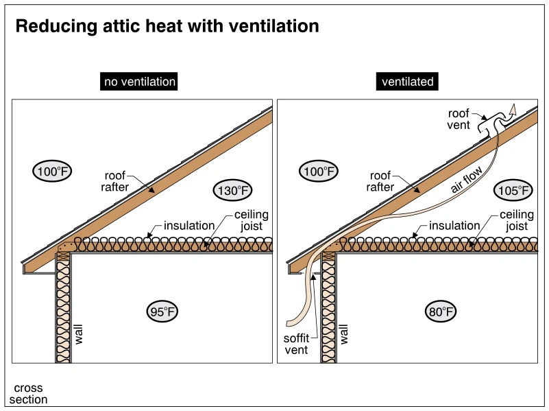
1341Reducing attic heat with ventilation
· p. 239
Two cross sections compare attic and room temperatures beneath an unventilated roof and a ventilated roof, both with an indicated outdoor temperature of 100°F. Each assembly shows a sloped roof rafter, ceiling joist, attic-floor insulation, and an insulated exterior wall. The unventilated example indicates an attic temperature of 130°F and a room temperature of 95°F. In the ventilated example, arrows show air entering through a soffit vent, passing above the insulation, and exiting through a roof vent; the indicated attic and room temperatures are 105°F and 80°F, respectively.
 1342
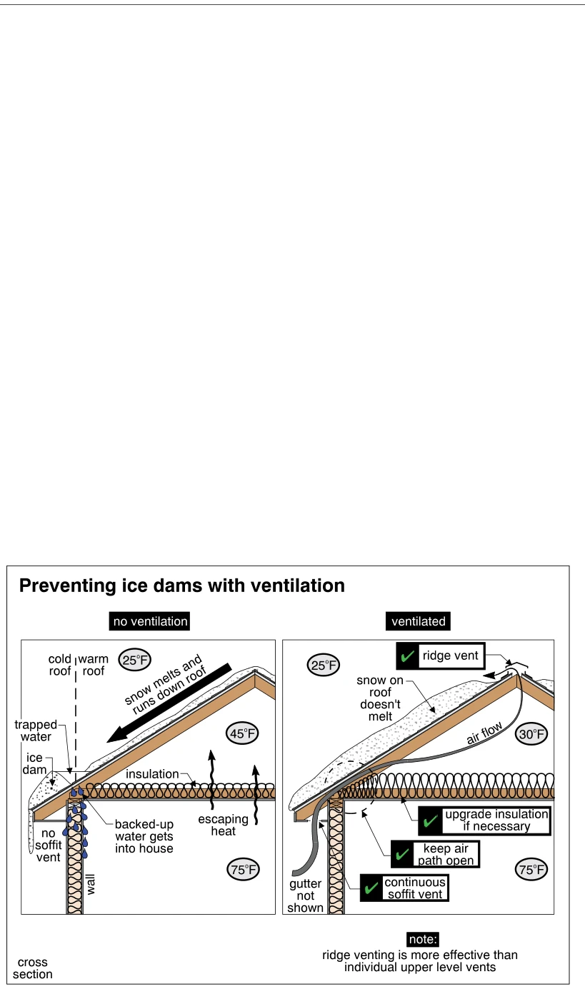
1342Preventing ice dams with ventilation
· p. 240
Two roof-and-wall cross sections compare an unventilated attic with a soffit-to-ridge ventilated attic under snow-covered roofs. In the unventilated example, escaping indoor heat warms the attic to 45°F, causing snow to melt and run toward the cold eave, where an ice dam traps water that backs up into the house. The ventilated example shows outside air entering a continuous soffit vent, passing through an open air path above the eave insulation, and exiting a ridge vent. Its attic is labeled 30°F with 25°F outdoors and 75°F indoors, and the roof snow remains unmelted. Checkmarked annotations recommend a ridge vent, continuous soffit ventilation, an unobstructed air path, and insulation upgrades if necessary.
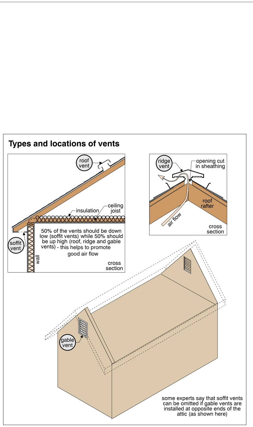 1343
1343Types and locations of vents
· p. 240
The illustration shows roof, soffit, ridge, and gable vent locations using two cross sections and a cutaway perspective of a gable-roofed building. The eave section shows insulation at the ceiling and wall, a low soffit vent, and a roof vent higher on the slope; its annotation recommends equal proportions of low and high vents. The ridge detail shows air flowing through an opening cut in the roof sheathing beneath a ridge vent. The perspective shows louvered gable vents at opposite ends of the attic, with an annotation stating that some experts consider soffit vents optional in this arrangement.
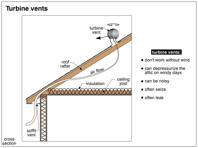 1344
1344Turbine vents
· p. 240
A cross section shows a sloped roof with a turbine vent mounted above the roof surface and a soffit vent at the eave. An airflow path runs from the soffit vent into the attic and up to the turbine vent, with arrows indicating exhaust and turbine rotation. Roof rafters, ceiling joists, and insulation at the ceiling and exterior wall are shown. Notes identify turbine-vent limitations: dependence on wind, possible attic depressurization on windy days, noise, seizure, and leakage. No specific damaged vent or active leak is drawn.
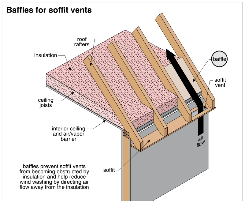 1345
1345Baffles for soffit vents
· p. 240
The cutaway illustration shows a roof eave with sloping rafters above insulated ceiling joists and an interior ceiling and air/vapor barrier. A baffle installed between rafters maintains a ventilation passage above the insulation at the soffit. A large arrow shows outside air entering through the soffit vent and moving upward along the baffle toward the roof space. The annotation explains that baffles prevent insulation from obstructing soffit vents and reduce wind washing by directing airflow away from the insulation.
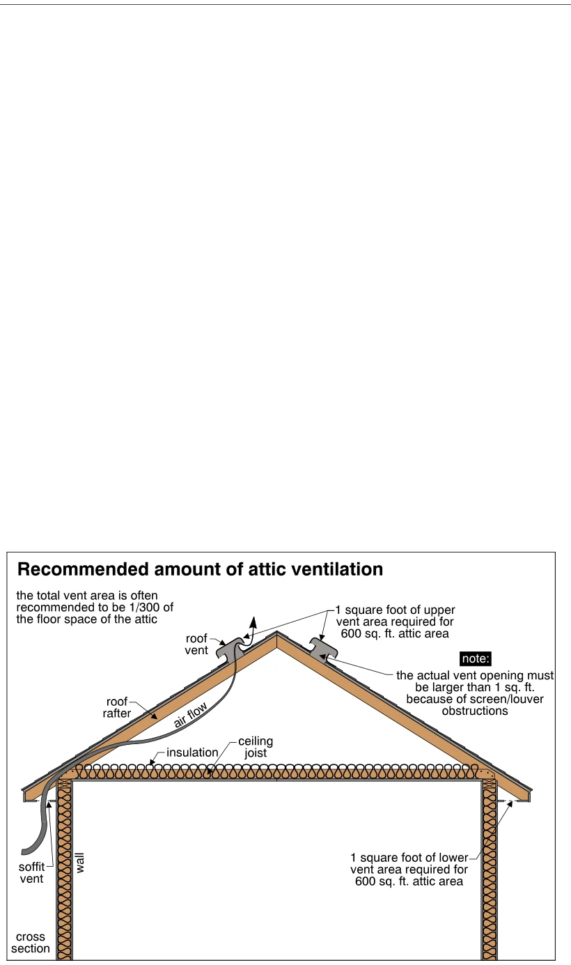 1346
1346Recommended amount of attic ventilation
· p. 241
A cross section of a gable roof shows an insulated attic floor, roof rafters, exterior walls, soffit vents, and roof vents near the ridge. Arrows show air entering at the soffit and moving upward through the attic to a roof vent. The illustration recommends total vent area equal to 1/300 of the attic floor area, divided into one square foot of upper ventilation and one square foot of lower ventilation per 600 square feet of attic area. A note explains that actual vent openings must be larger to account for screen or louver obstructions.
 1347
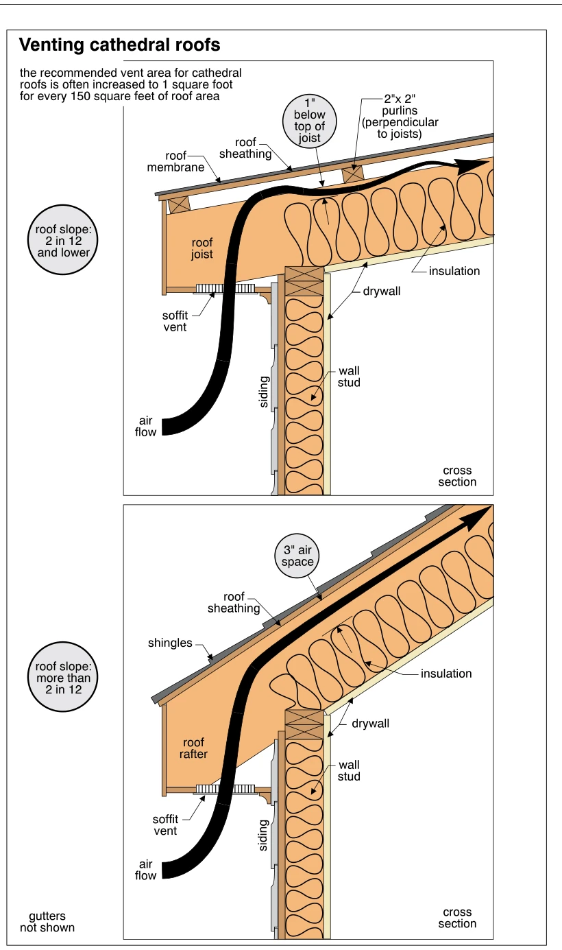
1347Venting cathedral roofs
· p. 241
Two cross sections illustrate cathedral-roof ventilation details for slopes of 2 in 12 and lower and slopes greater than 2 in 12. The low-slope assembly has a roof membrane over sheathing supported on 2-by-2 purlins perpendicular to the roof joists, with insulation held 1 inch below the joist tops. The steeper assembly has shingles over sheathing and a labeled 3-inch air space above the insulation between the rafters. Bold arrows in both sections show air entering through soffit vents and traveling upslope above the insulation. Both details show the roof meeting an insulated stud wall with exterior siding and interior drywall, and a note recommends increasing cathedral-roof vent area to 1 square foot per 150 square feet of roof area.
Venting Living Spacesp. 242
 1348
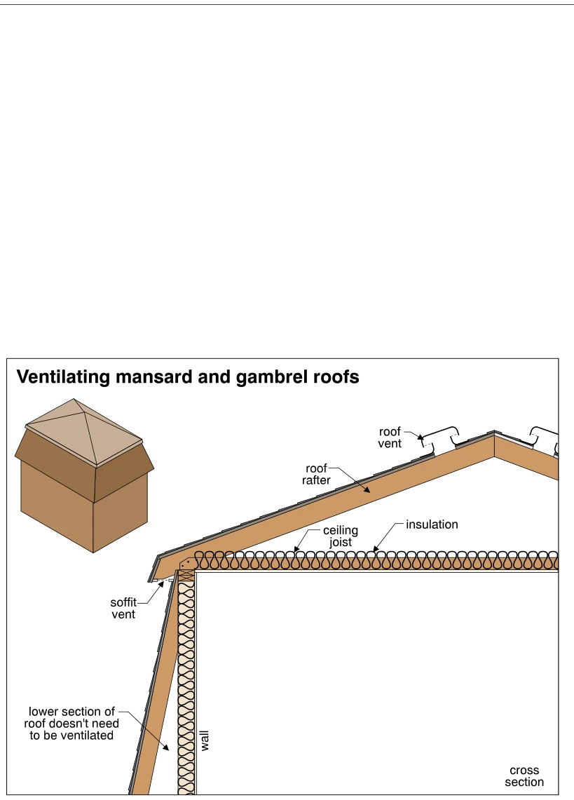
1348Ventilating mansard and gambrel roofs
· p. 242
The illustration shows a small exterior roof-form diagram and a cross section through a mansard or gambrel roof assembly. The shallow upper roof encloses an attic above insulated ceiling joists, with soffit ventilation at the transition to the steep lower roof and roof vents near the ridge. Insulation continues down the vertical wall behind the steep lower roof section. An annotation states that the lower section of roof does not need to be ventilated.
 1349
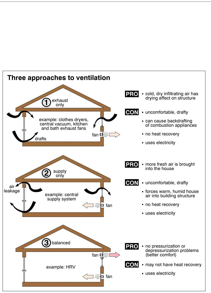
1349Three approaches to ventilation
· p. 242
Three schematic house sections compare exhaust-only, supply-only, and balanced ventilation, with airflow arrows and lists of advantages and disadvantages. Exhaust-only ventilation uses an outward-blowing fan and draws replacement air through envelope leakage paths; the annotations identify drafts and possible combustion-appliance backdrafting. Supply-only ventilation uses an inward-blowing fan and pushes indoor air outward through leakage paths, potentially forcing warm, humid air into the building structure. Balanced ventilation shows separate supply and exhaust fans, names an HRV as an example, and notes the absence of pressurization or depressurization problems. All three approaches are identified as using electricity, and the notes distinguish their heat-recovery limitations.
 1350
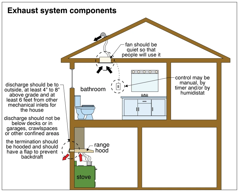
1350Exhaust system components
· p. 242
A house section illustrates a bathroom exhaust fan ducted through the roof and a kitchen range hood discharging through an exterior wall. Arrows show bathroom air entering the ceiling fan and cooking exhaust moving through the range hood to the outdoors. The bathroom fan is linked to a wall control, with annotations recommending quiet operation and manual, timer, or humidistat control. Notes specify outdoor discharge clearances, prohibit discharge into confined areas or below decks, and call for a hooded termination with a backdraft flap.
 1351
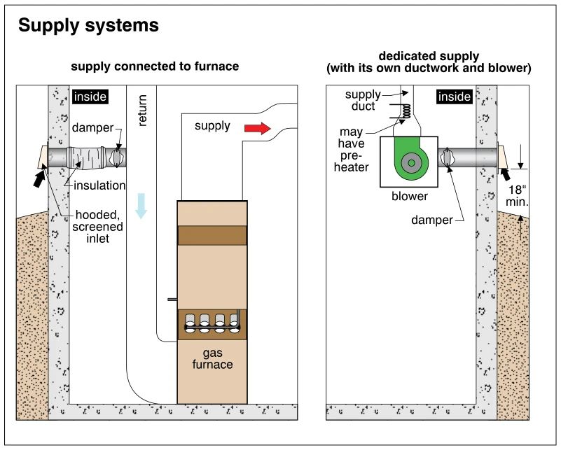
1351Supply systems
· p. 242
The illustration shows two fresh-air supply arrangements for house ventilation. On the left, a hooded, screened outdoor inlet connects through an insulated duct and damper to the return duct of a gas furnace; arrows indicate airflow down the return and out through the supply duct. On the right, a dedicated system draws outdoor air through a wall inlet and damper into its own blower and supply duct. An optional pre-heater is indicated above the blower, and the outdoor inlet is shown at least 18 inches above grade.
 1352
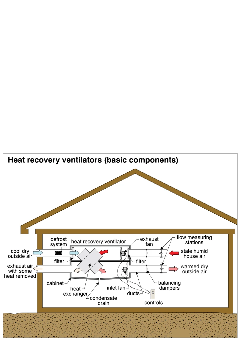
1352Heat recovery ventilators (basic components)
· p. 243
A schematic house contains a heat recovery ventilator connected to outdoor and indoor air ducts. Arrows show cold, dry outside air entering the unit and being delivered indoors as warmed, dry air, while stale, humid house air passes through the unit and is exhausted outside with some heat removed. The cabinet contains a heat exchanger, filters, an exhaust fan, and an inlet fan, with a condensate drain below and a defrost system at the outdoor-air inlet. The indoor-side ducts include balancing dampers and flow measuring stations, and a separate control is connected to the unit. This is an informational diagram of HRV components and airflow, with no defects indicated.
 1353
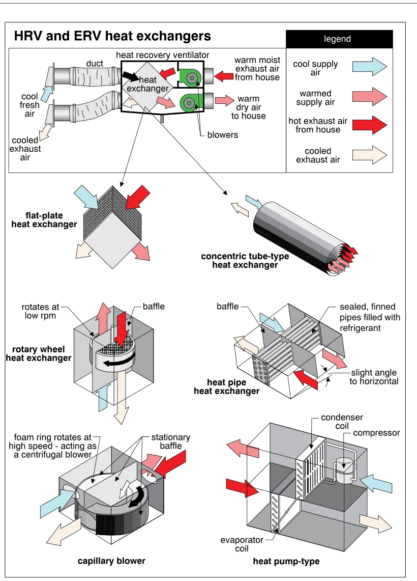
1353HRV and ERV heat exchangers
· p. 243
The illustration shows a ducted heat recovery ventilator with two blowers and a heat exchanger transferring heat from warm house exhaust air to incoming cool fresh air. Color-coded arrows distinguish cool supply air, warmed supply air, hot exhaust air, and cooled exhaust air. Six exchanger arrangements are illustrated: flat-plate, concentric tube-type, rotary wheel, heat pipe, capillary blower, and heat pump-type. The rotary wheel and capillary blower diagrams show rotating elements and baffles, while the heat pipe diagram shows sealed, finned refrigerant-filled pipes set at a slight angle to horizontal. The heat pump-type arrangement identifies an evaporator coil, condenser coil, and compressor.
 1354
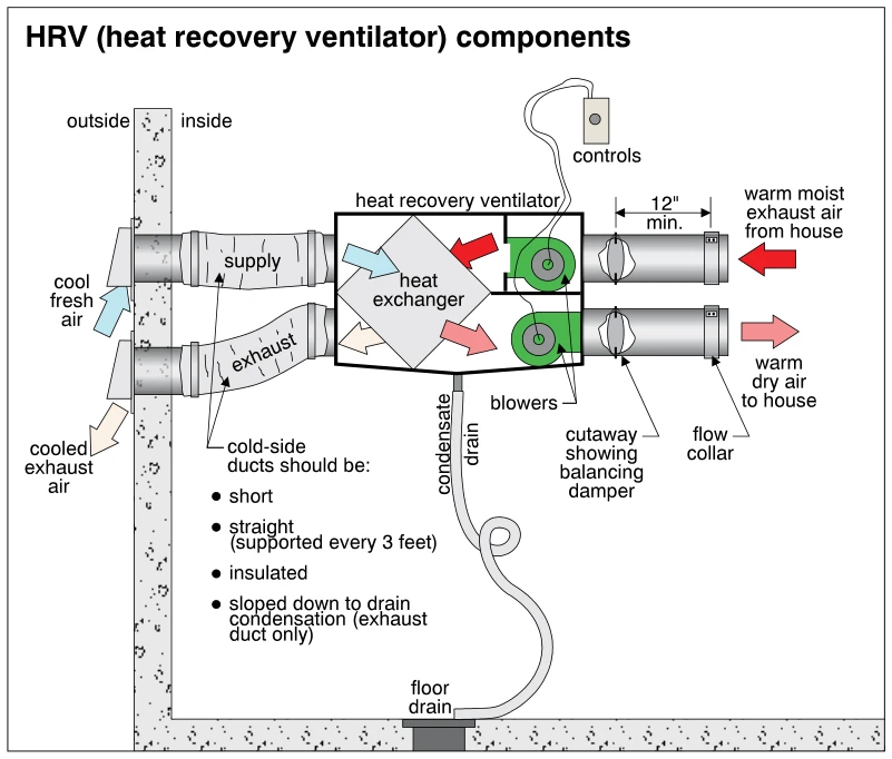
1354HRV (heat recovery ventilator) components
· p. 243
The schematic shows a heat recovery ventilator connected through an exterior wall to fresh-air intake and exhaust ducts, with two additional ducts serving the house. Arrows show cool fresh air passing through the heat exchanger and being supplied to the house as warm dry air, while warm moist house air transfers heat and exits as cooled exhaust air. The cabinet contains a heat exchanger and two blowers connected to controls. House-side ducts include balancing dampers and flow collars, with a 12-inch minimum dimension indicated between them. A condensate drain runs from the cabinet through a loop to a floor drain, and annotations specify short, straight, insulated cold-side ducts, supported every 3 feet, with the exhaust duct sloped to drain condensation.
 1355
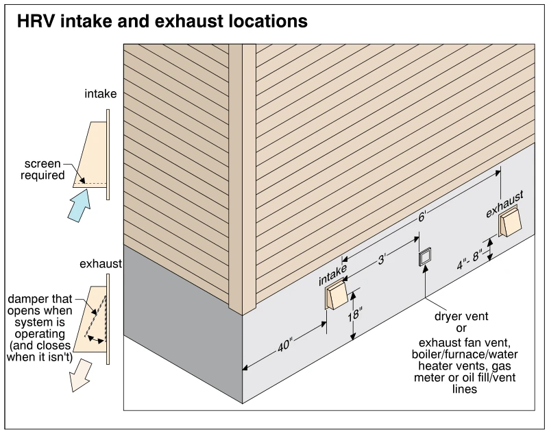
1355HRV intake and exhaust locations
· p. 243
The illustration shows exterior intake and exhaust locations for a heat recovery ventilator on a house wall. Dimension arrows place the intake 40 inches from the building corner and 18 inches above the bottom reference line, with 6 feet between the intake and HRV exhaust. A separate vent or utility location is shown 3 feet from the intake, and the HRV exhaust is marked 4–8 inches above the bottom reference line. Side-view details show a required screen at the intake and an exhaust damper that opens during operation and closes when the system is off. Airflow arrows indicate air entering the intake and leaving the exhaust.
 1356
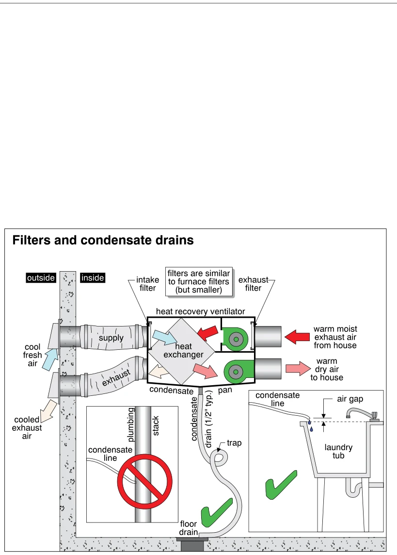
1356Filters and condensate drains
· p. 244
The illustration shows a heat recovery ventilator with intake and exhaust filters, a heat exchanger, fans, and separate supply and exhaust ducts passing through an exterior wall. Colored arrows trace cool outdoor air becoming warm supply air and warm, moist house air becoming cooled exhaust air. A condensate pan beneath the heat exchanger drains through a line with a loop trap to a floor drain, marked with a green check. An alternative approved arrangement discharges the condensate line above a laundry tub with an air gap. An inset marked with a prohibition symbol shows an improper direct condensate connection to a plumbing stack.
 1357
1357Defrost control
· p. 244
Four schematic diagrams illustrate heat recovery ventilator (HRV) defrost-control strategies, with exterior intake and exhaust openings, a heat exchanger, two fans, and arrows indicating airflow. The first arrangement preheats incoming outdoor air with an electric duct heater before it reaches the heat exchanger. The second closes both outdoor-air dampers and recirculates exhaust air through the exchanger. The third shuts off the exhaust fan and closes the fresh-air intake while routing warm house air through the exchanger. The fourth shuts off the fresh-air fan while the exhaust fan continues moving house air through the exchanger to the exterior.
 1357.3
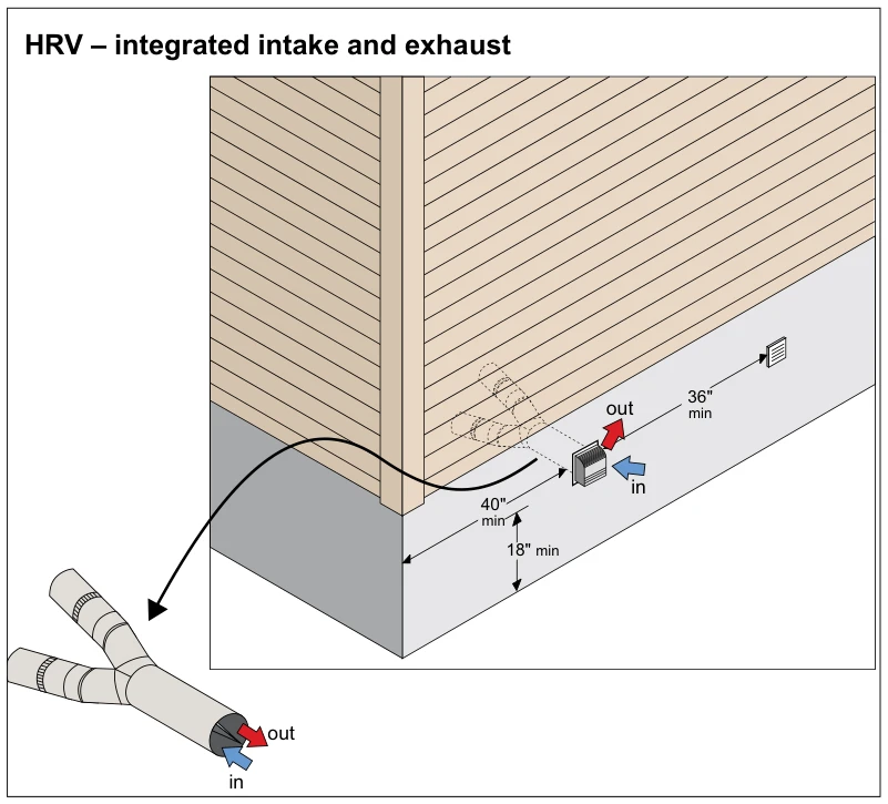
HRV – integrated intake and exhaust
· p. 244
The illustration shows an integrated heat recovery ventilator (HRV) intake and exhaust terminal on an exterior wall near a building corner. Red and blue arrows identify outgoing exhaust air and incoming outdoor air through the shared terminal. Dimension arrows indicate minimum clearances of 40 inches from the corner, 18 inches above the bottom of the wall, and 36 inches from a separate wall vent. An enlarged detail shows two ducts joining a divided common termination that keeps the intake and exhaust airflow paths separate.
 1357.6
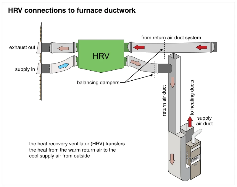
HRV connections to furnace ductwork
· p. 244
The illustration shows a heat recovery ventilator (HRV) connected to furnace ductwork and to outdoor intake and exhaust openings through an exterior wall. Arrows show warm air from the return air duct system entering the HRV and exhaust air leaving outdoors. Outdoor supply air passes through the HRV and enters the furnace return air duct, while the furnace supply air duct carries air toward the heating ducts. Balancing dampers are identified in the two ducts connecting the HRV to the indoor duct system. An annotation explains that the HRV transfers heat from warm return air to cool outdoor supply air.
Atticsp. 245
 1357.9
HRV – attic insulation
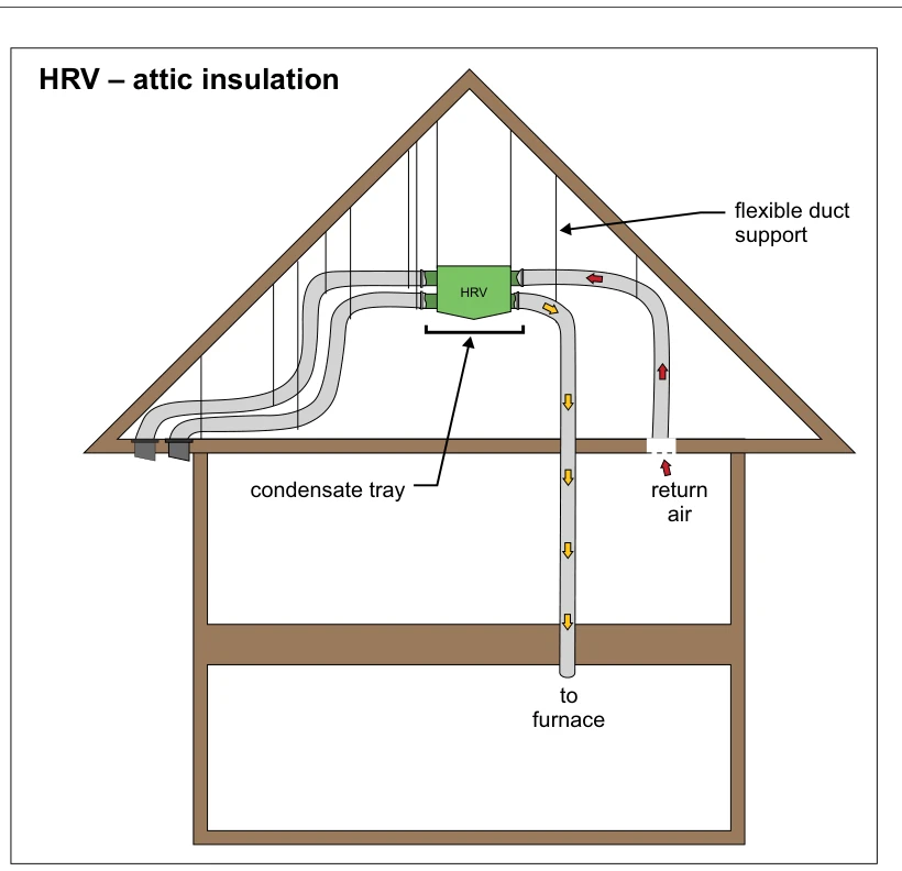
· p. 245
A house cross-section shows a heat recovery ventilator (HRV) located in a gable attic with flexible ducts connected on both sides. Vertical supports suspend the ductwork from the roof framing, and a condensate tray is positioned beneath the HRV. Two ducts extend to openings at the left eave. Arrows show return air moving upward into the HRV through the right-hand duct and air leaving the HRV through a separate duct descending toward the furnace. Although the title references attic insulation, no distinct insulation layer or insulation defect is illustrated.
 1358
1358Attic access hatch
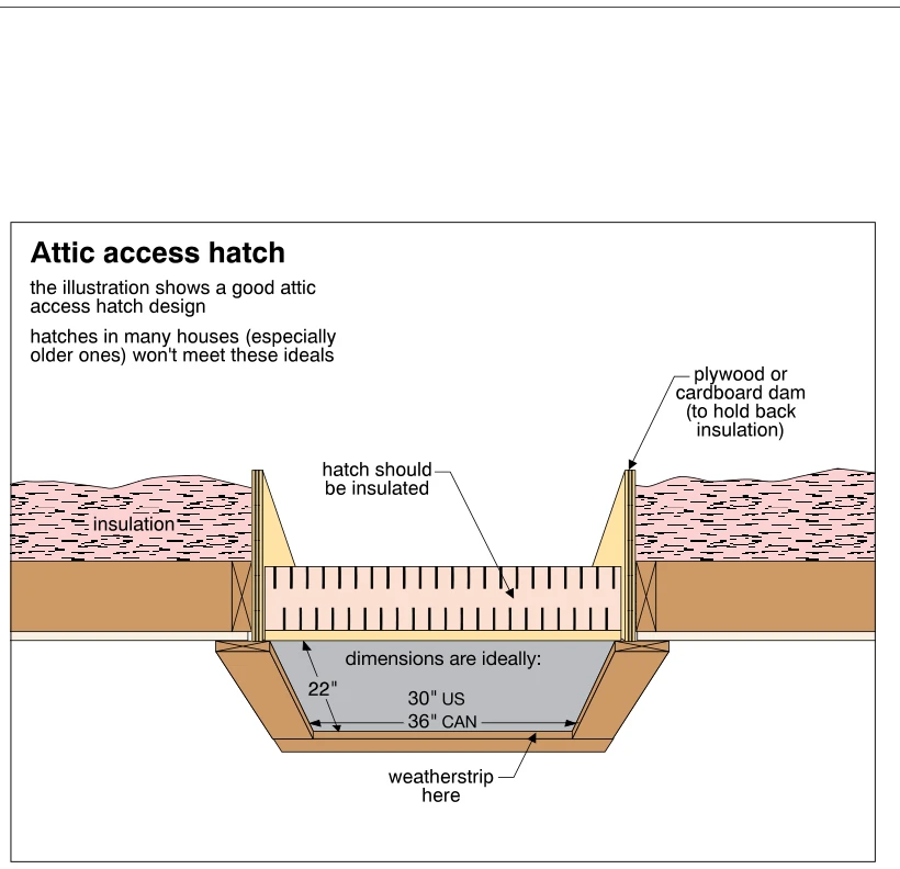
· p. 245
The illustration shows a cutaway of a recommended attic access hatch within an insulated ceiling. The hatch has insulation above its panel and rests on trim around the opening, with weatherstripping indicated at the seating surface. Upright plywood or cardboard dams around the opening hold back the adjacent attic insulation. The ideal opening dimensions are labeled as 22 inches by 30 inches in the US or 22 inches by 36 inches in Canada. A note states that hatches in many houses, especially older ones, will not meet these ideals.
 1359
1359Stairwells to attic
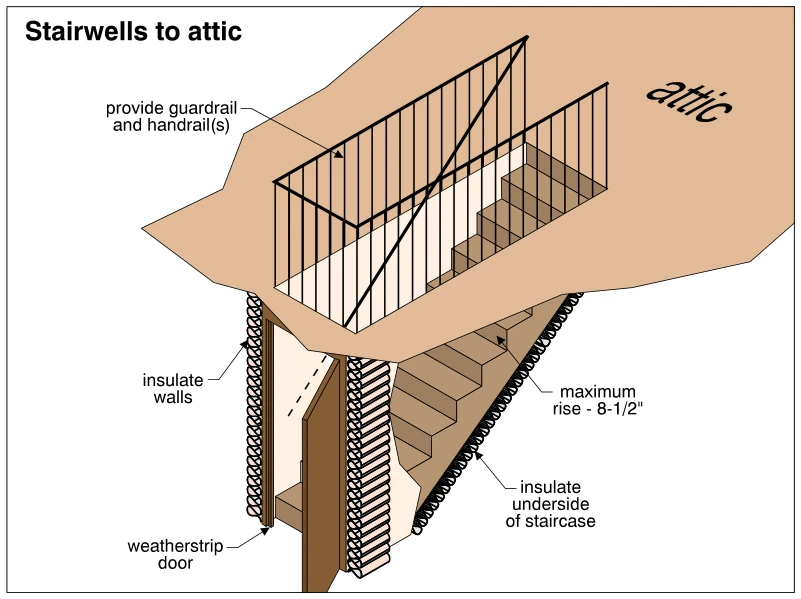
· p. 245
The illustration shows an enclosed staircase leading through an attic floor opening, with a door at the lower entrance. Insulation is indicated along the stairwell walls and beneath the staircase, and the entrance door is identified for weatherstripping. Guardrails surround the exposed attic stair opening, with a callout to provide guardrails and handrails. A stair annotation specifies a maximum rise of 8-1/2 inches.
 1360
1360Pull-down stairs
· p. 245
Three cross-sectional views show pull-down attic stairs in stored, partially lowered, and extended positions. View A shows the folded stairs beneath an insulated cover spanning the attic access opening, with insulation on either side. Views B and C use curved arrows to illustrate lowering the assembly and unfolding the hinged stair section. An annotation identifies the access as a potential source of heat loss and air leakage into the attic and recommends an insulated cover. A warning notes the risk of injury when operating or using the stairs, and the drawing states that springs and the handrail are not shown.
 1361
1361Secondary attics
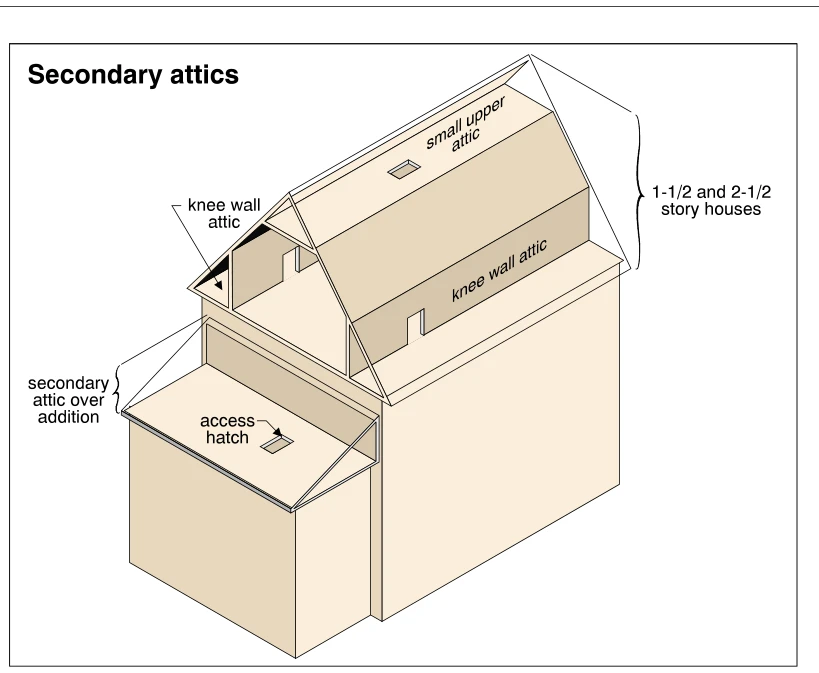
· p. 246
A cutaway house diagram shows secondary attic spaces in a 1-1/2- or 2-1/2-story house with an addition. Knee wall attics lie along the low sides of the steeply pitched main roof, outside the knee walls enclosing the upper living space. A small upper attic sits above the upper-story ceiling near the roof ridge. A separate secondary attic is shown over the lower addition, with a labeled access hatch in its floor. Additional access openings are illustrated in the knee walls and upper ceiling; no insulation installation or defects are depicted.
 1362
1362Risks of adding more insulation
· p. 246
A section through an attic eave shows new insulation added over old insulation above the ceiling, beside an exterior wall and beneath a sloping roof. The added insulation obstructs the soffit vents, and a separate warning identifies insufficient attic ventilation. A metal chimney passes through the ceiling insulation and roof, with insulation shown too close to the chimney. A recessed ceiling light is buried in the insulation. Red crosses identify these improper conditions.
 1363
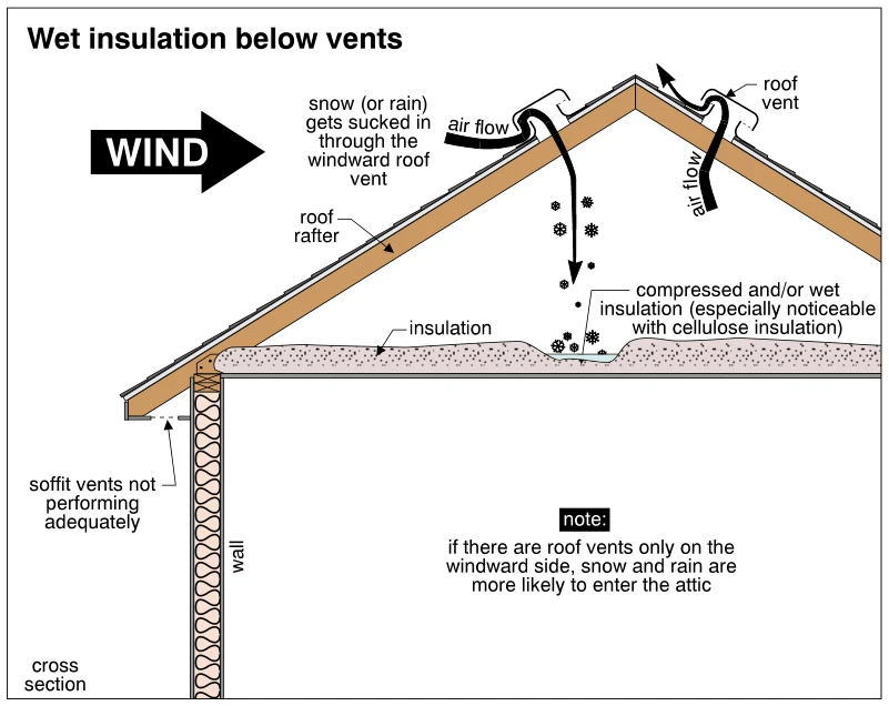
1363Wet insulation below vents
· p. 246
The cross section shows an attic beneath a pitched roof, with roof vents on both slopes and insulation over the ceiling. Wind and airflow arrows show snow or rain being drawn through the windward roof vent and falling onto the attic insulation, while air exits through the opposite vent. A depressed area beneath the entry point is labeled as compressed and/or wet insulation, especially noticeable with cellulose insulation. The soffit vents at the illustrated eave are identified as not performing adequately. A note explains that snow and rain are more likely to enter when roof vents are located only on the windward side.
 1364
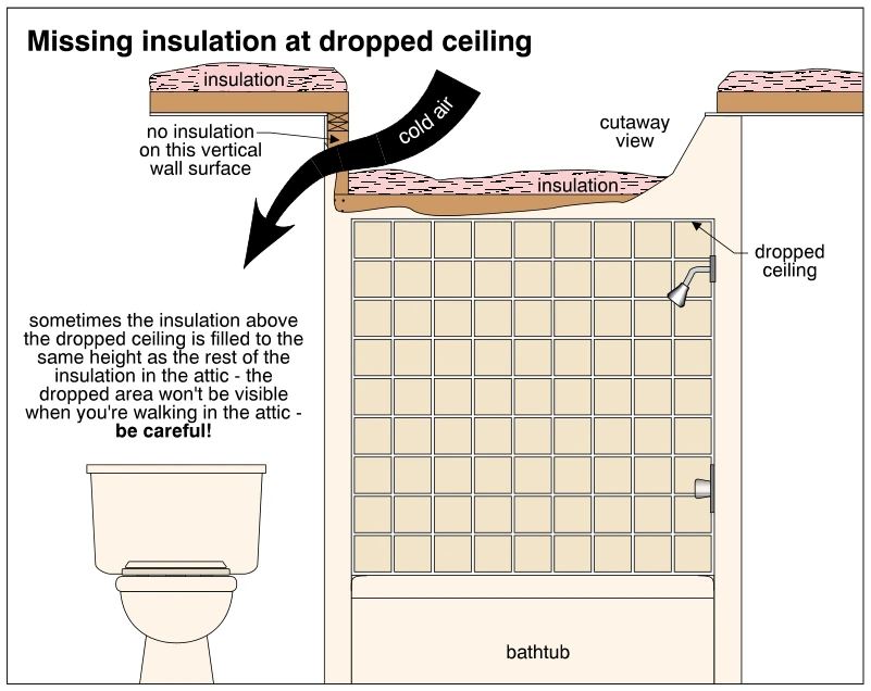
1364Missing insulation at dropped ceiling
· p. 246
A cutaway bathroom illustration shows a dropped ceiling above a bathtub and tiled shower enclosure, with attic insulation on the horizontal ceiling surfaces. The vertical transition between the higher ceiling and the dropped ceiling is identified as having no insulation. A large arrow labeled cold air points toward this uninsulated transition and down toward the room. An annotation warns that insulation filled to the surrounding attic level can conceal the dropped area, creating a hazard when walking in the attic.
 1365
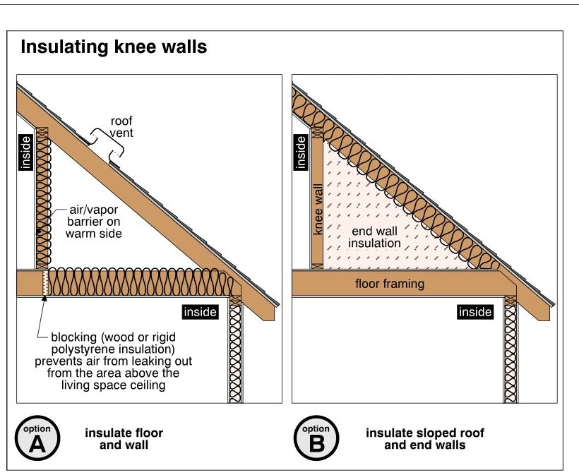
1365Insulating knee walls
· p. 247
Two sectional diagrams compare insulation strategies for the attic space behind a knee wall. Option A places insulation in the knee wall and attic floor, with an air/vapor barrier on the warm side and a roof vent above the attic space. Blocking beneath the knee wall prevents air leakage from the area above the living-space ceiling into the attic. Option B places insulation along the sloped roof and end walls, bringing the space behind the knee wall within the insulated enclosure rather than insulating the knee wall and floor.
 1366
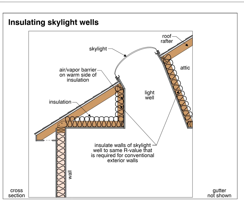
1366Insulating skylight wells
· p. 247
The cross section shows a skylight in a sloped roof with a light well extending through the attic to the space below. Insulation follows the ceiling and the walls of the skylight well, separating the interior from the attic. An air/vapor barrier is indicated on the warm side of the insulation. The annotation specifies insulating the skylight well walls to the same R-value required for conventional exterior walls.
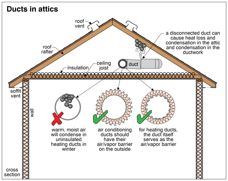 1367
1367Ducts in attics
· p. 247
A house cross section shows ductwork in an attic above insulated ceiling joists, with roof rafters, roof vents, and soffit vents. A disconnected duct is shown releasing moist air, with a warning about heat loss and condensation in the attic and ductwork. Three enlarged duct cross sections compare an uninsulated heating duct marked with a red X against two insulated arrangements marked with green checks. The air-conditioning duct has its air/vapor barrier outside the insulation, while the heating duct itself serves as the air/vapor barrier.
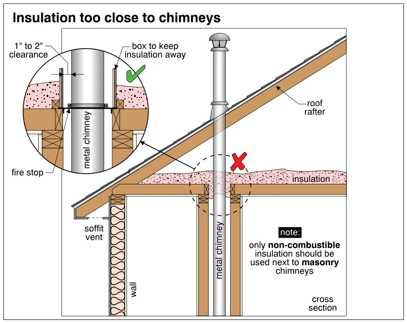 1368
1368Insulation too close to chimneys
· p. 247
The cross section shows a metal chimney passing through an insulated attic floor and a sloping roof near an exterior wall and soffit vent. A red X marks attic insulation placed directly against the chimney. An enlarged detail with a green check shows a box holding insulation away from the metal chimney, with a labeled 1" to 2" clearance and a fire stop at the floor penetration. A separate note states that only non-combustible insulation should be used next to masonry chimneys.
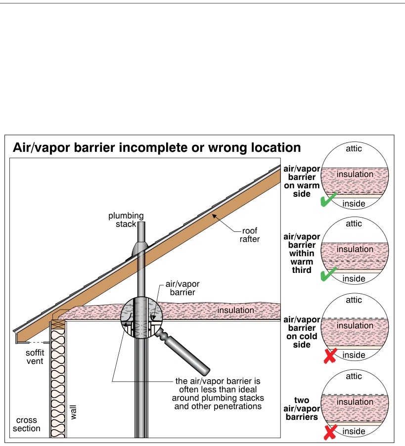 1369
1369Air/vapor barrier incomplete or wrong location
· p. 248
A cross section of an attic eave shows ceiling insulation, an air/vapor barrier beneath it, a roof rafter, a soffit vent, and an insulated exterior wall. A plumbing stack penetrates the ceiling assembly and roof, with a magnified detail highlighting the barrier connection around the stack. An annotation identifies plumbing stacks and other penetrations as locations where the barrier is often less than ideal. Four circular diagrams compare barrier placement relative to the insulation and the attic and interior spaces. Green checks mark placement on the warm side or within the warm third as acceptable, while red crosses mark cold-side placement and two air/vapor barriers as incorrect.
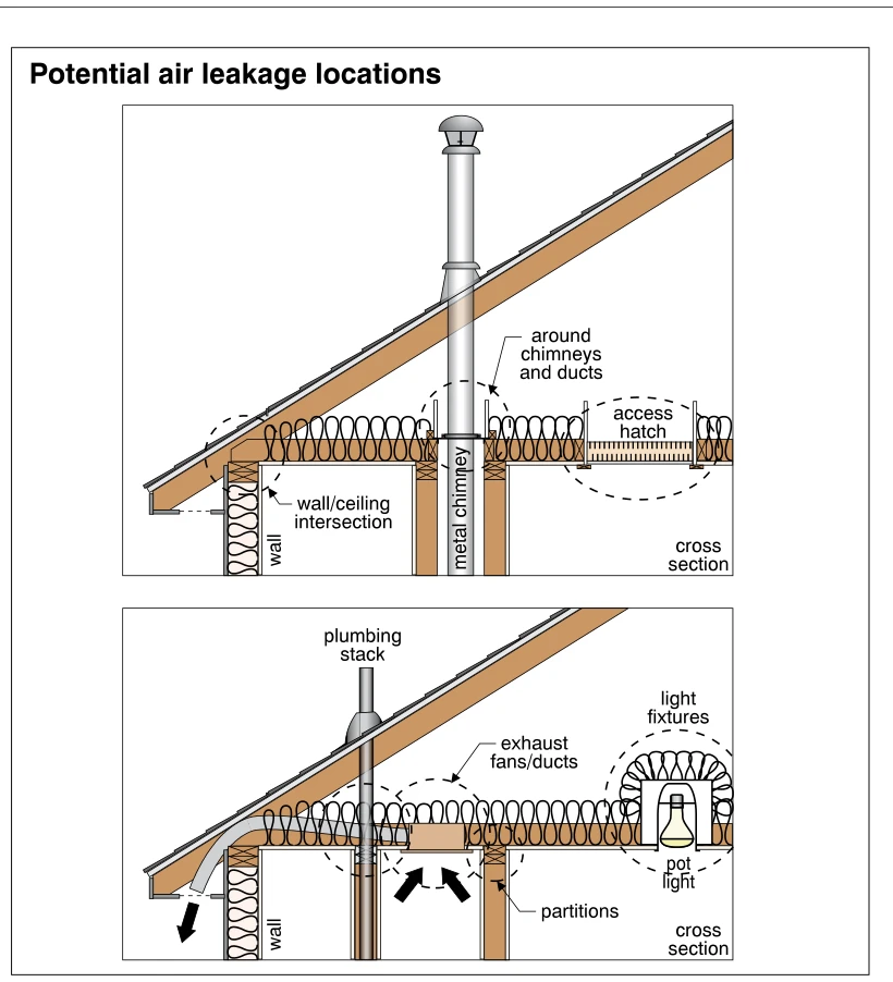 1370
1370Potential air leakage locations
· p. 248
Two cross-sectional drawings show potential air leakage locations between occupied rooms and an insulated attic beneath a sloping roof. The upper drawing highlights the wall/ceiling intersection, the opening around a metal chimney, and an attic access hatch. The lower drawing highlights a plumbing stack penetration, exhaust fans or ducts, partition tops, and a recessed pot light. Dashed outlines identify vulnerable areas, and bold arrows below the exhaust opening indicate upward air movement. Insulation is shown along the attic floor and in the exterior wall, with localized interruptions at penetrations and openings.
 1371
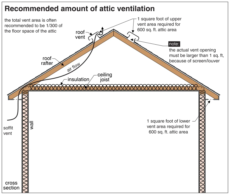
1371Recommended amount of attic ventilation
· p. 248
A cross section of a gable-roofed house shows an insulated attic floor and exterior walls, with soffit vents at the eaves and roof vents near the ridge. Arrows illustrate air entering through a soffit vent, passing through the attic, and exiting through upper roof vents. The diagram recommends total vent area equal to 1/300 of the attic floor area, divided into one square foot of upper vent area and one square foot of lower vent area per 600 square feet of attic. A note explains that actual vent openings must be larger to account for screens or louvers.
 1372
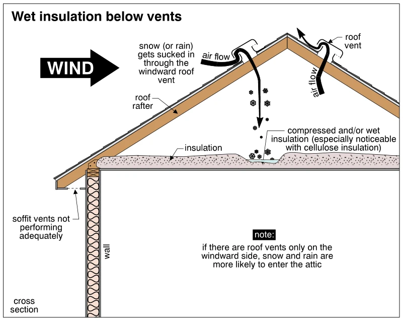
1372Wet insulation below vents
· p. 248
A cross section of a pitched roof and attic shows wind driving snow or rain into a windward roof vent. Airflow arrows show entry through that vent and exhaust through a vent on the opposite roof slope. Precipitation falls onto the attic-floor insulation, where a localized depression is labeled as compressed and/or wet insulation, especially noticeable with cellulose. The soffit vents are identified as not performing adequately. A note warns that snow and rain are more likely to enter the attic if roof vents are located only on the windward side.
 1373
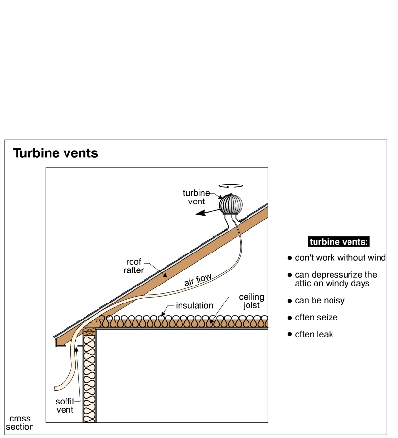
1373Turbine vents
· p. 249
A cross section of a pitched roof and exterior wall shows attic ventilation through a soffit vent and a roof-mounted turbine vent. An airflow path rises from the soffit, passes above the attic-floor insulation, and exits through the turbine vent. A curved arrow above the turbine indicates rotation, while the roof rafter and ceiling joist are identified. Notes list turbine-vent limitations, including dependence on wind, attic depressurization, noise, seizing, and leakage; no specific damaged vent is depicted.
 1374
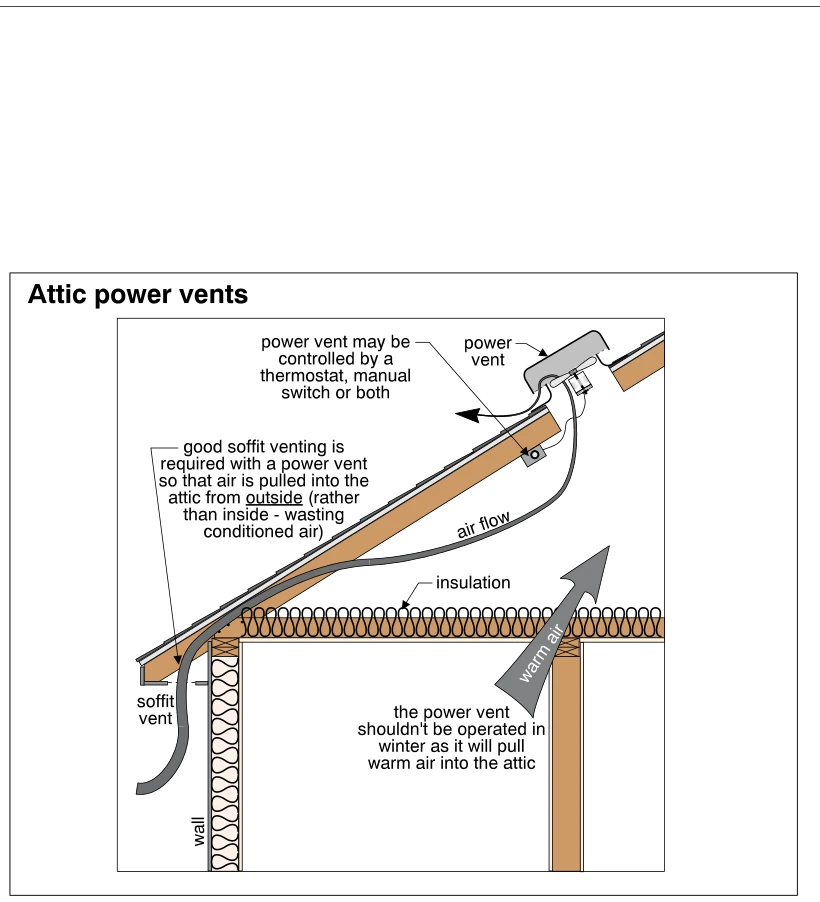
1374Attic power vents
· p. 249
A sectional drawing shows a roof-mounted power vent above an insulated attic floor and exterior wall. An airflow arrow traces outdoor air entering through a soffit vent, passing through the attic, and exhausting through the powered roof vent. A callout identifies thermostat or manual-switch control options. The illustration emphasizes adequate soffit venting to avoid drawing conditioned indoor air into the attic. A second arrow shows warm air rising from the interior, with a warning against operating the power vent in winter.
 1375
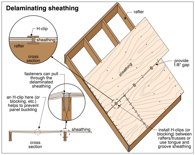
1375Delaminating sheathing
· p. 249
The illustration shows plywood roof sheathing fastened to wood rafters, with H-clips supporting adjoining panel edges between framing members. A callout specifies a 1/8-inch gap between panels and recommends H-clips, blocking, or tongue-and-groove sheathing. Enlarged cross sections show the H-clip connection and separation of plywood layers near fasteners over a rafter. The drawing warns that fasteners can pull through delaminated sheathing and shows how unsupported panel edges can buckle.
 1376
1376Whole house fan with no insulating cover
· p. 249
A cross section shows a ceiling-mounted whole house fan beneath a sloping attic roof, with insulation at the attic floor and in the exterior wall. The fan occupies an opening through the insulated ceiling, with louvers below and a box-shaped insulated cover illustrated above it. Soffit and roof vents are identified along the roof assembly. Although the title refers to a missing insulating cover, the drawing shows the cover's location and explains that without one the fan opening can allow air leakage and heat loss into the attic.
Flat and Cathedral Roofsp. 250
 1377
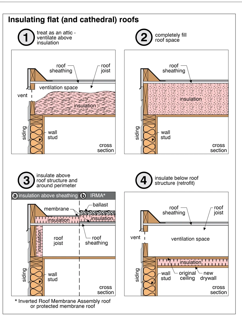
1377Insulating flat (and cathedral) roofs
· p. 250
Four cross-sectional diagrams show alternative insulation arrangements for flat and cathedral roofs at an exterior wall junction. The first places insulation below an open ventilation space connected to an edge vent, while the second completely fills the roof space with insulation beneath the sheathing. The third places insulation above the roof structure and around its perimeter, comparing insulation beneath a roof membrane with an inverted roof membrane assembly that has insulation above the membrane and ballast on top. The fourth illustrates a retrofit with insulation installed below the original ceiling and covered by new drywall, leaving a ventilated roof cavity above. Wood-framed walls, siding, roof sheathing, and roof framing establish the relationship between the roof insulation and the exterior wall.
 1378
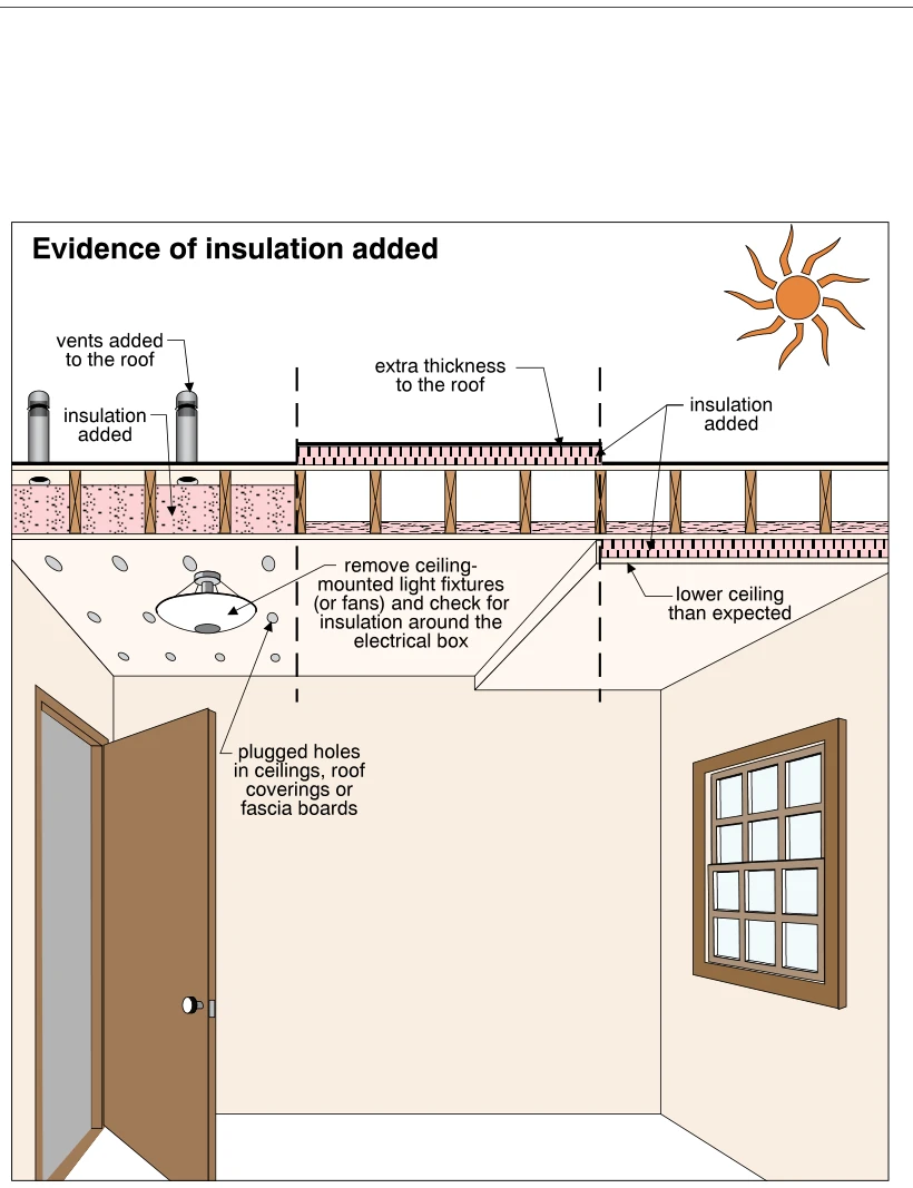
1378Evidence of insulation added
· p. 250
The illustration shows a cutaway flat roof and room ceiling with several possible signs of added insulation. At the left, insulation fills the spaces between wood framing members, roof vents project above the roof, and plugged holes appear in the ceiling. The middle section shows insulation above the roof framing that adds thickness to the roof assembly. At the right, an added insulation layer below the framing lowers the ceiling. An annotation recommends removing ceiling-mounted light fixtures or fans to check for insulation around the electrical box.
 1379
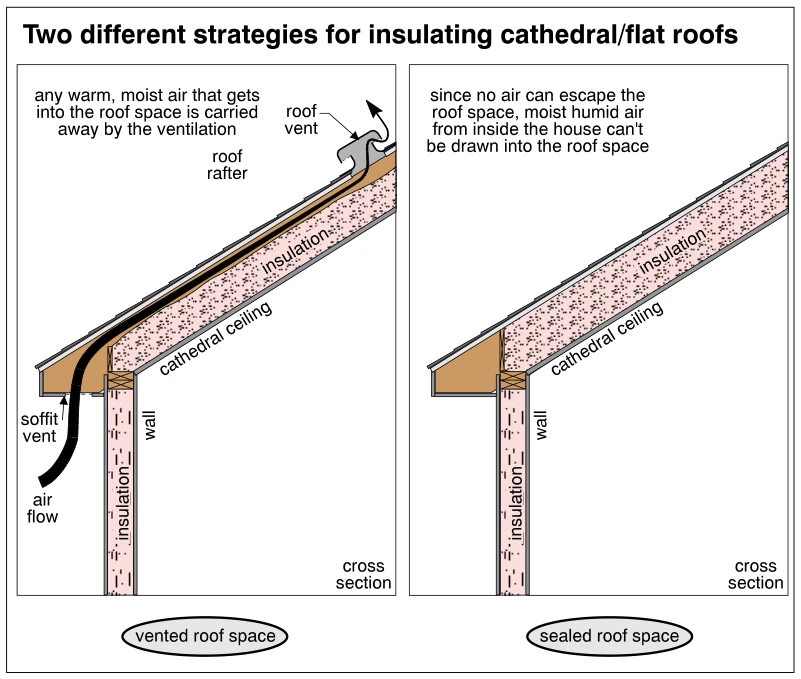
1379Two different strategies for insulating cathedral/flat roofs
· p. 250
Two cross sections compare vented and sealed insulation strategies for cathedral and flat roofs, illustrated with sloping cathedral ceilings above insulated walls. In the vented assembly, an air space separates the roof insulation from the roof deck, and arrows show air entering a soffit vent and exiting through a roof vent. The annotation explains that ventilation carries away warm, moist air entering this space. In the sealed assembly, insulation fills the space between the cathedral ceiling and roof deck, with no ventilation channel or vents shown. Its annotation describes preventing moist indoor air from being drawn into the roof space by eliminating air escape.
 1380
1380Channeled vents versus cross ventilation
· p. 250
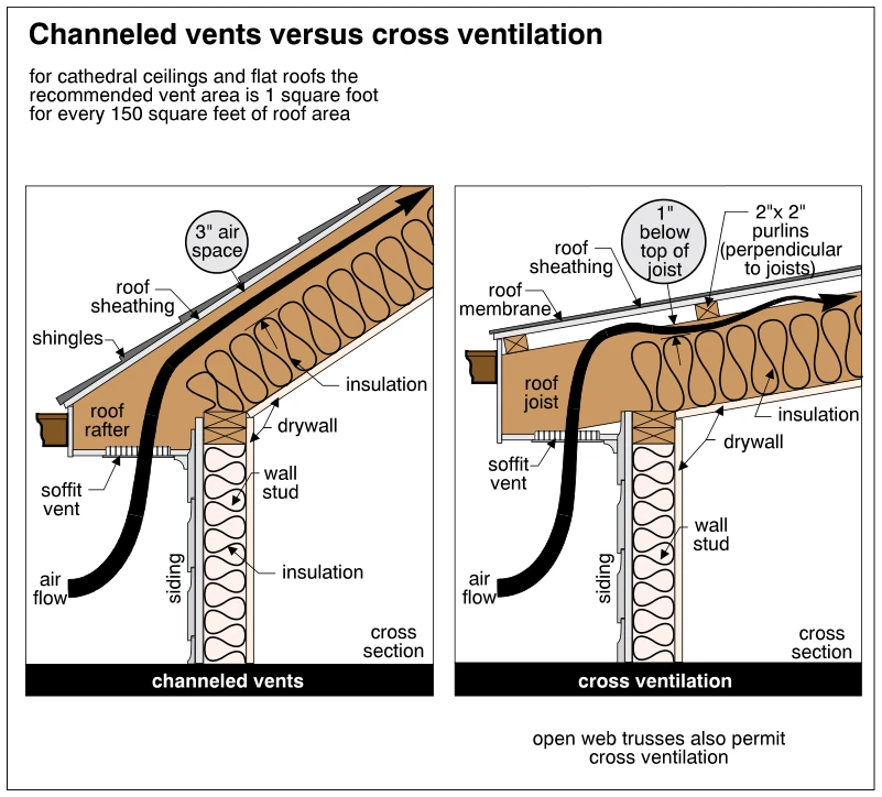
Two roof-to-wall cross sections compare channeled ventilation with cross ventilation for cathedral ceilings and flat roofs. The left drawing shows air entering a soffit vent and traveling up a sloped shingle roof through a labeled 3-inch air space between the insulation and roof sheathing. The right drawing shows a membrane roof with sheathing supported on 2-by-2 purlins perpendicular to the roof joists, with insulation held 1 inch below the joist tops to provide interconnected ventilation space. Both sections show insulated stud walls, siding, and interior drywall, with bold arrows indicating airflow from the soffits into the roof spaces. Notes state a recommended vent area of 1 square foot per 150 square feet of roof area and indicate that open web trusses also permit cross ventilation.
Walls Above Gradep. 251
 1381
1381Insulation short circuit
· p. 251
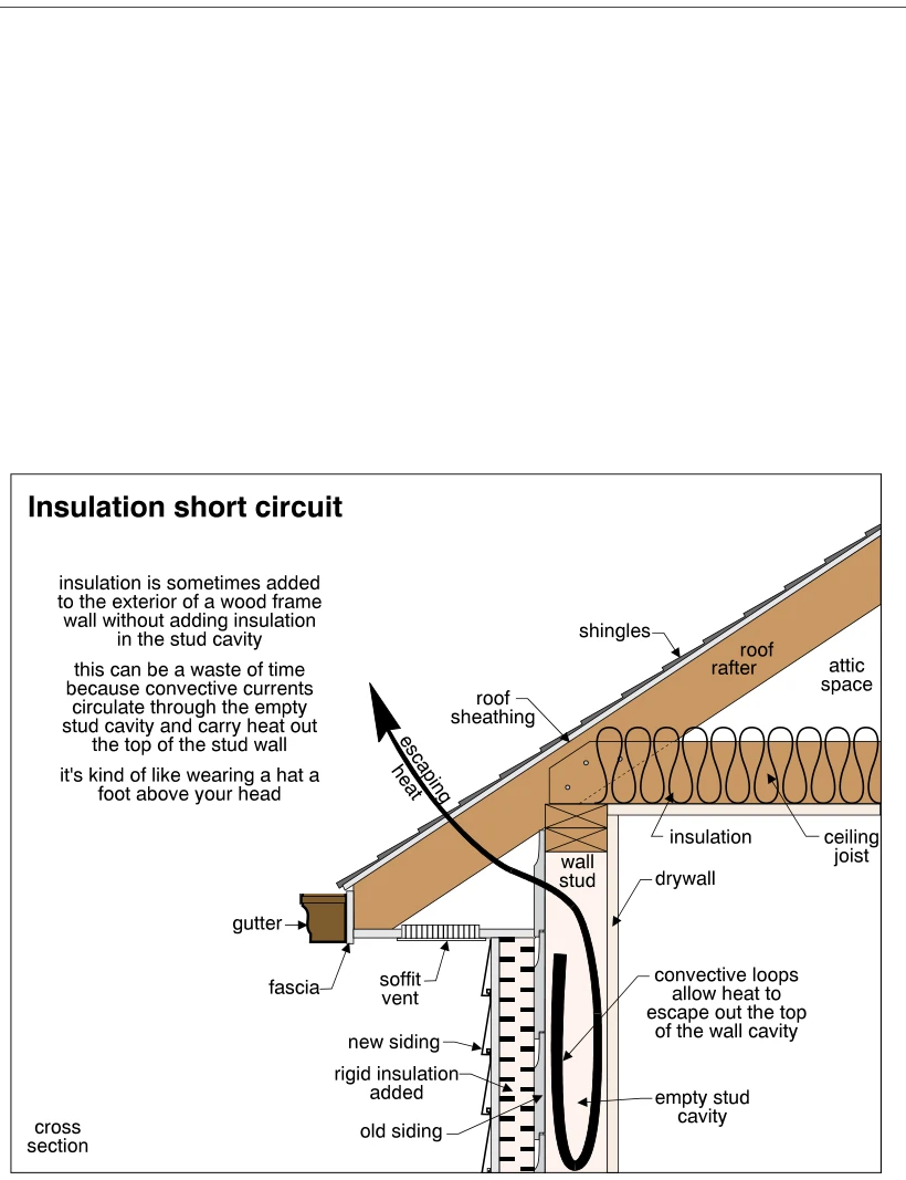
The cross section depicts a wood-frame exterior wall meeting an insulated attic floor and sloped roof at the eave. Rigid insulation and new siding have been added outside the old siding, while the stud cavity remains empty behind the interior drywall. A large looping arrow shows convective circulation within the empty wall cavity and heat escaping at the top of the wall toward the roof. The illustration identifies this as an insulation short circuit that undermines the benefit of the added exterior insulation. Roof shingles, sheathing, a rafter, gutter, fascia, and soffit vent establish the surrounding eave assembly.
 1382
1382Adding insulation to solid masonry walls
· p. 251
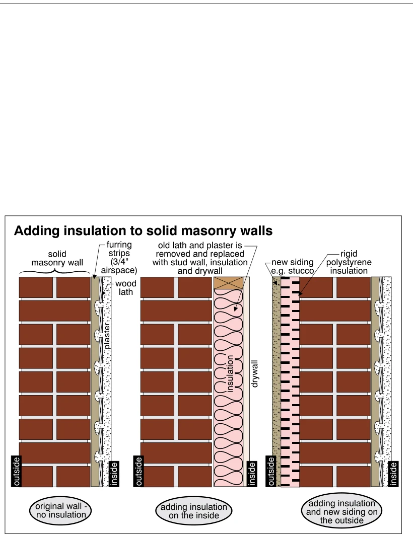
Three wall sections compare an uninsulated solid masonry wall with interior and exterior insulation retrofits. The original wall has interior furring strips providing a 3/4-inch airspace, wood lath, and plaster. The interior retrofit removes the old lath and plaster and replaces them with an insulated stud wall finished with drywall. The exterior retrofit adds rigid polystyrene insulation and new siding, such as stucco, outside the masonry while retaining the interior lath and plaster. Each section identifies the inside and outside faces.
 1383
1383Cold wall effect
· p. 251
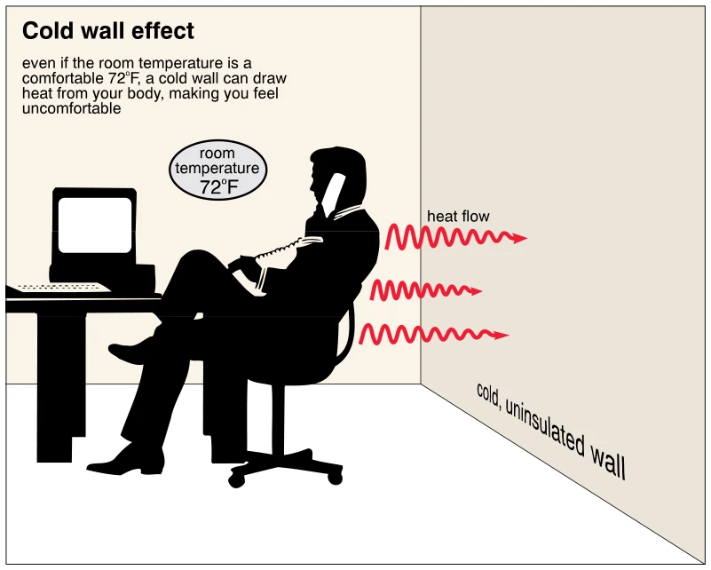
The illustration shows a person seated at a desk beside a cold, uninsulated wall. The room temperature is identified as 72°F. Red wavy arrows indicate heat flow from the person's body toward the cold wall. The diagram explains how radiant heat loss to a cold wall can make an occupant uncomfortable even when the room air temperature is otherwise comfortable.
 1384
1384Drying potential of walls
· p. 251
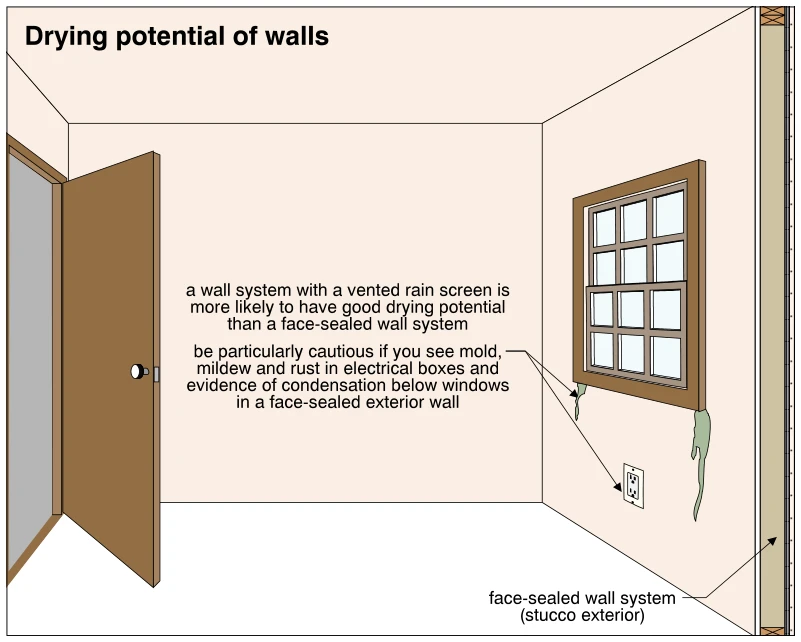
The illustration shows an interior room with a window, an electrical receptacle, and a cutaway at the edge of an exterior wall identified as a face-sealed stucco wall system. Irregular discolored areas extend down the interior wall beneath the window corners. Arrows direct attention to the area below the window and the electrical box as locations to check for moisture-related warning signs. The annotations advise caution when mold, mildew, rust in electrical boxes, or condensation below windows is found in a face-sealed exterior wall. They also explain that a vented rain screen wall generally has better drying potential than a face-sealed wall system.
Basements and Crawlspacesp. 252
 1385
1385Adding exterior basement insulation
· p. 252
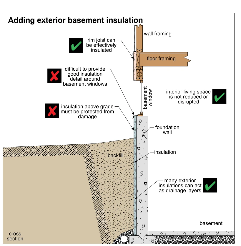
The cross section depicts insulation added to the exterior of a basement foundation wall, extending from the footing area to above grade beside a basement window. Backfill lies outside the insulation, and a drainpipe in aggregate is shown beside the footing. The upper detail shows wood wall and floor framing with insulation at the rim joist. Green check marks identify effective rim-joist insulation, preservation of interior living space, and the potential for exterior insulation to act as a drainage layer. Red crosses highlight the difficulty of detailing insulation around basement windows and the need to protect above-grade insulation from damage.
 1386
1386Adding interior basement insulation
· p. 252
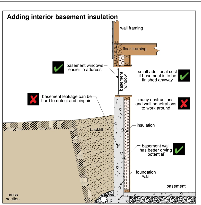
The cross section shows insulation installed in framing on the interior side of a basement foundation wall, with exterior backfill, a footing, and a basement floor slab below. A basement window interrupts the wall above grade, and insulated floor framing and wall framing are shown above it. Green check marks identify easier treatment of basement windows, small additional cost when finishing the basement anyway, and better basement-wall drying potential. Red crosses identify the difficulty of detecting and pinpointing basement leakage and the need to work around obstructions and wall penetrations.
 1387
1387Basement moisture control
· p. 252
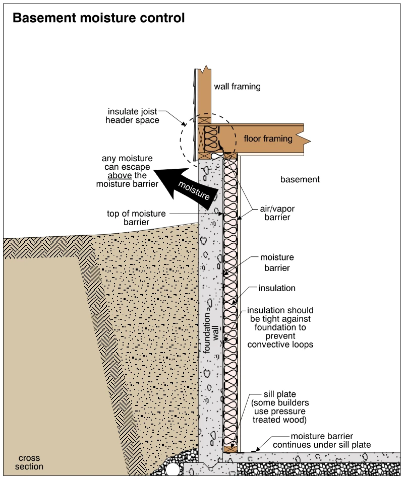
The cross section shows an insulated basement foundation wall, adjacent soil, floor slab, and wood floor and wall framing above. Interior insulation is fitted tightly against the foundation to prevent convective loops, with an air/vapor barrier on the basement side. A moisture barrier between the foundation and insulation terminates above exterior grade and continues beneath the sill plate at the slab. An outward arrow indicates that moisture can escape above the top of the moisture barrier. The joist header space is also shown insulated.
 1388
1388Insulating crawlspaces
· p. 252
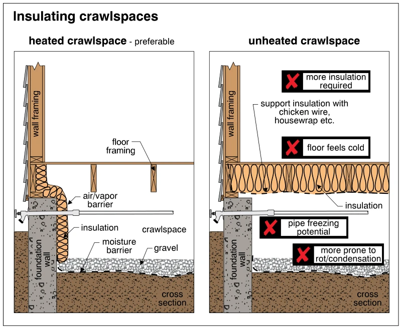
Two cross sections compare insulation strategies for heated and unheated crawlspaces, with the heated crawlspace identified as preferable. In the heated arrangement, insulation and an air/vapor barrier follow the perimeter from the floor edge down the inside of the foundation wall, leaving the floor framing uninsulated. A ground moisture barrier is shown beneath gravel. In the unheated arrangement, insulation fills the floor framing cavities, with a callout specifying support using chicken wire, housewrap, or similar material. Red crosses flag greater insulation requirements, cold floors, potential freezing of the pipe beneath the floor, and increased susceptibility to rot and condensation in the unheated crawlspace.
 1389
1389Clues - has insulation been added?
· p. 253
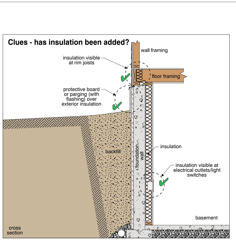
A cross section shows a basement foundation wall, adjacent backfill, and the wall and floor framing above. Insulation is depicted along the interior foundation wall and at the rim joist. Dashed circles and green check marks identify clues that insulation has been added: visible insulation at rim joists, protective board or parging with flashing over exterior insulation, and insulation visible at electrical outlets or light switches. The bottom of the section also shows the foundation footing, basement slab, and an exterior drain pipe in aggregate.
 1390
1390Rim joist insulation
· p. 253
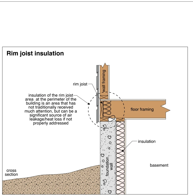
The illustration shows a cross section through the perimeter of a wood-framed floor above a basement foundation wall. Insulation is depicted against the interior face of the foundation wall and in the rim joist area at the edge of the floor framing. A dashed circle highlights the junction between the exterior wall framing, rim joist, and foundation. The annotation identifies this often-overlooked perimeter area as a potential source of air leakage and heat loss if not properly addressed.
 1391
1391Don't insulate embedded joists
· p. 253
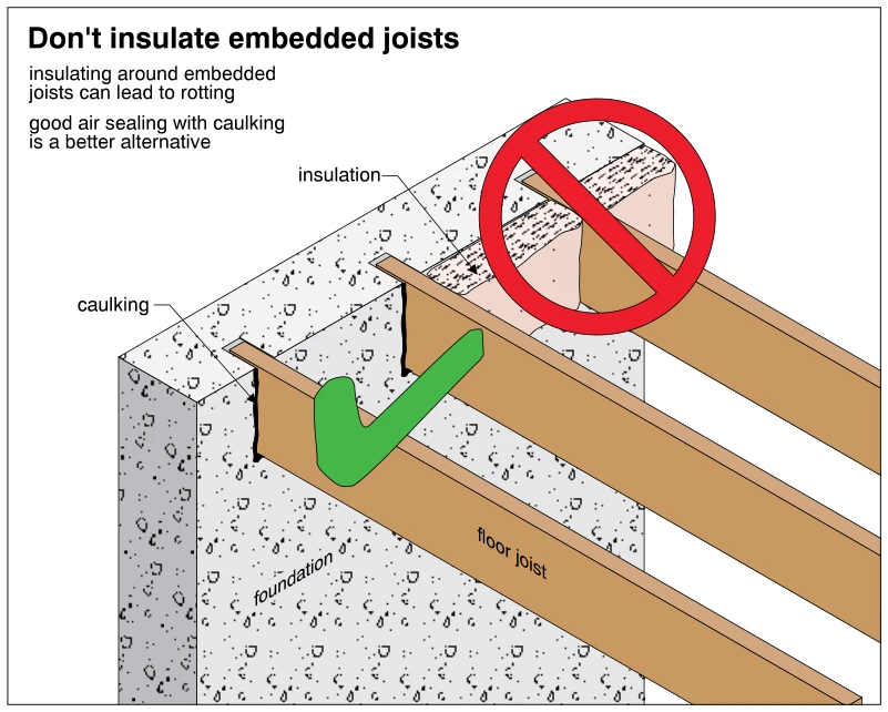
The illustration shows wood floor joists embedded in a solid foundation wall. Insulation placed around the embedded joist ends is marked with a red prohibition symbol, with a warning that this can lead to rotting. Caulking at the joint between the wood and foundation is identified as the preferred air-sealing alternative and marked with a green check. The drawing contrasts insulating the embedded ends with sealing the gaps around them.
 1392
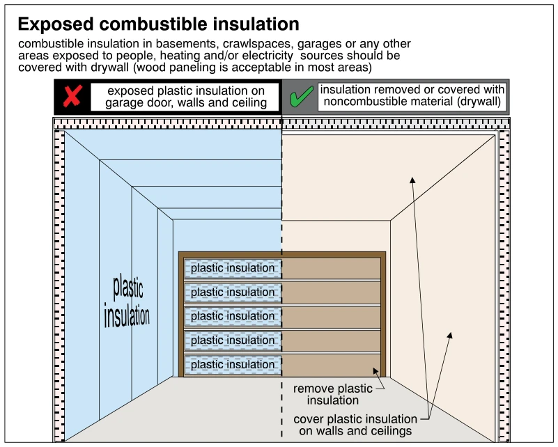
1392Exposed combustible insulation
· p. 253
The illustration compares exposed combustible plastic insulation with corrected conditions in a garage interior. The left half, marked with a red X, shows exposed plastic insulation on the walls, ceiling, and sectional garage door. The right half, marked with a green check, shows the wall and ceiling insulation covered and the plastic insulation removed from the garage door. Arrows identify the door insulation to remove and the wall and ceiling insulation to cover. An introductory note extends the covering guidance to basements, crawlspaces, garages, and other areas exposed to people or heating and electrical sources.
Ventilation Systemsp. 254
 1393
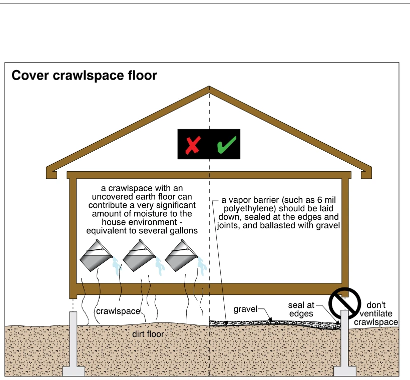
1393Cover crawlspace floor
· p. 254
A house cross-section compares an uncovered crawlspace earth floor on the left with a vapor-barrier-covered floor on the right. A red X, rising wavy lines, and pouring buckets illustrate the significant moisture contribution from exposed soil to the house environment. The right side, marked with a green check, shows a ground vapor barrier sealed at the edges and joints and ballasted with gravel. An annotation recommends a material such as 6 mil polyethylene. A prohibition symbol at the right foundation wall accompanies the instruction not to ventilate the crawlspace.
 1394
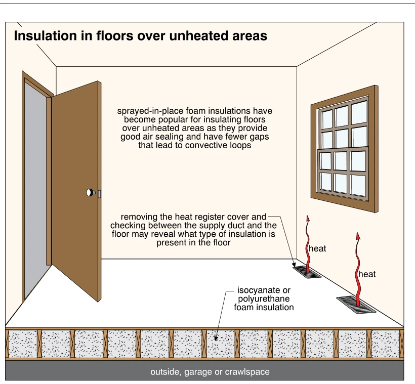
1394Insulation in floors over unheated areas
· p. 254
The illustration shows a heated room above an unheated area, identified as outside, a garage, or a crawlspace. A cutaway along the floor edge shows foam insulation filling the spaces between wood floor joists. Two floor heat registers have upward arrows indicating heat entering the room. An annotation explains that removing a register cover and checking between the supply duct and the floor may reveal the floor insulation type. The drawing notes that sprayed-in-place foam provides air sealing and reduces gaps that can lead to convective loops.
 1395
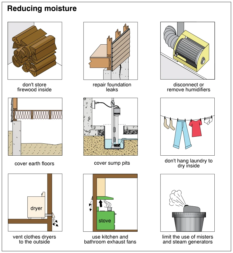
1395Reducing moisture
· p. 254
Nine panels illustrate ways to reduce moisture levels in a home. They address indoor firewood storage, foundation leaks, humidifiers, exposed earth floors, sump pits, and indoor laundry drying. A dryer is shown ducted through an exterior wall, and a stove hood is shown exhausting cooking vapor outdoors. The final panel advises limiting misters and steam generators. The figure combines moisture-source control, foundation repairs, covers over ground and sump openings, and local exhaust ventilation.
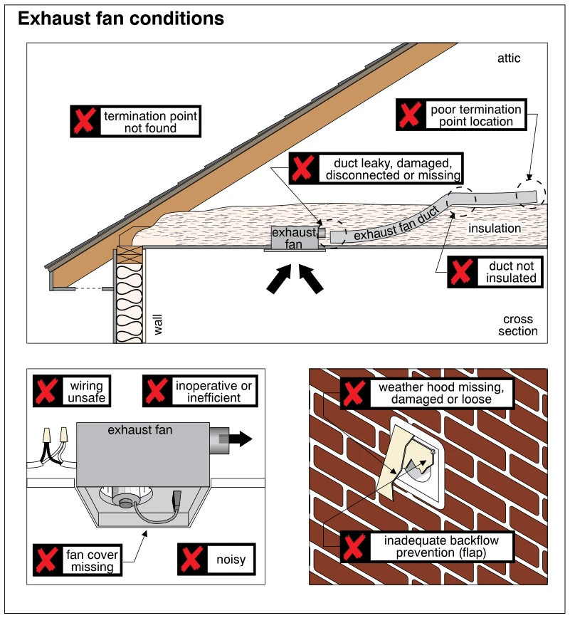 1396
1396Exhaust fan conditions
· p. 254
The upper cross section shows a ceiling-mounted exhaust fan and duct running through attic insulation beneath a sloped roof. Red crosses identify an unlocated termination, a poor termination location within the attic, a leaky or disconnected duct connection, and an uninsulated duct. The lower-left detail shows the fan housing with its cover removed, exposed wiring, and annotations identifying unsafe wiring, ineffective operation, a missing cover, and noise. The lower-right detail shows an exterior exhaust outlet on a brick wall, highlighting weather hood defects and inadequate backflow prevention at the flap.
 1397
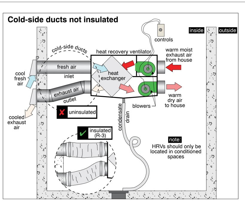
1397Cold-side ducts not insulated
· p. 255
The illustration shows a heat recovery ventilator (HRV) with a heat exchanger, two blowers, controls, and a condensate drain in an interior space. Two cold-side ducts connect the unit to exterior fresh-air intake and exhaust terminations through a wall. Arrows show cool fresh air entering, cooled exhaust air leaving, warm moist house air entering the HRV, and warm dry air returning to the house. The uninsulated cold-side ducts are marked with a red X, while an inset shows the same ducts insulated to R-3 with a green check. A note specifies that HRVs should only be located in conditioned spaces.
 1398
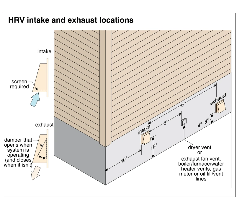
1398HRV intake and exhaust locations
· p. 255
The illustration shows HRV intake and exhaust hoods on the exterior of a house, with dimensioned placement and separation distances. The intake is shown 40 inches from the building corner and 18 inches above the bottom of the wall, with 6 feet separating it from the HRV exhaust. Another wall termination, identified as a possible dryer vent, exhaust fan vent, combustion-appliance vent, gas meter, or oil fill/vent lines, is shown 3 feet from the intake; the exhaust height is marked 4–8 feet. Side-view details show a required screen at the intake and an exhaust damper that opens during operation and closes when the system is off. Arrows indicate air entering the intake and leaving the exhaust.
 1399
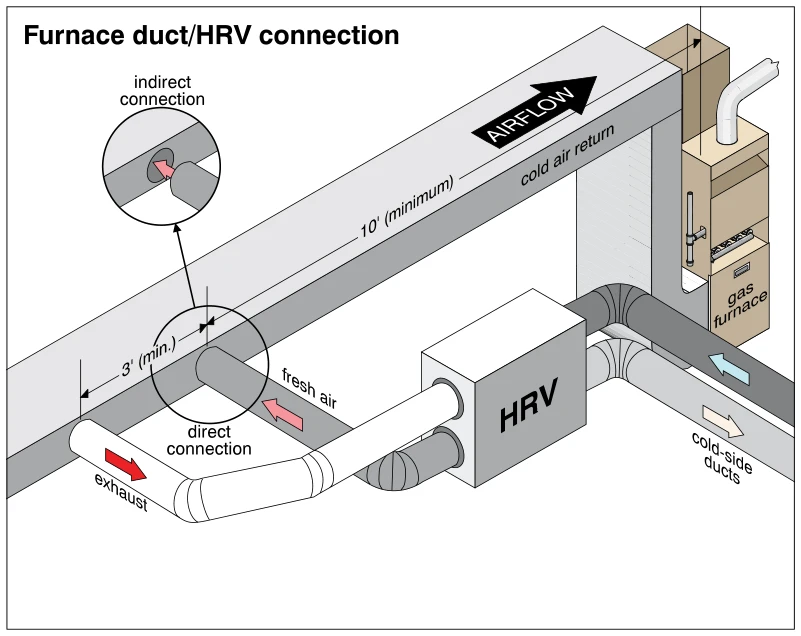
1399Furnace duct/HRV connection
· p. 255
The illustration shows a heat recovery ventilator (HRV) connected to the cold-air return duct of a gas furnace. Arrows show return air moving toward the furnace, fresh air entering the return duct from the HRV, and exhaust air being drawn from the return duct toward the HRV. The exhaust takeoff is shown at least 3 feet upstream of the fresh-air connection, with a minimum 10-foot distance indicated between the fresh-air connection and the furnace end of the return duct. The main drawing shows a direct fresh-air connection, while a circular inset illustrates an indirect connection with a gap between the duct outlet and the return opening. Two additional HRV connections are labeled as cold-side ducts.
 1400
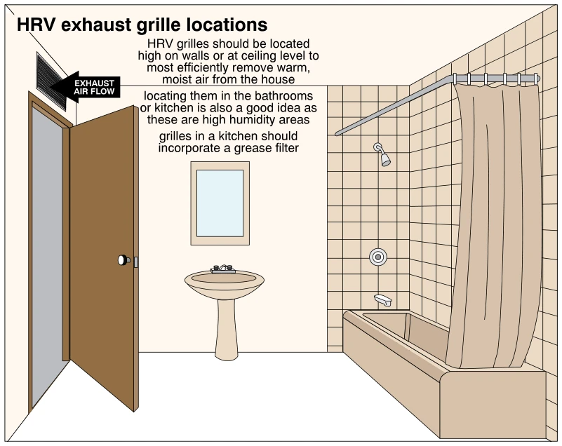
1400HRV exhaust grille locations
· p. 255
The illustration shows a bathroom with an HRV exhaust grille mounted high on the wall above the doorway. An arrow indicates exhaust airflow into the grille. A pedestal sink and a bathtub with shower fixtures and a curtain establish the bathroom setting. The annotations recommend placing HRV exhaust grilles high on walls or at ceiling level to remove warm, moist air, particularly in bathrooms and kitchens. A separate note specifies that kitchen grilles should incorporate a grease filter.
 1401
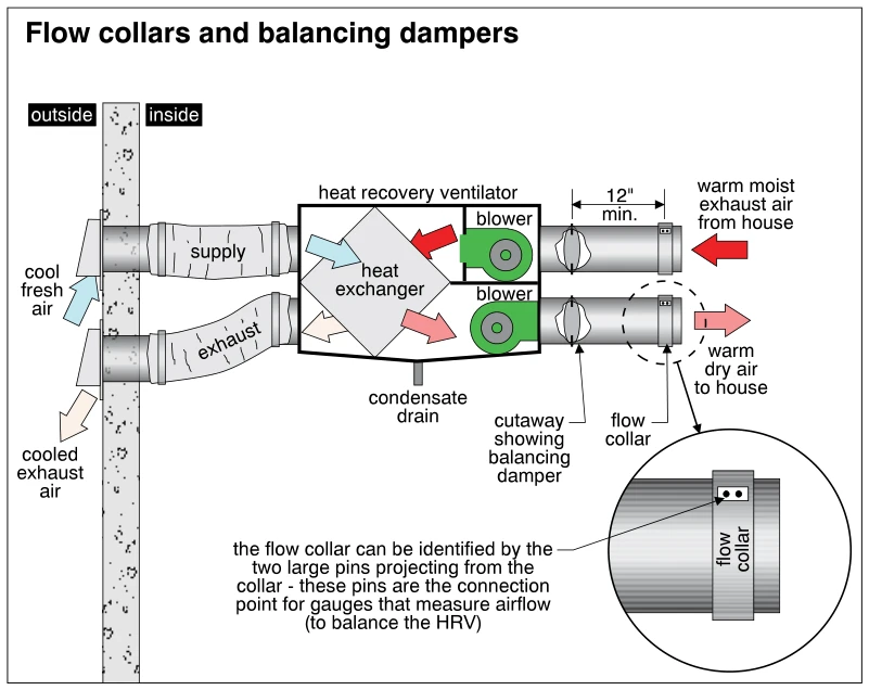
1401Flow collars and balancing dampers
· p. 255
The illustration shows a heat recovery ventilator (HRV) connected to outdoor intake and exhaust ducts and two house-side air ducts. Arrows trace cool fresh air and warm moist house exhaust through a heat exchanger, with separate blowers and a condensate drain shown in the unit. Cutaways in the house-side ducts reveal balancing dampers, and flow collars are located farther along these ducts, with a 12-inch minimum separation indicated on the upper duct. An enlarged detail identifies two projecting pins on a flow collar as gauge connection points for measuring airflow to balance the HRV.
 1402
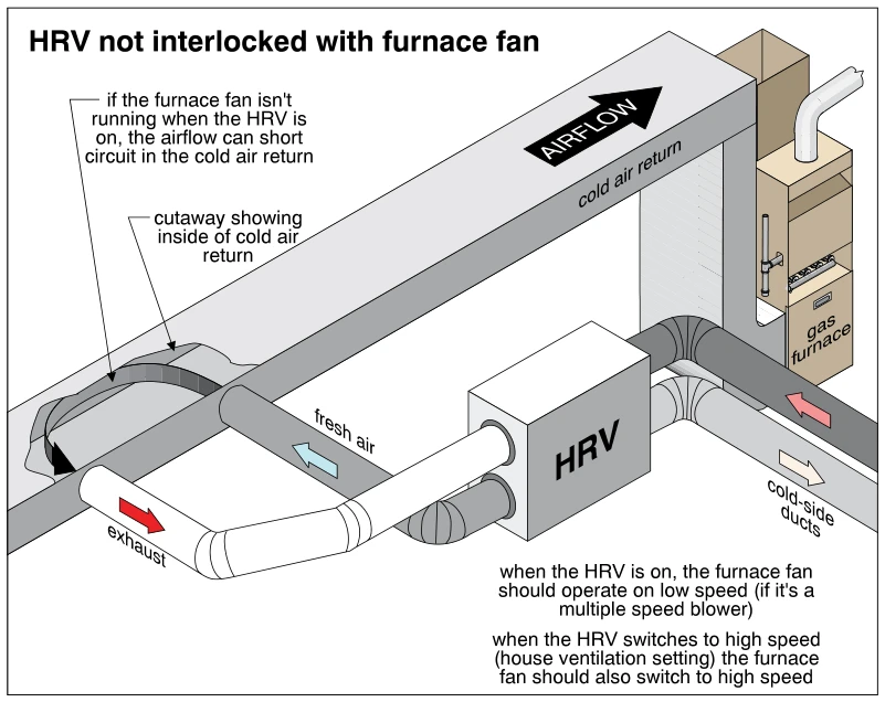
1402HRV not interlocked with furnace fan
· p. 255
The illustration shows a heat recovery ventilator (HRV) connected to the cold-air return duct of a gas furnace, with separate fresh-air and exhaust connections and two cold-side ducts. A cutaway in the return duct shows how airflow can short circuit between the HRV connections when the furnace fan is not running. Arrows indicate airflow through the ducts and toward the furnace. The annotations specify that the furnace fan should run on low speed when the HRV operates, and switch to high speed when the HRV switches to its high-speed house ventilation setting.
 1403
1403Filters dirty or missing
· p. 256
The illustration shows a heat recovery ventilator connected through an exterior wall to fresh-air intake and exhaust ducts. Colored arrows trace cool outdoor air through the heat exchanger toward the house and warm, moist house air through the exchanger toward the outdoor exhaust. Intake and exhaust filters are identified beside the heat exchanger, with two fans shown on the house side of the unit. A condensate pan beneath the exchanger drains through a looped tube to a floor drain. Annotations instruct the inspector to remove the filters to check cleanliness, noting that the dirty side faces away from the heat exchanger and that HRV filters are often neglected; no specific dirt buildup or missing filter is visibly illustrated.
 1404
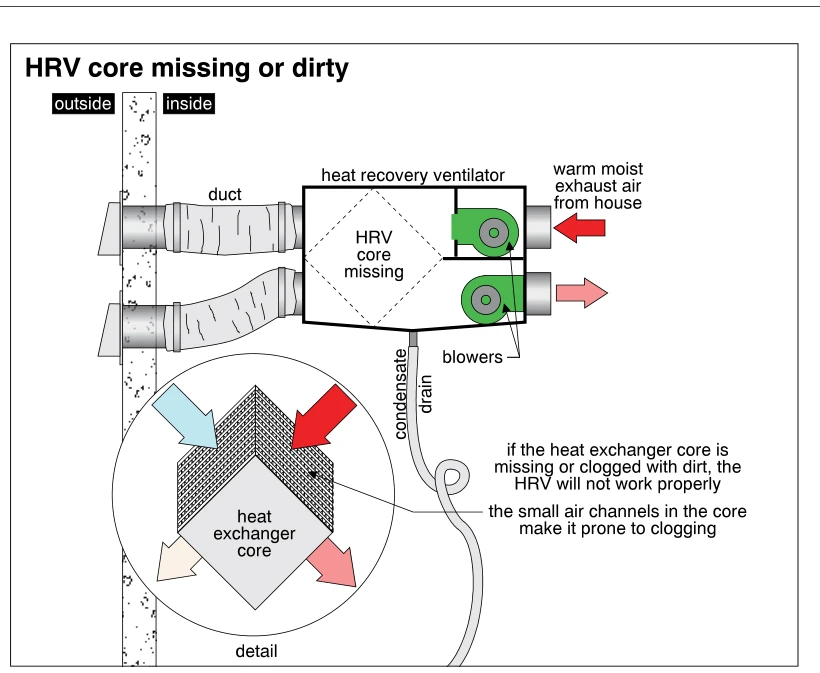
1404HRV core missing or dirty
· p. 256
The illustration shows a heat recovery ventilator connected by two ducts to exterior wall terminations, with two blowers and a condensate drain. A dashed diamond inside the cabinet marks the missing HRV core, and an arrow identifies warm, moist exhaust air entering from the house. An enlarged detail shows the heat exchanger core's closely spaced air channels and colored arrows representing separate airflow paths. Annotations explain that the small channels are prone to clogging and that a missing or dirt-clogged core prevents the HRV from working properly.
 1405
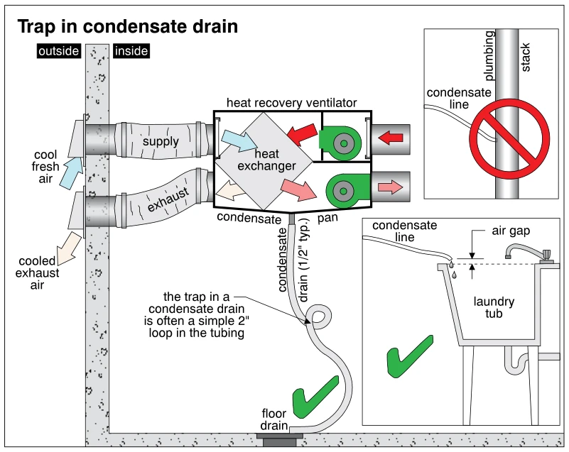
1405Trap in condensate drain
· p. 256
The illustration shows a heat recovery ventilator with a heat exchanger, two fans, and supply and exhaust ducts passing through an exterior wall. A condensate pan beneath the unit drains through tubing labeled as typically 1/2 inch, with a simple 2-inch loop forming a trap. A green check marks discharge to a floor drain. A second approved arrangement shows the condensate line discharging into a laundry tub with an air gap. A crossed-out inset identifies a direct connection of the condensate line to a plumbing stack as improper.