
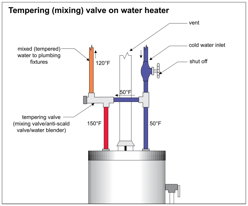
Related illustrations
 1614.4
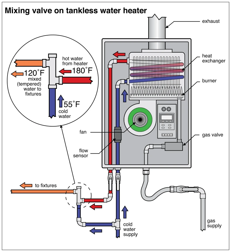
Mixing valve on tankless water heater
· p. 283
The illustration shows a gas-fired tankless water heater with an external mixing valve on its hot-water outlet. Cold supply water branches to both the heater inlet and the mixing valve, where it blends with hot water bef
 1610.1
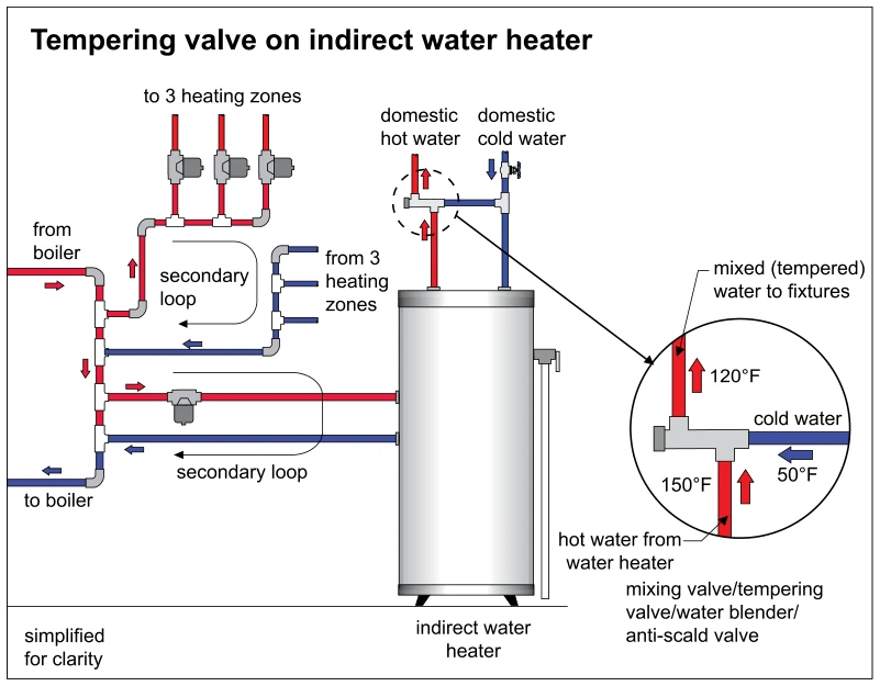
Tempering valve on indirect water heater
· p. 282
The schematic depicts an indirect water heater connected to a boiler system with separate secondary loops for the water heater and three space-heating zones. Red and blue piping and arrows indicate supply and return flow
 0899
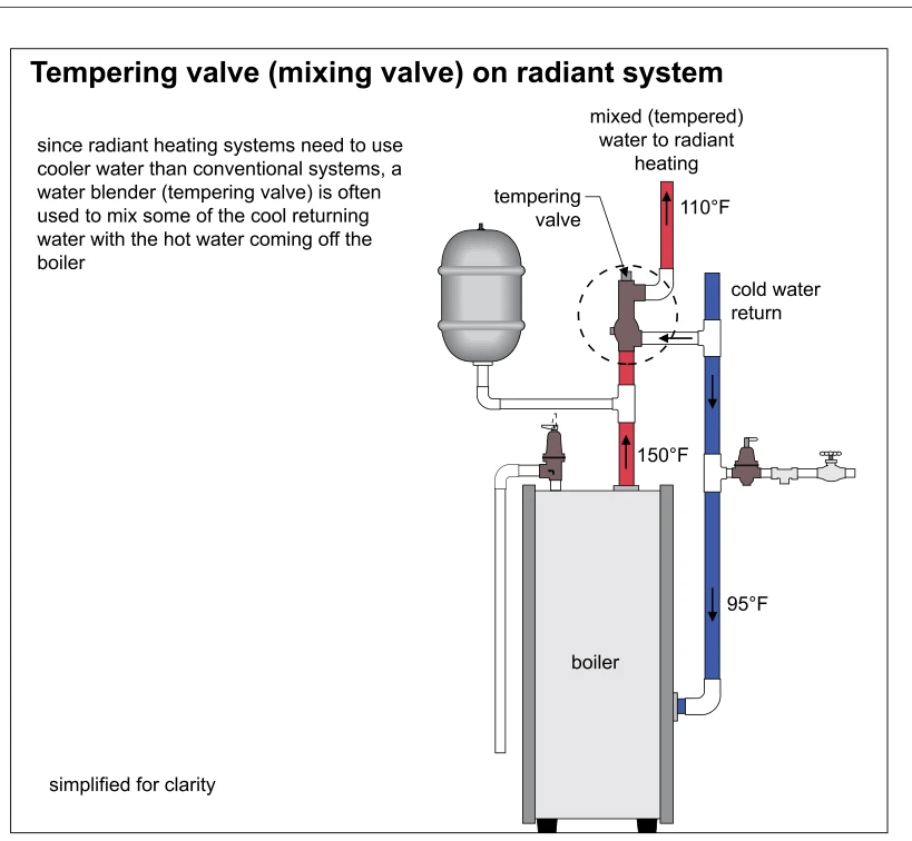
0899Tempering valve (mixing valve) on radiant system
· p. 156
This simplified hydronic radiant-heating schematic shows a tempering valve blending hot boiler supply water with cooler return water. The boiler supply is labeled 150°F, the return 95°F, and the mixed supply to the radia
 0906
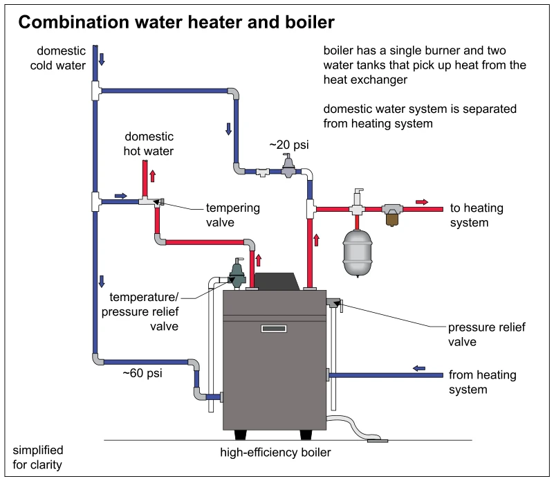
0906Combination water heater and boiler
· p. 159
The schematic depicts a high-efficiency combination boiler and domestic water heater with a single burner and two separate water tanks heated by a heat exchanger. Blue piping supplies domestic cold water at approximately
 0905
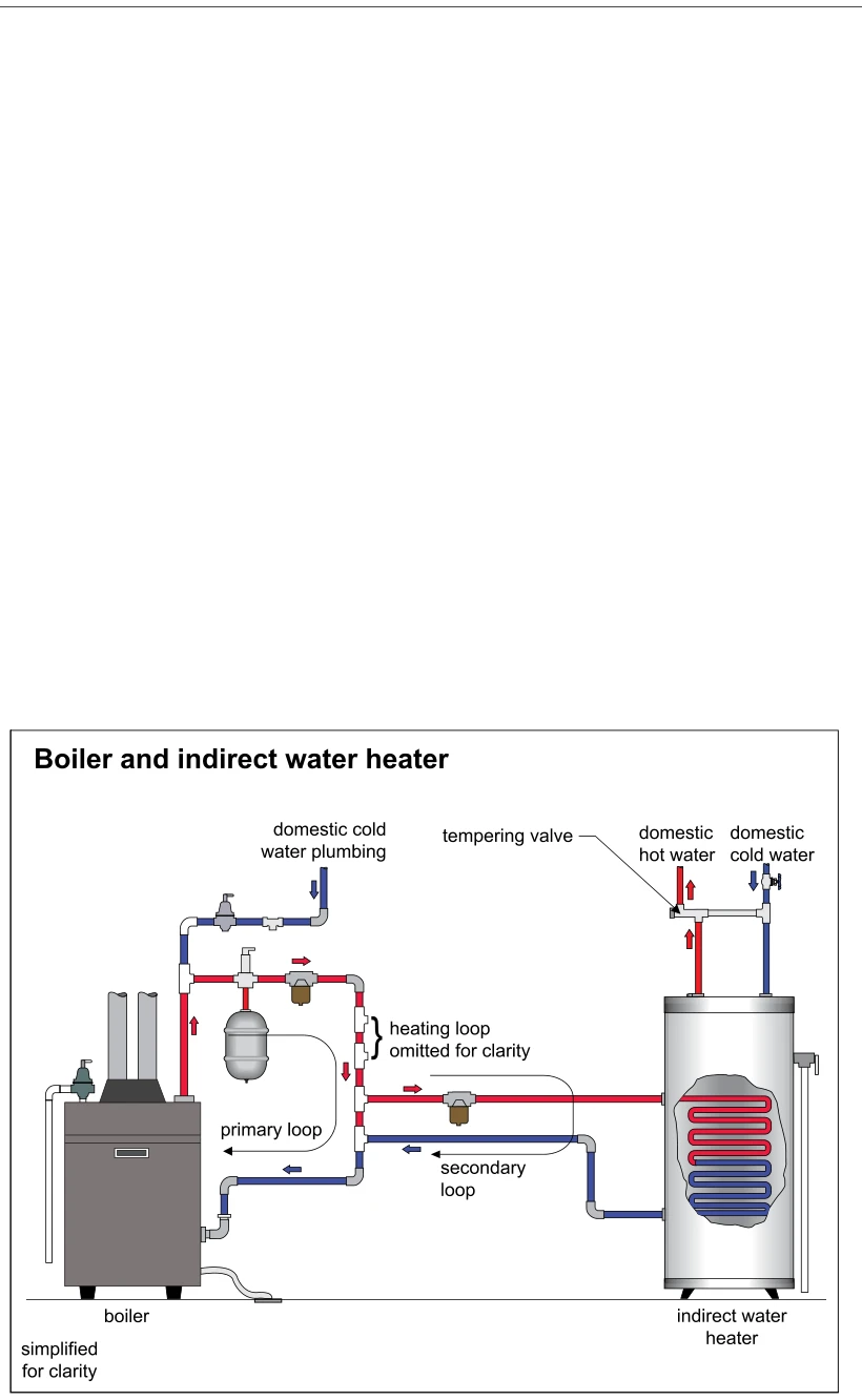
0905Boiler and indirect water heater
· p. 159
The schematic shows a boiler connected to an indirect domestic water heater through primary and secondary hydronic loops. Red and blue piping and directional arrows distinguish heated supply water from cooler return wate
 0903.5
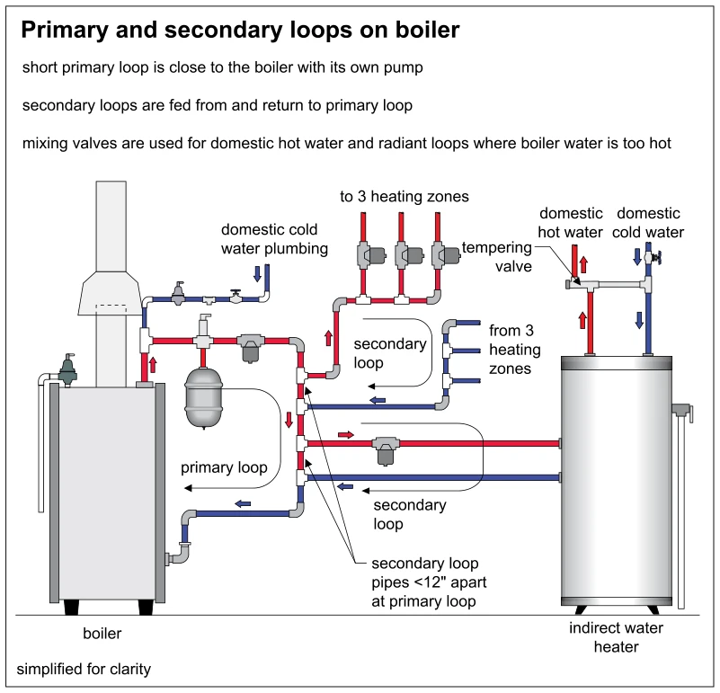
Primary and secondary loops on boiler
· p. 158
This schematic shows a boiler with a short, pumped primary loop supplying secondary circuits for three heating zones and an indirect water heater. Red supply pipes, blue return pipes, and arrows indicate water flow throu