
07Plumbing
223 illustrations · printed pages 257-300
Supply Plumbing ·Flow and Pressurep. 258
 1500
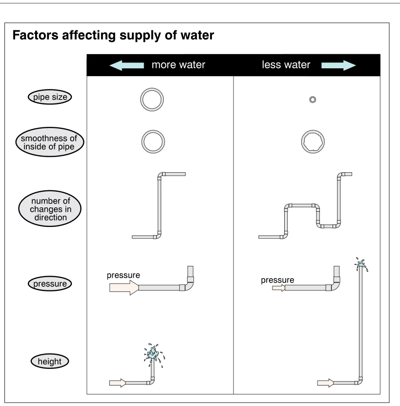
1500Factors affecting supply of water
· p. 258
The illustration compares five factors affecting water supply, with more water shown on the left and less water on the right. Pipe cross-sections contrast larger and smaller diameters and smooth versus irregular interior surfaces. Pipe runs contrast fewer changes in direction with a more circuitous route containing additional elbows. Arrows represent higher and lower supply pressure, while open-ended vertical pipes compare lower and higher discharge elevations. The diagram indicates that larger, smoother pipes, fewer bends, higher pressure, and lower discharge height favor greater water flow.
 1501
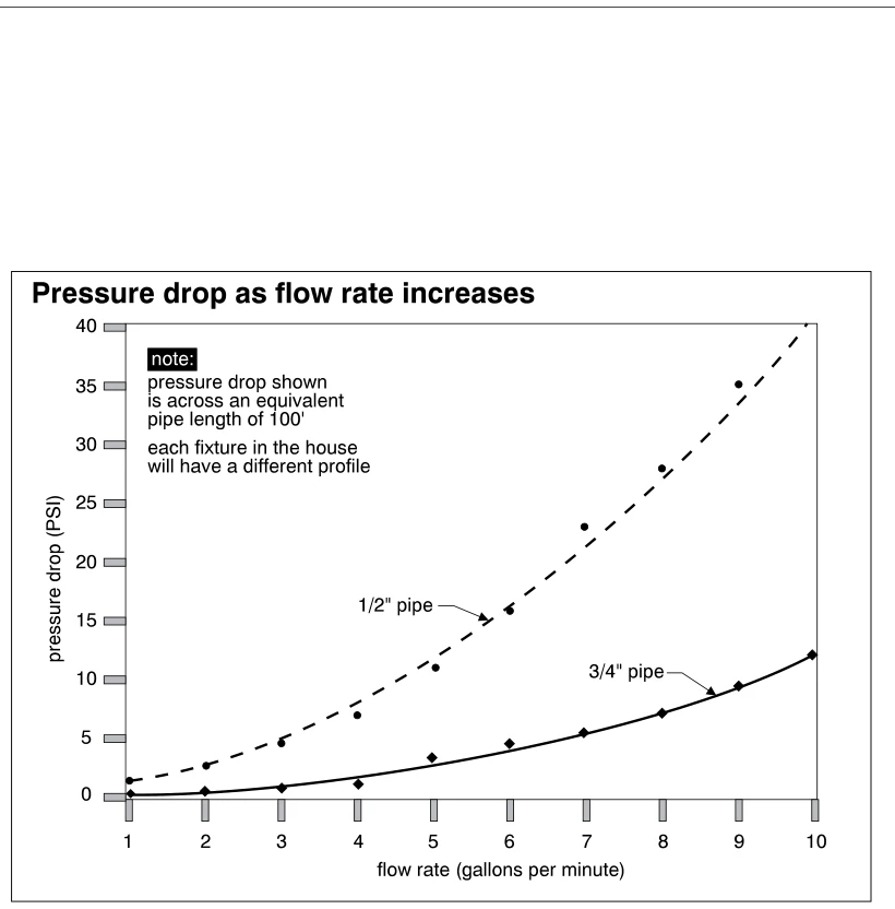
1501Pressure drop as flow rate increases
· p. 258
The illustration graphs water-supply pressure drop against flow rate for 1/2-inch and 3/4-inch pipes. A dashed curve with circular data points represents the 1/2-inch pipe, while a solid curve with diamond data points represents the 3/4-inch pipe. Both curves rise as flow increases, but pressure loss is substantially greater in the smaller pipe at the same flow rate. The graph covers flows from 1 to 10 gallons per minute and pressure drops up to 40 PSI. A note specifies an equivalent pipe length of 100 feet and states that each fixture in the house will have a different profile.
 1502
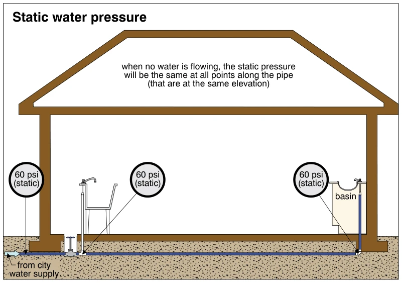
1502Static water pressure
· p. 258
A schematic house section shows a water supply pipe entering from the city water supply and running horizontally beneath the floor to two plumbing fixtures. Vertical branches connect the horizontal supply pipe to the fixture faucets, including a labeled basin on the right. Three callouts indicate 60 psi static pressure at points along the supply pipe at the same elevation. The illustration explains that, when no water is flowing, static pressure is the same at all points along the pipe that are at the same elevation.
 1503
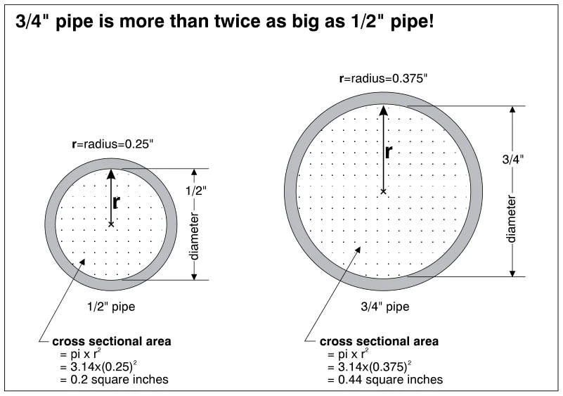
15033/4" pipe is more than twice as big as 1/2" pipe!
· p. 258
The illustration compares circular cross sections of 1/2-inch and 3/4-inch water supply pipes. Gray rings represent the pipe walls, with arrows identifying the radius and diameter of each opening. The 1/2-inch pipe is labeled with a 0.25-inch radius and a calculated cross-sectional area of 0.2 square inches. The 3/4-inch pipe is labeled with a 0.375-inch radius and an area of 0.44 square inches. The comparison demonstrates that the larger pipe has more than twice the cross-sectional area of the smaller pipe.
 1504
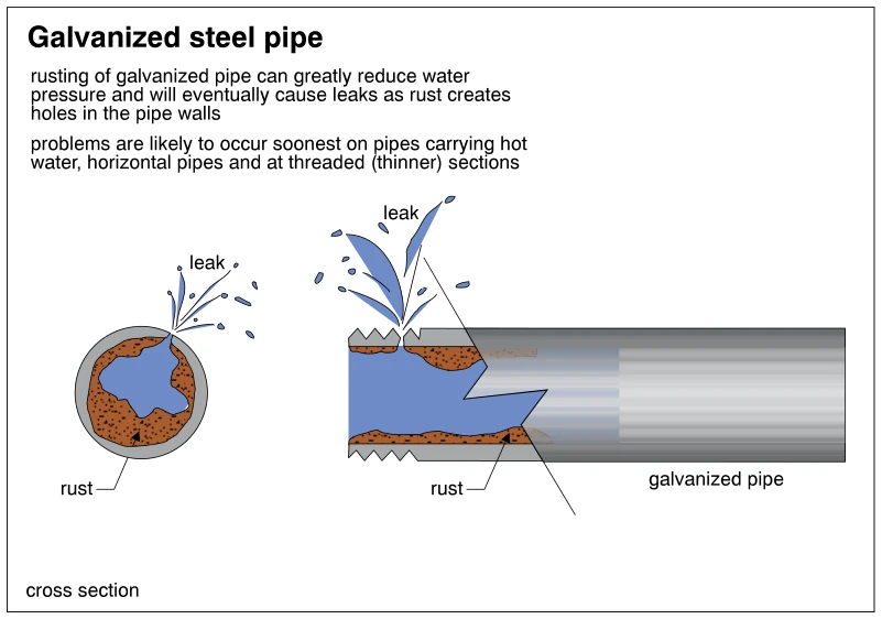
1504Galvanized steel pipe
· p. 258
The illustration shows a circular cross section and a longitudinal cutaway of galvanized steel water-supply pipe. Orange-brown rust deposits line the interior and narrow the water passage. Both views show water spraying through holes in the pipe wall caused by corrosion. The longitudinal view also shows a threaded pipe end. The annotations identify reduced water pressure and eventual leakage as consequences of rusting, with problems likely to occur first in hot-water pipes, horizontal runs, and thinner threaded sections.
 1505
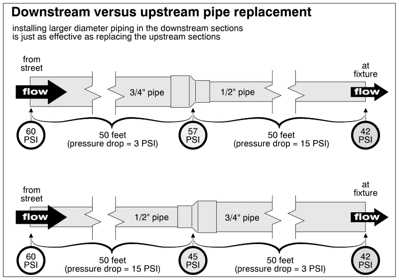
1505Downstream versus upstream pipe replacement
· p. 258
Two schematic water-supply runs compare the effects of locating larger-diameter piping upstream versus downstream between the street and a fixture. The upper run has 50 feet of 3/4-inch pipe followed by 50 feet of 1/2-inch pipe, with indicated pressures decreasing from 60 PSI to 57 PSI and then 42 PSI. The lower run reverses the pipe sizes, with pressures decreasing from 60 PSI to 45 PSI and then 42 PSI. Each 3/4-inch section has a labeled pressure drop of 3 PSI, while each 1/2-inch section has a drop of 15 PSI. The illustration explains that installing larger piping downstream is just as effective as replacing upstream sections in the configurations shown.
 1506
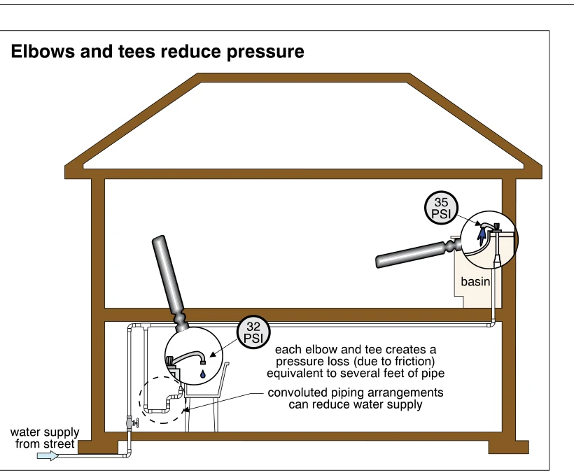
1506Elbows and tees reduce pressure
· p. 259
A schematic house section shows water supply piping entering from the street and serving fixtures on two levels. Magnified faucet details indicate 35 PSI at the upper basin and 32 PSI at the lower fixture. The lower fixture supply includes a convoluted piping route with multiple changes in direction, highlighted by a dashed circle. Annotations explain that elbows and tees create frictional pressure losses equivalent to several feet of pipe and that convoluted piping arrangements can reduce water supply.
 1507
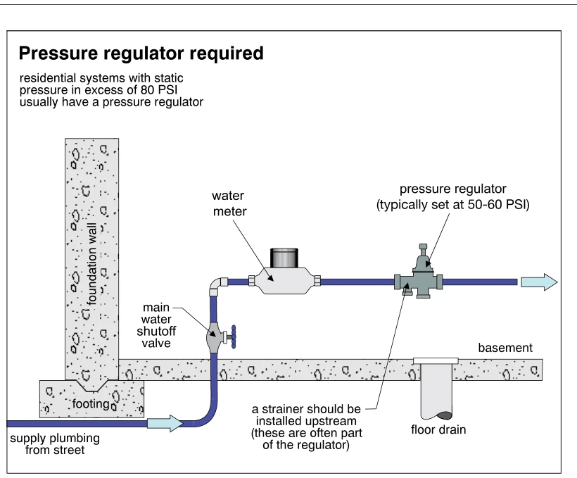
1507Pressure regulator required
· p. 259
The illustration shows a residential water service entering beneath a foundation footing and rising through the basement floor to a main water shutoff valve. The piping then turns horizontally through a water meter and a downstream pressure regulator, with arrows indicating flow from the street toward the house distribution piping. An annotation states that residential systems with static pressure exceeding 80 PSI usually have a pressure regulator, typically set at 50–60 PSI. A strainer is called for upstream of the regulator and is noted as often being part of the regulator. A nearby floor drain is shown in the basement slab.
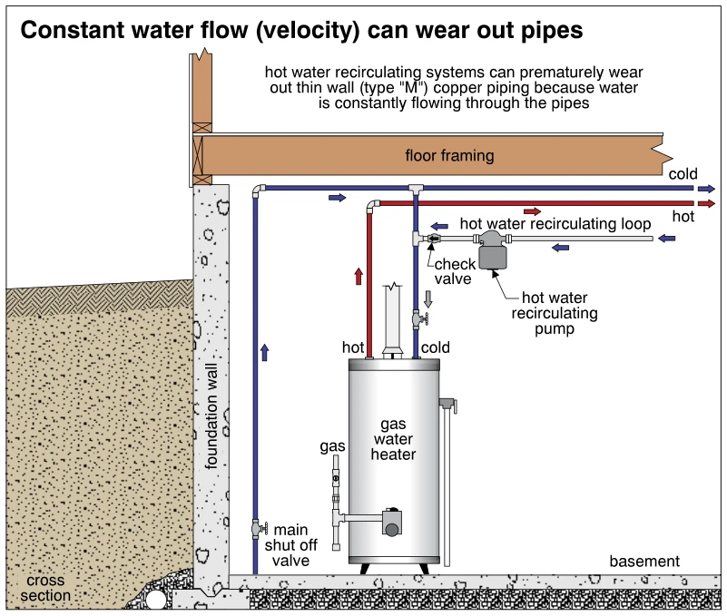 1508
1508Constant water flow (velocity) can wear out pipes
· p. 259
A basement cross section shows a gas water heater connected to cold-water supply piping, hot-water distribution piping, and a hot-water recirculating loop. Arrows indicate flow through the supply, heater, and pumped return loop, which connects to the heater's cold-water inlet piping through a check valve. The incoming water service has a main shutoff valve near the basement floor. An annotation warns that constant circulation can prematurely wear out thin-wall Type M copper piping; no actual pipe perforation or leak is drawn.
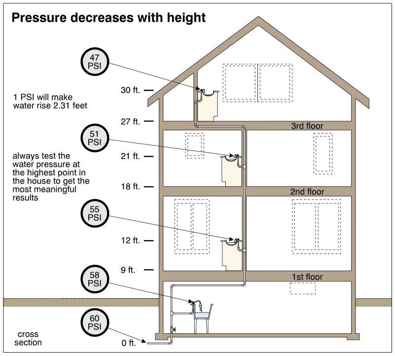 1509
1509Pressure decreases with height
· p. 259
A house cross section shows a water supply pipe entering at the basement and rising to fixtures on three floors. Pressure callouts decrease from 60 PSI at the supply entry to 58 PSI at the basement fixture, 55 PSI at the first-floor fixture, 51 PSI at the second-floor fixture, and 47 PSI at the third-floor fixture. Elevation marks indicate heights from 0 to 30 feet. An annotation states that 1 PSI will make water rise 2.31 feet, and another recommends testing water pressure at the highest point in the house for the most meaningful results.
Supply Plumbing ·Private Water Sourcesp. 260
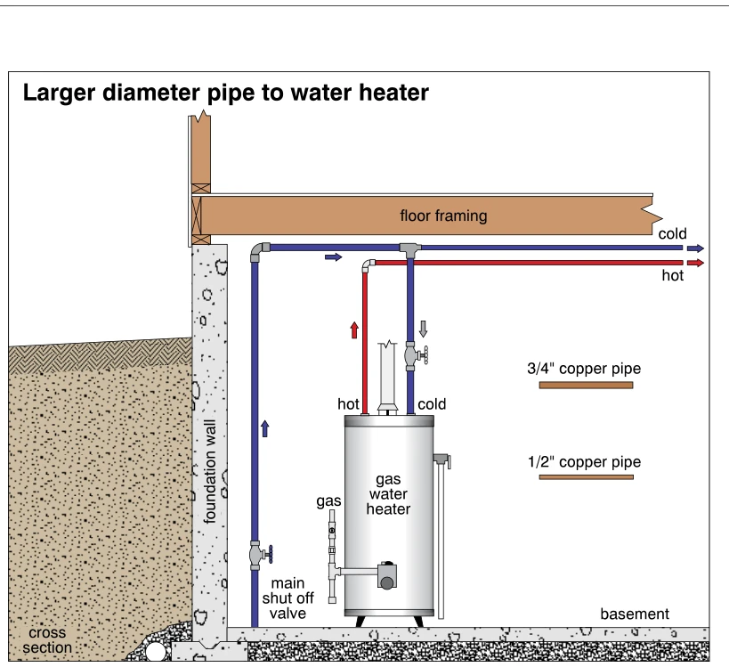 1510
1510Larger diameter pipe to water heater
· p. 260
A basement cross section shows a gas-fired storage water heater connected to hot- and cold-water supply piping beneath the floor framing. The incoming cold-water line rises beside the foundation wall through a main shutoff valve and branches down to the water heater through another valve. The cold-water feed to the heater is depicted with larger-diameter piping than the hot-water outlet, with reference samples labeled 3/4-inch and 1/2-inch copper pipe. Arrows indicate cold water flowing toward the distribution piping and into the heater, and hot water flowing upward from the heater to the hot-water distribution line. A gas supply connection, a short top vent connection, and a side-mounted relief valve with a discharge pipe are also shown.
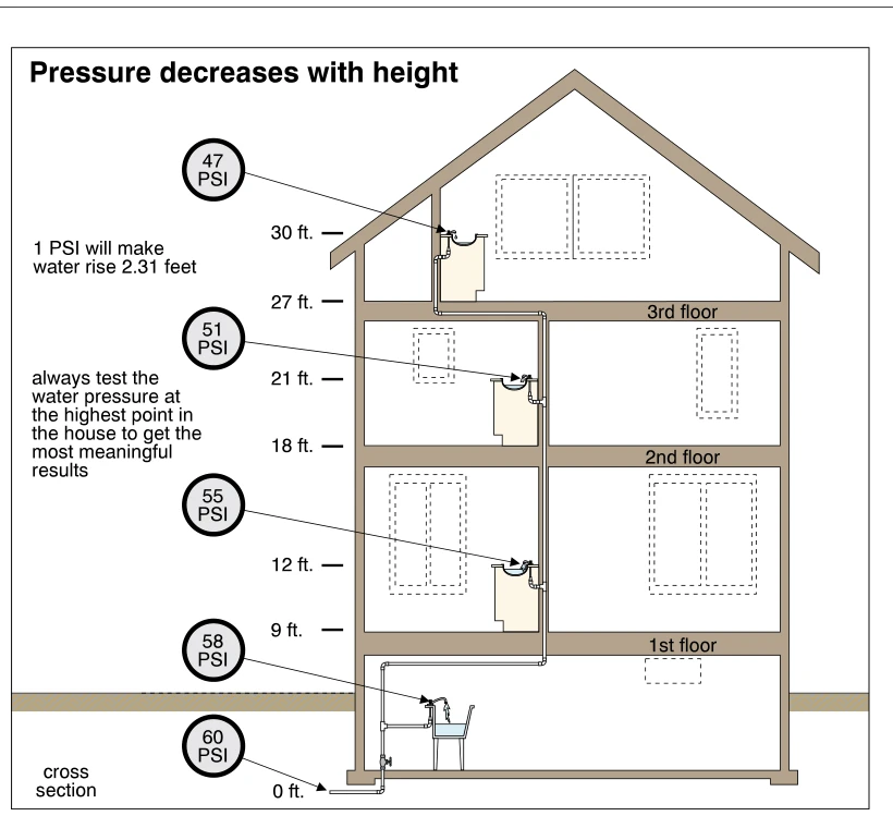 1511
1511Pressure decreases with height
· p. 260
A house cross section shows a water supply pipe entering at the basement level and rising to serve fixtures on three floors above. Pressure callouts decrease from 60 PSI at the 0-foot entry elevation to 58 PSI at the basement fixture, 55 PSI at 12 feet, 51 PSI at 21 feet, and 47 PSI at 30 feet. Elevation marks and floor labels relate the fixture heights to the supply entry. An annotation states that 1 PSI will raise water 2.31 feet, and another recommends testing water pressure at the highest point in the house for the most meaningful results.
 1512
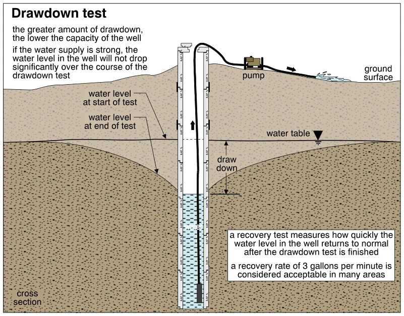
1512Drawdown test
· p. 260
The cross section depicts a well undergoing a drawdown test, with a surface pump lifting water through a pipe and discharging it onto the ground. A foot valve is shown at the submerged lower end of the pipe inside the well casing. The initial water table and the lowered water level during pumping define the drawdown, with a cone-shaped depression in the surrounding groundwater surface. Annotations explain that greater drawdown indicates lower well capacity and that a strong supply produces relatively little water-level drop. A boxed note describes recovery testing after pumping stops and states that a recovery rate of 3 gallons per minute is considered acceptable in many areas.
 1513
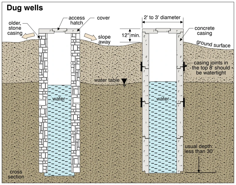
1513Dug wells
· p. 260
The illustration shows cross sections of two dug wells, one with an older stone casing and the other with a segmented concrete casing. Both have covers with access hatches and extend below the water table, with water occupying their lower portions. The ground is shown sloping away from the well openings, and a minimum 12-inch clearance is indicated between grade and the top of the concrete casing. The concrete well is labeled as 2 to 3 feet in diameter, with a usual depth of less than 30 feet. Its casing joints in the upper 8 feet are specified to be watertight.
 1514
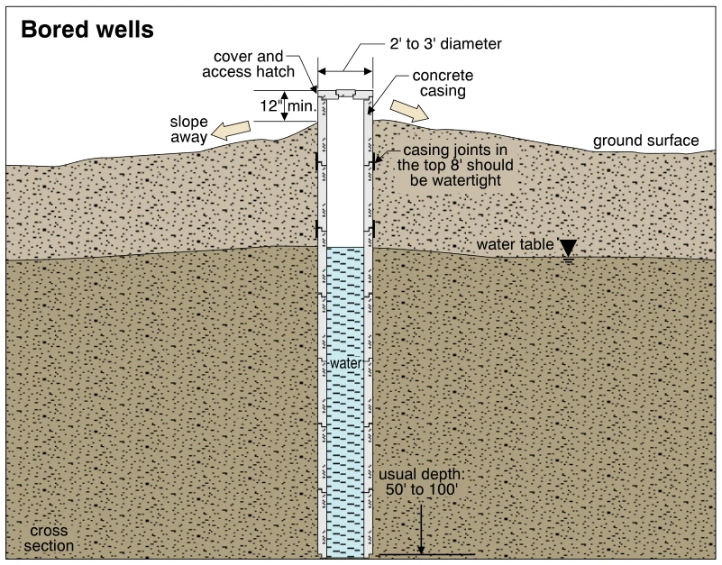
1514Bored wells
· p. 260
The illustration shows a cross section of a bored well with a segmented concrete casing, a cover, and an access hatch. The well is labeled as 2 to 3 feet in diameter with a usual depth of 50 to 100 feet, and water occupies the casing below the water table. The casing projects at least 12 inches above the surrounding ground, which slopes away from the well. An annotation specifies that casing joints in the top 8 feet should be watertight.
 1515
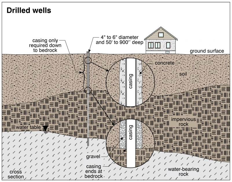
1515Drilled wells
· p. 260
The cross section depicts a drilled well near a house, extending through soil and impervious rock into water-bearing rock below the water table. The well is labeled as 4 to 6 inches in diameter and 50 to 900-plus feet deep. Two enlarged details show concrete around the casing near the surface and gravel around the casing where it reaches bedrock. The casing ends at bedrock, while the drilled bore continues down into the water-bearing formation.
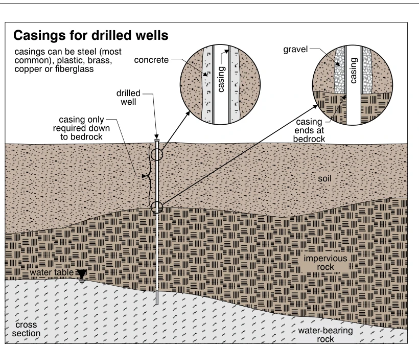 1516
1516Casings for drilled wells
· p. 261
The cross section shows a drilled well extending through soil and impervious rock into water-bearing rock below the indicated water table. The casing lines the upper portion of the well, with annotations stating that it is only required down to bedrock and ends at bedrock. One enlarged detail shows concrete surrounding the casing in the soil. A second enlarged detail shows gravel outside the casing above the bedrock interface. An annotation lists steel, plastic, brass, copper, and fiberglass as possible casing materials.
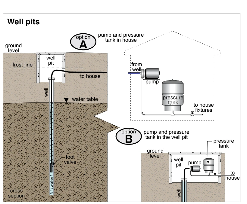 1517
1517Well pits
· p. 261
The illustration compares two private well arrangements using a covered well pit below ground level. A cross section shows the well extending below the water table, with a foot valve on the submerged intake pipe and the supply line to the house below the indicated frost line. Option A places the pump and pressure tank inside the house, connected to the well and the house fixtures. Option B places both the pump and pressure tank within the well pit, with an outlet pipe running to the house. No specific defect is marked.
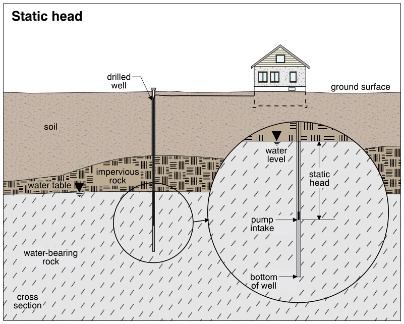 1518
1518Static head
· p. 261
A cross section shows a drilled well beside a house extending through soil and impervious rock into water-bearing rock below the water table. A circular enlargement shows the water level, pump intake, and bottom of the well. A vertical double-headed arrow identifies static head as the vertical distance from the water level to the pump intake. The well continues below the intake, distinguishing static head from the full water depth in the well. No defect or improper installation is depicted.
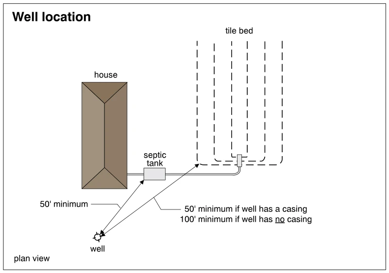 1519
1519Well location
· p. 261
The illustration is a plan view showing a house, a septic tank, a tile bed, and a separate water well. A pipe connects the house to the septic tank and continues to the tile bed distribution piping. Dimension arrows indicate a minimum separation of 50 feet between the well and the septic tank. The indicated minimum separation between the well and the tile bed is 50 feet if the well has a casing, or 100 feet if it has no casing.
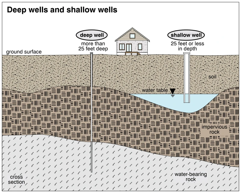 1520
1520Deep wells and shallow wells
· p. 261
A ground cross section beneath a house compares deep and shallow private water wells. The deep well, labeled more than 25 feet deep, extends through soil and impervious rock into underlying water-bearing rock. The shallow well, labeled 25 feet or less in depth, terminates in a near-surface water zone above the impervious rock. A water-table marker identifies the upper surface of the shallow water zone. The illustration explains the relative depths and geological settings without depicting installation defects.
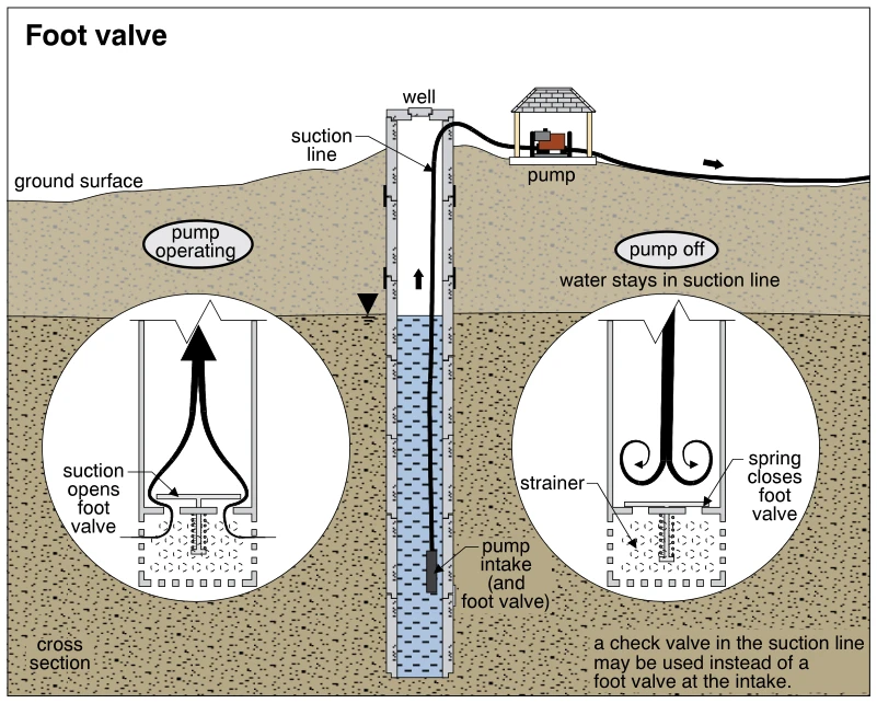 1521
1521Foot valve
· p. 261
A cross section shows a well with a submerged suction-line intake and foot valve connected to an aboveground pump. Two enlarged details illustrate the valve during pump operation and when the pump is off. During operation, suction opens the foot valve and water flows upward through the suction line. When the pump stops, a spring closes the valve, retaining water in the suction line. A strainer surrounds the intake, and an annotation notes that a check valve in the suction line may be used instead of a foot valve at the intake.
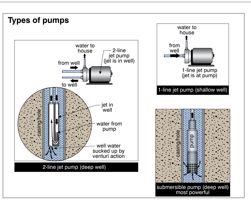 1522
1522Types of pumps
· p. 262
The illustration shows three pump arrangements for private well water supplies. The two-line deep-well jet pump sits above the well and circulates water down to a jet in the well, where venturi action draws in well water for return to the pump and delivery to the house. The one-line shallow-well jet pump has its jet at the aboveground pump, with an inlet from the well and an outlet to the house. The deep-well submersible pump is positioned within the water-filled well casing and pushes water upward through a discharge pipe; it is labeled as the most powerful type. Arrows indicate water flow through each arrangement.
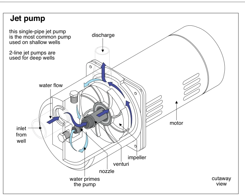 1523
1523Jet pump
· p. 262
A cutaway view shows a single-pipe jet pump with an electric motor connected to the pump assembly. The exposed housing reveals the impeller, nozzle, and venturi, with an inlet from the well at the front and a discharge connection at the top. Colored arrows trace water flow through the pump and the internal circulation identified as priming the pump. Notes identify this single-pipe design as the most common pump used on shallow wells and state that two-line jet pumps are used for deep wells.
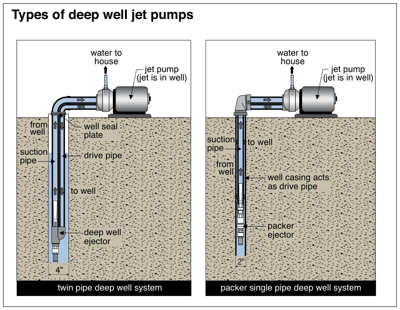 1523.5
Types of deep well jet pumps
· p. 262
The illustration compares a twin-pipe deep well jet pump system with a packer single-pipe deep well jet pump system. Both have an aboveground pump supplying water to the house and an ejector located down in the well. The twin-pipe arrangement shows separate suction and drive pipes passing through a well seal plate to a deep well ejector, with a 4-inch dimension across the well. The packer arrangement shows a suction pipe inside a well casing that acts as the drive pipe, a packer ejector below, and a 2-inch dimension across the casing. Arrows indicate water traveling down the drive passage toward the ejector and returning upward through the suction pipe.
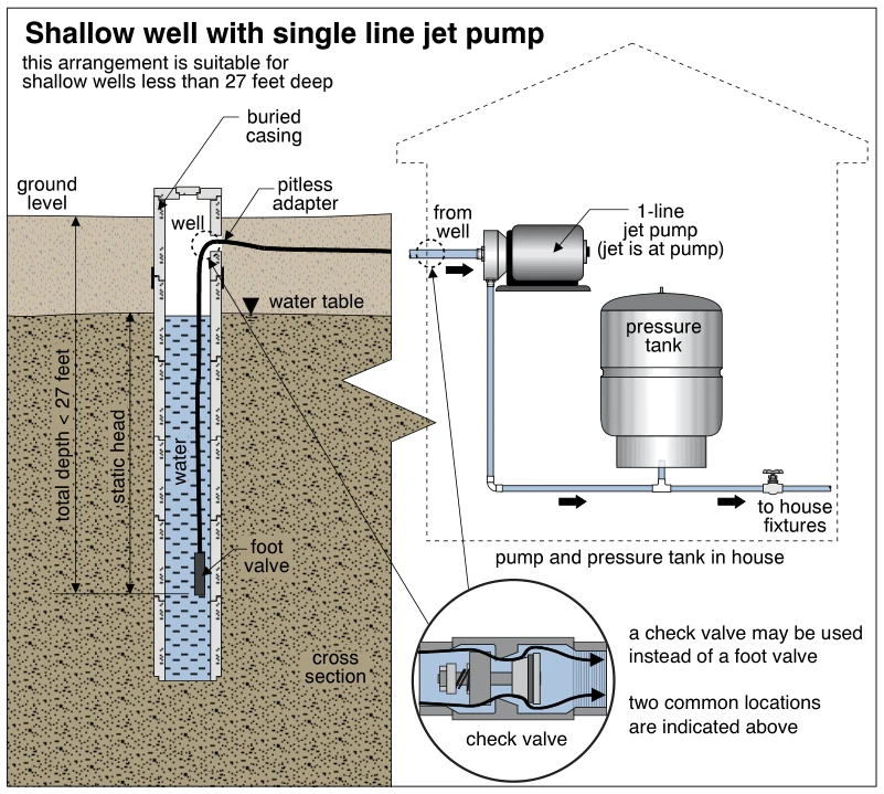 1524
1524Shallow well with single line jet pump
· p. 262
The illustration shows a shallow well connected by a single suction line to an indoor jet pump and pressure tank. The suction pipe extends down the well casing to a foot valve below the water table and exits through a pitless adapter below ground level. Dimension arrows identify static head and a total depth of less than 27 feet, the stated limit for this arrangement. Flow arrows trace water from the well through the pump and into the distribution line serving house fixtures, with the pressure tank connected to that line. An enlarged check-valve cross section explains that a check valve can replace the foot valve, with two possible locations indicated along the suction piping.
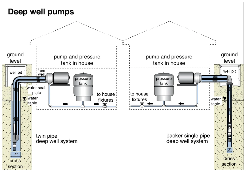 1525
1525Deep well pumps
· p. 262
The illustration compares a twin-pipe deep-well system with a packer single-pipe deep-well system. Both show a pump and pressure tank inside a house, connected through a well pit to piping extending below the water table. The twin-pipe arrangement has two pipes descending into a well marked 4 inches, while the packer arrangement uses a single-pipe configuration in a well marked 2 inches. Arrows indicate flow through the well piping and along the supply piping to house fixtures. A water seal plate is identified at the top of the twin-pipe well; no defects are indicated.
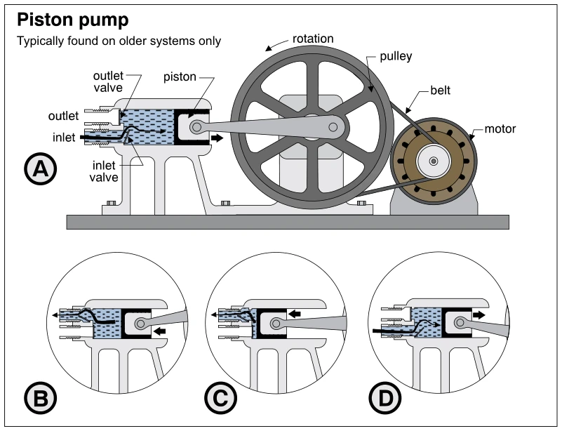 1526
1526Piston pump
· p. 262
The illustration shows a belt-driven piston pump used in older private well-water systems. A motor drives a large pulley and crank linkage, converting rotary motion into reciprocating piston movement inside the pump cylinder. The cylinder has separate inlet and outlet passages with valves controlling water flow. The main view and three circular details show successive piston positions: inward travel discharges water through the outlet valve, while outward travel draws water through the inlet valve. Arrows indicate pulley rotation, piston travel, and water-flow direction.
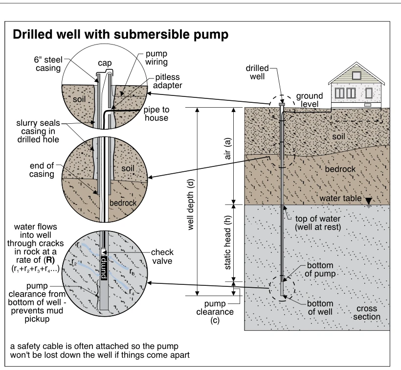 1527
1527Drilled well with submersible pump
· p. 263
A cross section shows a drilled well extending through soil into bedrock, with a submersible pump below the resting water level supplying a house. Enlarged details show the capped steel casing, slurry seal, pump wiring, and pitless adapter connecting the vertical pipe to the buried pipe to the house. The casing extends into bedrock, and water enters the lower well through cracks in the rock. A check valve is located above the pump, and clearance below the pump prevents mud pickup from the well bottom. Dimension arrows identify well depth, air above the water, static head, and pump clearance; a note describes a safety cable used to prevent loss of the pump if connections come apart.
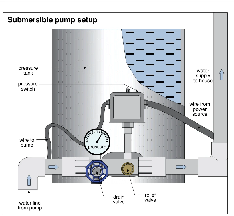 1527.5
Submersible pump setup
· p. 263
The illustration shows the pressure-tank and control assembly for a submersible well pump system. Water enters from the pump through the lower-left pipe, passes the tank connection and valve assembly, and flows toward the house through the right-hand riser, as indicated by arrows. A pressure gauge, drain valve, and relief valve are mounted at the tank piping. A pressure switch above the piping has electrical connections labeled to the pump and from the power source. A cutaway of the pressure tank shows water inside; no defects are indicated.
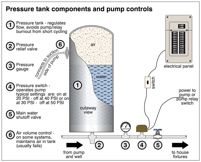 1528
1528Pressure tank components and pump controls
· p. 263
The illustration shows a well-water pressure tank in cutaway, with air above water and a connection to the distribution piping below. Numbered callouts identify the tank, pressure relief valve, pressure gauge, pressure switch, main water shutoff valve, and air volume control. Flow arrows indicate water arriving from the pump and well and continuing to house fixtures. An electrical panel supplies a switch and the pressure-switch control circuit, with power continuing to the pump or pump relay switch. An air volume control connects to the suction side of the pump; the annotations explain short-cycling protection and typical pump cut-in and cut-out pressure settings.
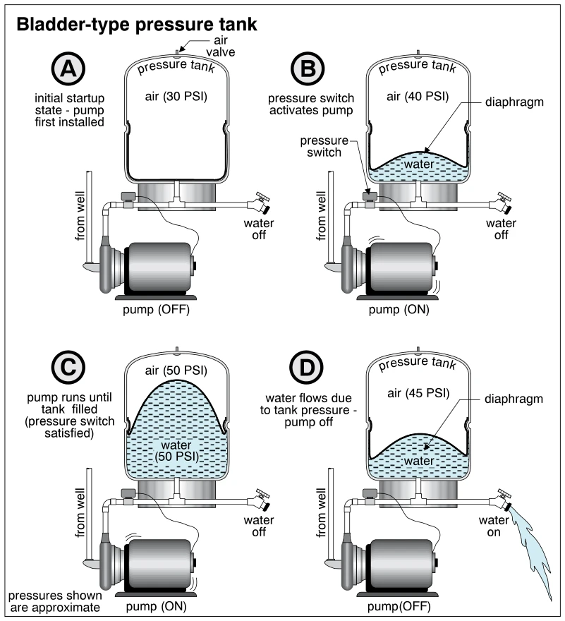 1529
1529Bladder-type pressure tank
· p. 263
Four sequential diagrams show the operation of a bladder-type pressure tank connected to a well pump, pressure switch, and outlet faucet. Panel A shows the initial installation state with 30 PSI air pressure, the pump off, and the water outlet closed. Panel B shows the pressure switch activating the pump, with water entering beneath the diaphragm and air at 40 PSI. Panel C shows the pump running until the tank is filled and the pressure switch is satisfied, with both air and water labeled 50 PSI. Panel D shows water discharging from the open faucet under tank pressure while the pump is off, with air pressure reduced to 45 PSI. A note states that the pressures shown are approximate.
Supply Plumbing ·Public Water Servicep. 264
 1529.5
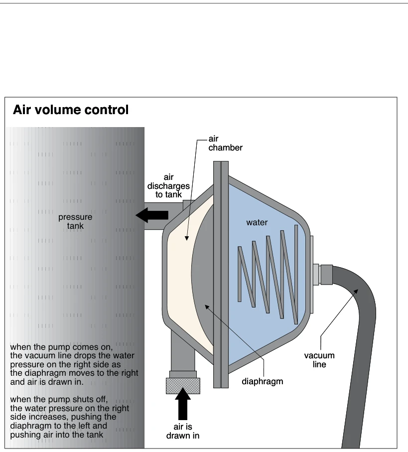
Air volume control
· p. 264
The illustration shows a sectional view of an air volume control connected to a pressure tank. A flexible diaphragm separates the air chamber on the left from a water-filled chamber containing a spring on the right, which connects to a vacuum line. Arrows show air entering through the bottom inlet and discharging through a side connection into the pressure tank. The annotations explain that pump operation reduces water pressure and moves the diaphragm right to draw in air; when the pump stops, increased water pressure moves the diaphragm left and pushes air into the tank.
 1530
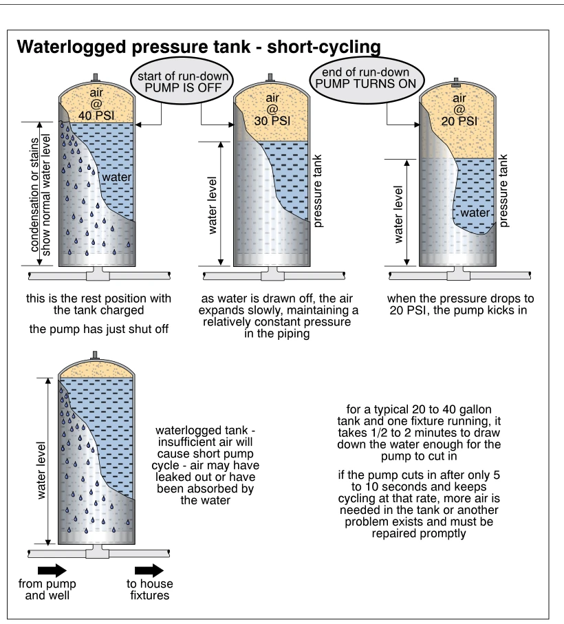
1530Waterlogged pressure tank - short-cycling
· p. 264
Three cutaway pressure-tank views show normal drawdown from 40 PSI with the pump off, through 30 PSI, to the 20 PSI pump cut-in point. As water leaves the tank, the air cushion expands and the water level falls. Condensation or stains on the tank exterior indicate the normal water level. A fourth view contrasts a waterlogged tank with a high water level and insufficient air, connected to piping from the pump and well and onward to house fixtures. The annotations explain that loss or absorption of air can cause rapid pump short-cycling and contrast normal drawdown time with repeated 5- to 10-second cycles.
 1531
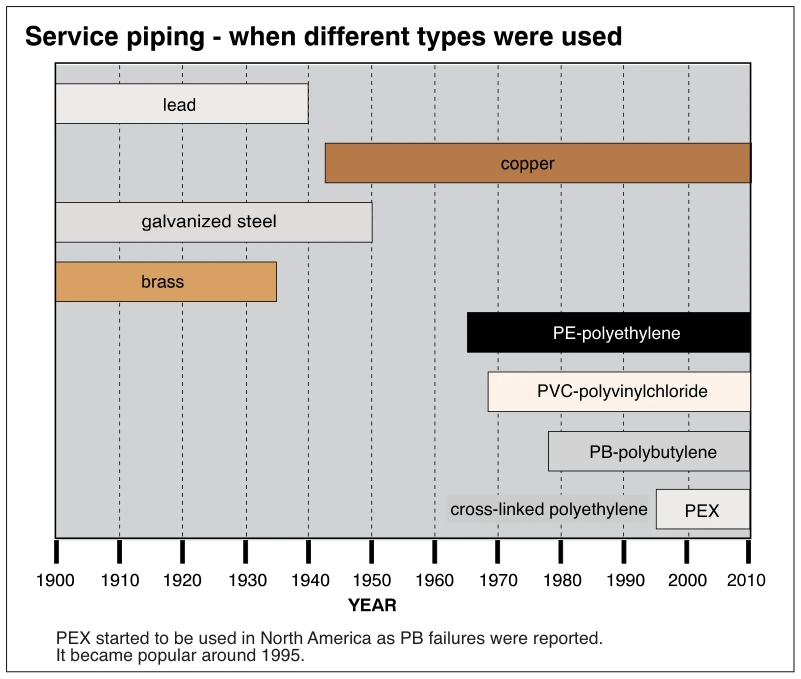
1531Service piping - when different types were used
· p. 264
This timeline charts the use of water service piping materials from 1900 through 2010. Bars show lead through approximately 1940, brass through the mid-1930s, and galvanized steel through 1950, with copper beginning in the early 1940s and continuing to the chart's endpoint. Plastic piping bars begin later: polyethylene in the mid-1960s, PVC near 1970, polybutylene in the late 1970s, and PEX around 1995. An annotation states that PEX began to be used in North America as polybutylene failures were reported and became popular around 1995. The illustration presents historical material-use periods rather than a physical piping installation.
 1532
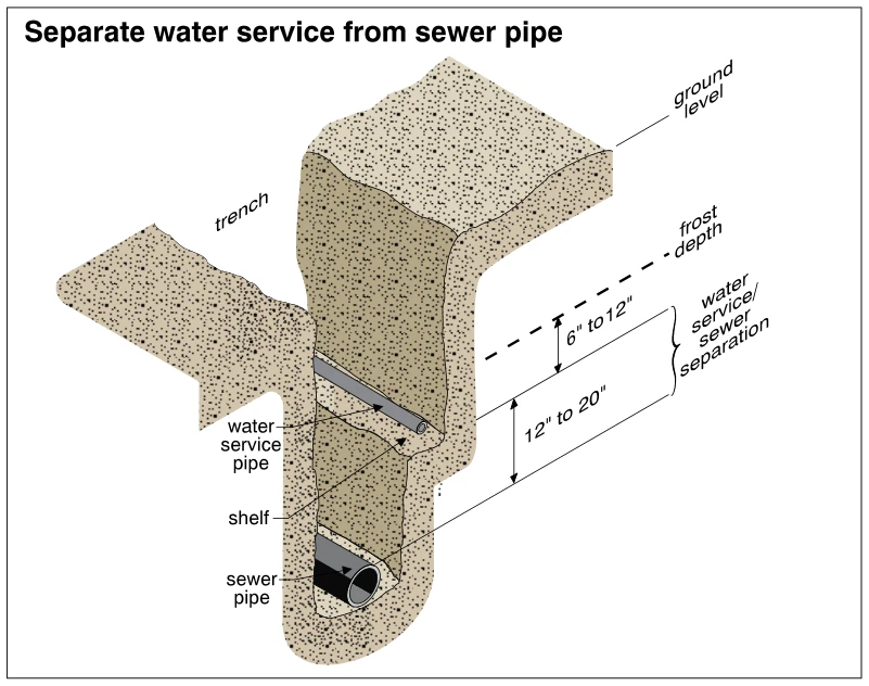
1532Separate water service from sewer pipe
· p. 264
The illustration shows a cutaway of a buried water service and sewer pipe within a stepped trench. The smaller water service pipe rests on a soil shelf above and laterally offset from the larger sewer pipe at the bottom of the trench. A dashed line marks frost depth, with the water service shown 6 to 12 inches below that line. A separate dimension indicates 12 to 20 inches of vertical separation between the water service and sewer pipe. The arrangement depicts separation of the potable water service from the sewer.
Supply Plumbing ·Distribution Piping In the Housep. 265
 1533
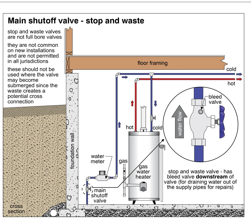
1533Main shutoff valve - stop and waste
· p. 265
A foundation cross section shows the incoming water supply passing through a main shutoff valve and water meter before rising to the cold-water distribution piping. A branch supplies a gas water heater, with separate hot-water piping leaving the heater. An enlarged detail shows a stop-and-waste shutoff valve with a bleed valve downstream of the shutoff, allowing supply piping to be drained for repairs. Notes state that these valves are not full bore, are uncommon in new installations, and are not permitted in all jurisdictions. The illustration warns against installing them where they may become submerged because the waste opening creates a potential cross connection.
 1534
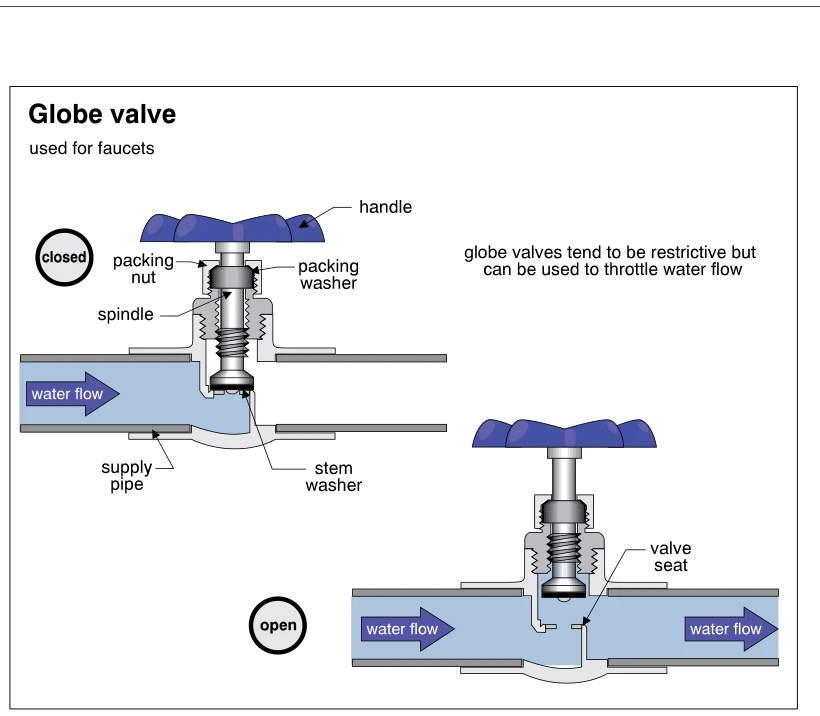
1534Globe valve
· p. 265
Two sectional drawings show a globe valve in closed and open positions within a water supply pipe. The handle operates a threaded spindle that raises or lowers a stem washer against the valve seat. In the closed position, the washer seals the opening; in the open position, it is lifted to allow water through the offset passage. A packing nut and packing washer surround the spindle near the handle. Arrows indicate left-to-right water flow, and an annotation explains that globe valves restrict flow but can be used for throttling.
 1535
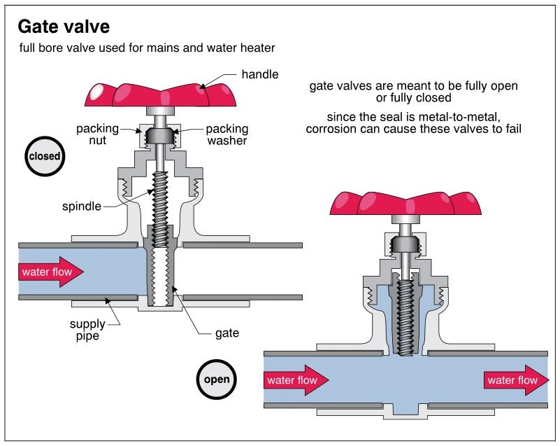
1535Gate valve
· p. 265
Two sectional views show a gate valve in its fully closed and fully open positions on a horizontal water supply pipe. In the closed view, the gate extends across the pipe bore and blocks water flow. In the open view, the gate is raised into the valve body, leaving the full bore clear for flow. The handle operates a threaded spindle, with a packing nut and packing washer surrounding the stem above the body. Annotations identify use on mains and water heaters, specify fully open or fully closed operation, and warn that corrosion of the metal-to-metal seal can cause valve failure.
 1536
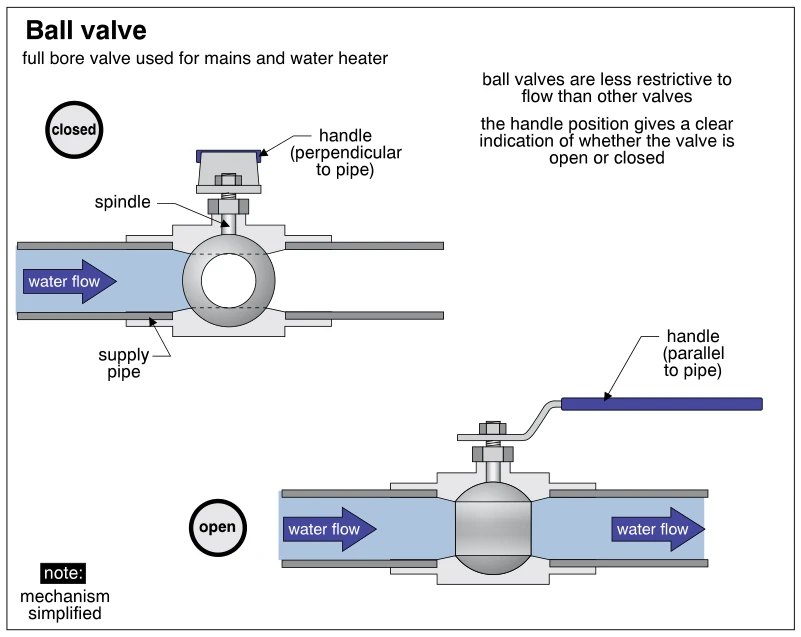
1536Ball valve
· p. 265
Two simplified sectional views depict a full-bore ball valve in closed and open positions in a water supply pipe. In the closed view, the handle is perpendicular to the pipe and the ball blocks flow through the valve. In the open view, the handle is parallel to the pipe and the ball's bore aligns with the pipe, allowing water to flow through. A spindle connects the handle to the ball. The annotations identify applications at water mains and water heaters and explain that ball valves restrict flow less than other valve types.
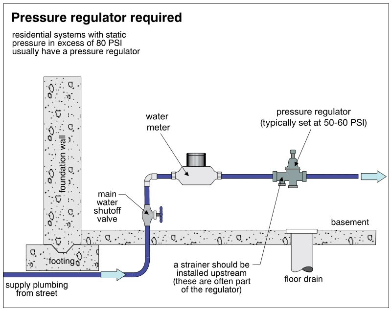 1537
1537Pressure regulator required
· p. 265
The illustration shows a street water supply entering beneath a foundation footing and rising into a basement. Flow arrows indicate water passing through a main water shutoff valve, a water meter, and then a pressure regulator before continuing into the house distribution piping. An annotation states that residential systems with static pressure above 80 PSI usually have a pressure regulator, typically set at 50–60 PSI. A callout specifies a strainer upstream of the regulator and notes that it is often integral to the regulator. The foundation wall, footing, basement slab, and a floor drain are shown for context.
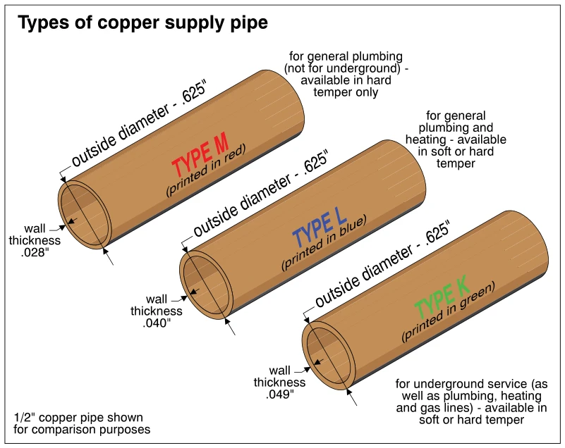 1538
1538Types of copper supply pipe
· p. 265
Three open-ended sections of nominal 1/2-inch copper supply pipe compare Types M, L, and K, each with a .625-inch outside diameter. Their wall thicknesses increase from .028 inch for Type M to .040 inch for Type L and .049 inch for Type K. Identification lettering is shown in red, blue, and green respectively. The annotations identify Type M for general plumbing, not underground, in hard temper only; Type L for general plumbing and heating in soft or hard temper; and Type K for underground service as well as plumbing, heating, and gas lines in soft or hard temper.
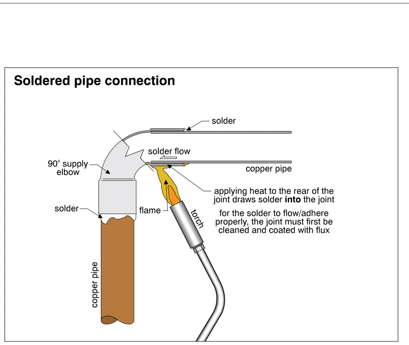 1539
1539Soldered pipe connection
· p. 266
The illustration shows a soldered 90-degree supply elbow connecting vertical and horizontal copper pipes. A cutaway at the horizontal connection reveals the overlapping pipe and fitting, with an arrow indicating solder flow into the joint. A torch flame heats the rear of this joint to draw solder into the connection. An annotation states that the joint must first be cleaned and coated with flux for solder to flow and adhere properly. Solder is also identified at the vertical pipe-to-elbow connection.
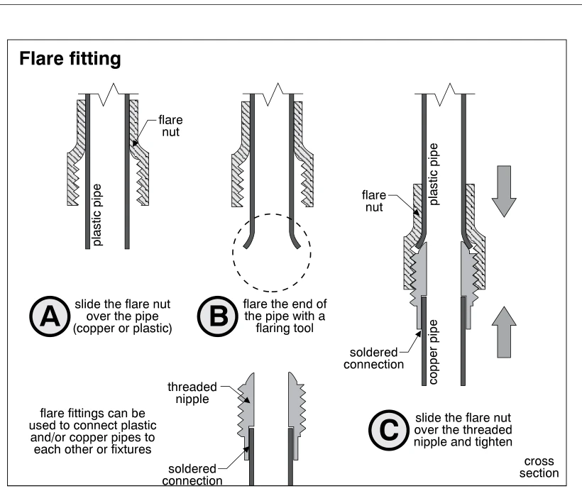 1540
1540Flare fitting
· p. 266
The illustration presents cross-sectional views of a flare fitting and its assembly sequence. Step A shows a flare nut slipped over a straight pipe, and step B shows the pipe end flared outward with a flaring tool. Step C shows the nut tightened onto a threaded nipple, capturing the flared plastic pipe end against the fitting. The nipple is shown joined to a copper pipe by a soldered connection, with a separate detail illustrating that joint. An annotation states that flare fittings can connect plastic and/or copper pipes to each other or to fixtures.
 1540.5
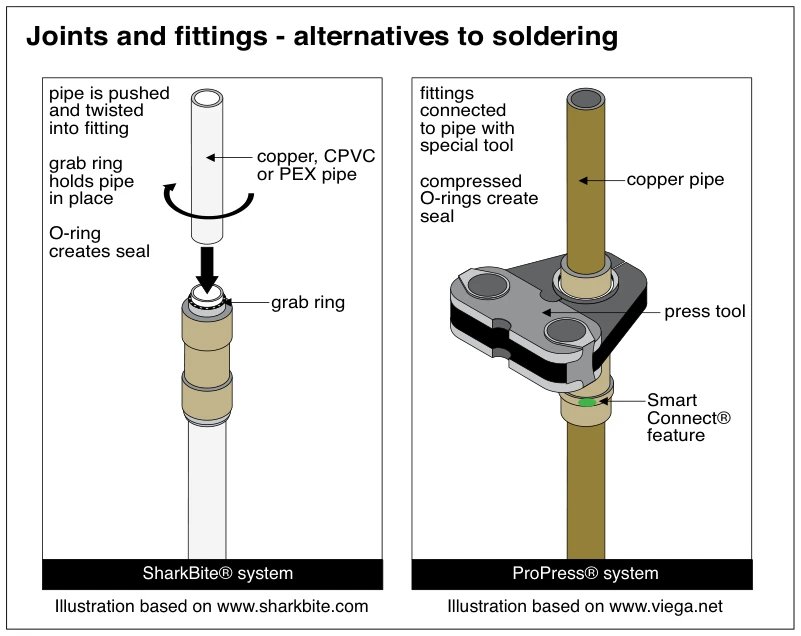
Joints and fittings - alternatives to soldering
· p. 266
The illustration shows two alternatives to soldered joints in water distribution piping. On the left, a SharkBite® push-fit coupling accepts copper, CPVC or PEX pipe, with arrows indicating that the pipe is pushed and twisted into the fitting. A grab ring holds the pipe in place, while an O-ring creates the seal. On the right, a ProPress® coupling joins copper pipe using a special press tool, with compressed O-rings providing the seal. The press tool is shown around the fitting, and a green Smart Connect® feature is identified below it.
 1541
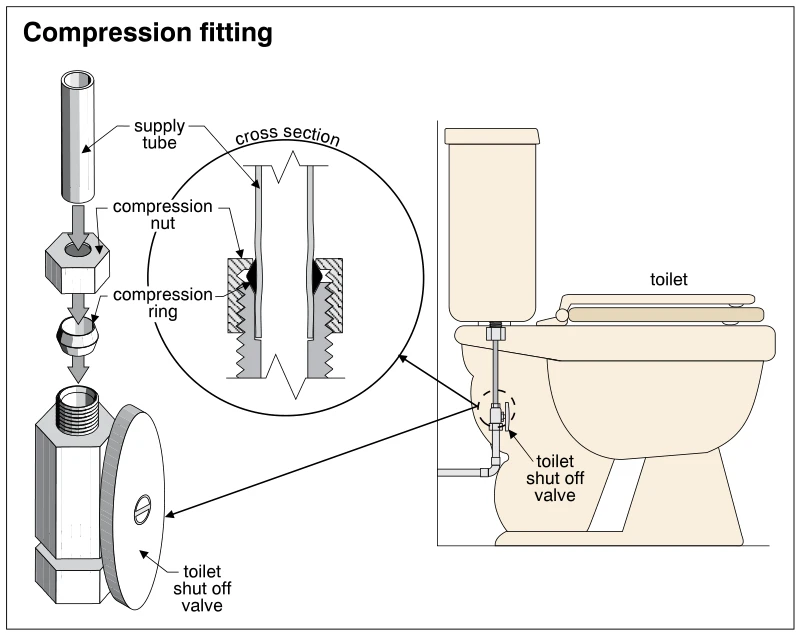
1541Compression fitting
· p. 266
The illustration shows a compression fitting connecting a supply tube to a toilet shutoff valve. An exploded view shows the supply tube passing through a compression nut and compression ring into the threaded valve connection. A circular cross section shows how the nut confines the compression ring around the tube at the valve body. A side view of a toilet locates the shutoff valve below the tank, between the wall supply piping and the vertical tank supply tube. No defects or improper installation practices are depicted.
 1542
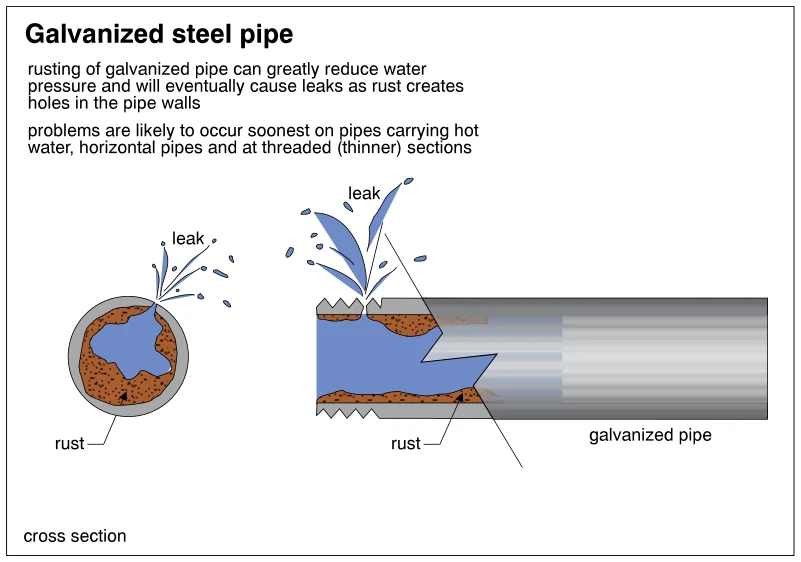
1542Galvanized steel pipe
· p. 266
The illustration shows a transverse cross section and a longitudinal cutaway of galvanized steel water-supply pipe. Rust deposits line the interior and substantially narrow the passage available for water flow. Both views show water spraying through holes in the pipe wall. The longitudinal view includes a threaded end, and the annotations identify hot-water pipes, horizontal pipes, and thinner threaded sections as locations likely to develop problems first.
 1543
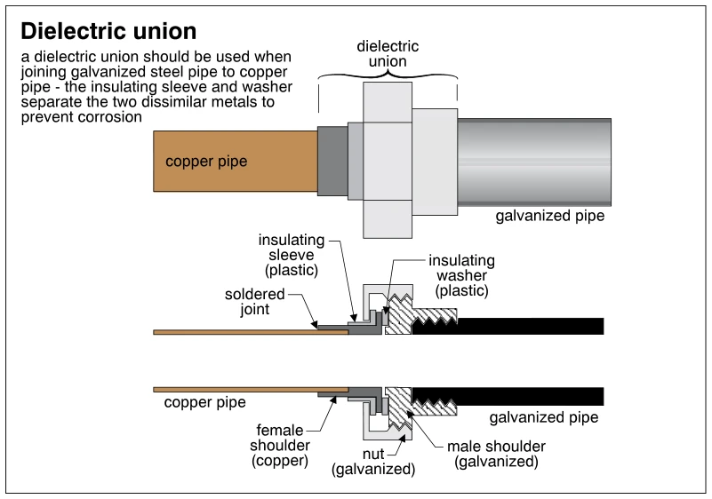
1543Dielectric union
· p. 266
The illustration shows an exterior view and a longitudinal section of a dielectric union connecting copper pipe to galvanized steel pipe. The section identifies a soldered connection at the copper female shoulder and a threaded connection at the galvanized male shoulder. A galvanized nut holds the union together, while a plastic insulating sleeve and washer separate the dissimilar metals. The annotation recommends this arrangement to prevent corrosion where copper and galvanized steel supply piping meet.
 1544
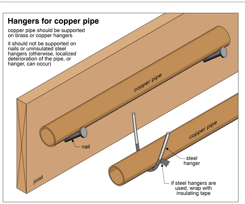
1544Hangers for copper pipe
· p. 267
The illustration shows copper distribution piping supported alongside a wood joist on nails, with a separate detail of a steel pipe hanger. The nail supports are identified as improper because contact with incompatible metals can cause localized deterioration of the pipe or hanger. The steel hanger detail shows insulating tape at the pipe-contact area and instructs that steel hangers must be insulated. The accompanying text specifies brass or copper hangers as the preferred supports for copper pipe.
 1545
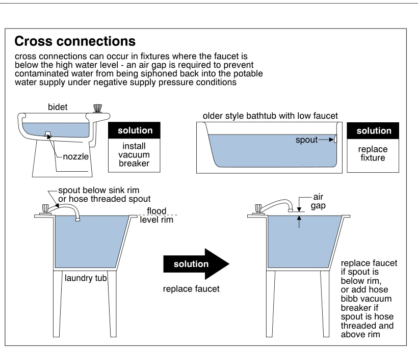
1545Cross connections
· p. 267
The illustration compares plumbing cross-connection hazards and corrective measures at a bidet, an older bathtub, and a laundry tub. The bidet has a submerged nozzle, with installation of a vacuum breaker identified as the solution. The bathtub has a low spout below the illustrated water level, and fixture replacement is recommended. The laundry tub comparison shows a spout below the flood level rim versus a replacement faucet providing an air gap above the rim. An annotation specifies a hose bibb vacuum breaker for a hose-threaded spout above the rim, and the introductory text explains the risk of contaminated water being siphoned into the potable supply under negative supply pressure.
 1546
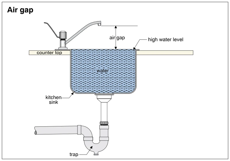
1546Air gap
· p. 267
The illustration shows a cross-section of a kitchen sink installed in a countertop, with a faucet above and a drain trap below. The sink is filled with water to the indicated high water level at its rim. A vertical double-headed arrow identifies the air gap between the faucet outlet and this water level. This open separation protects the water supply from back-siphonage of sink water. The sink drain connects through a vertical tailpiece to a P-trap and horizontal waste pipe.
 1547
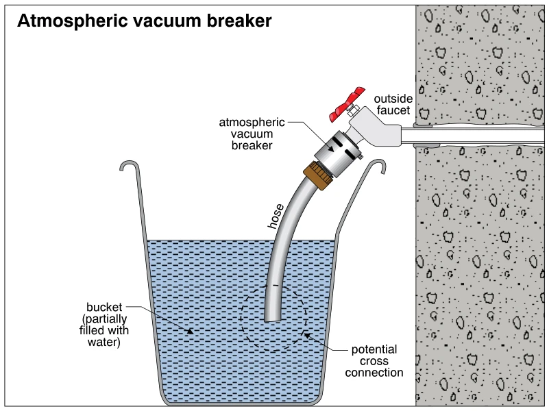
1547Atmospheric vacuum breaker
· p. 267
The illustration shows an outside faucet supplied by a pipe passing through a wall. An atmospheric vacuum breaker is installed between the faucet outlet and a hose. The hose extends into a bucket partially filled with water, with its open end submerged below the water surface. The submerged hose end is identified as a potential cross connection; the vacuum breaker provides protection against backsiphonage into the water supply.
 1548
1548Pressure type vacuum breaker
· p. 267
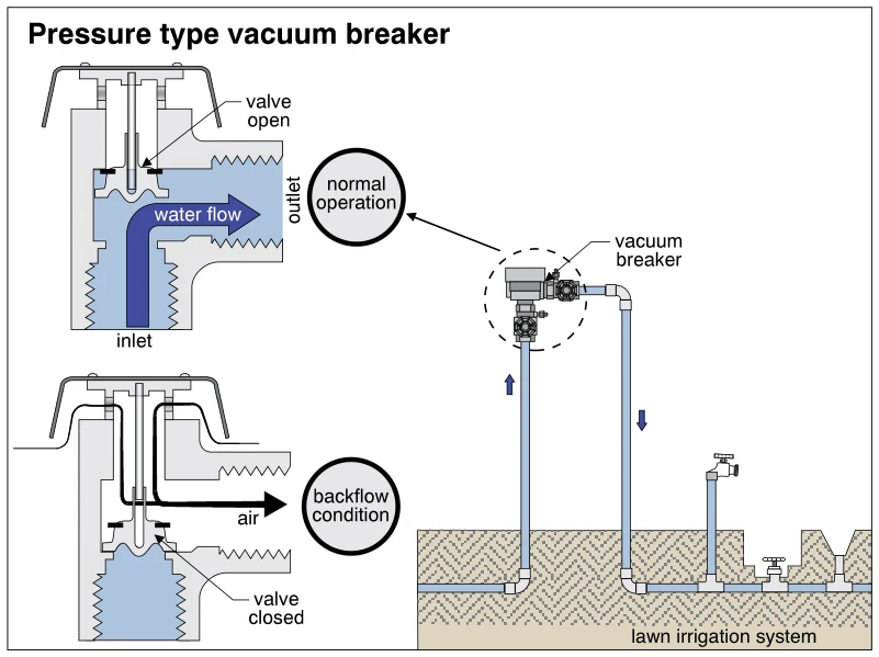
The illustration shows a pressure-type vacuum breaker installed on an elevated piping loop serving a lawn irrigation system. Arrows indicate supply water rising to the vacuum breaker and descending into the irrigation piping. An enlarged section shows normal operation with the valve open and water flowing from the bottom inlet to the side outlet. A second section shows a backflow condition, with the valve closed and air entering through the top vent and passing toward the outlet. The installation drawing also includes shutoff valves, a hose faucet, and an irrigation outlet.
 1548.5
Dual check valve assembly
· p. 267
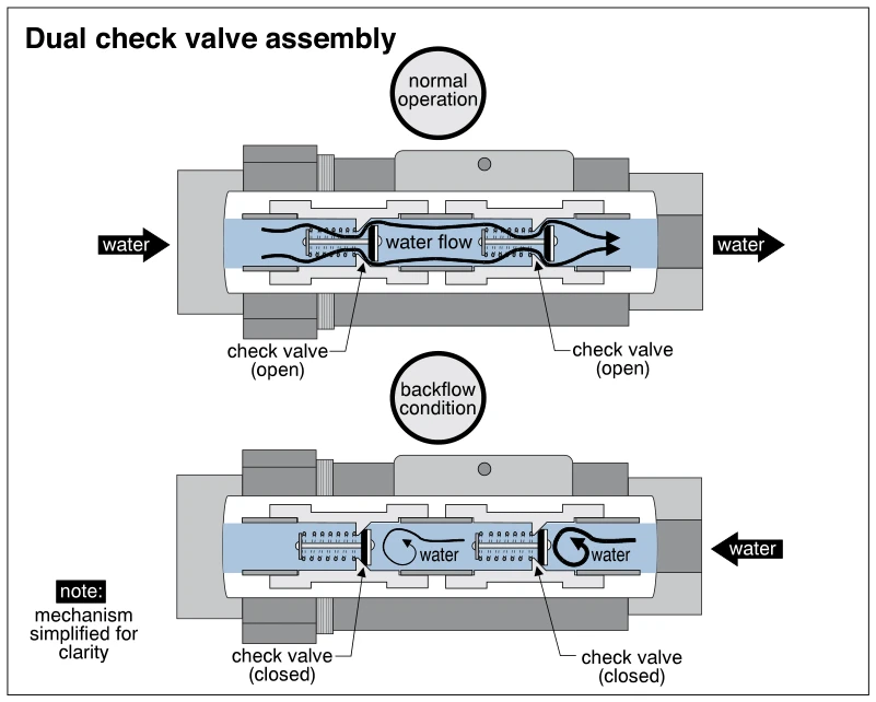
Two sectional views show a dual check valve assembly with two spring-loaded check valves arranged in series inside a common housing. In the upper view, normal water flow travels from left to right with both check valves open. In the lower view, a backflow condition is illustrated with water directed from the right and both check valves closed to prevent reverse flow. A note states that the mechanism is simplified for clarity.
 1549
1549Double check valve assembly
· p. 268
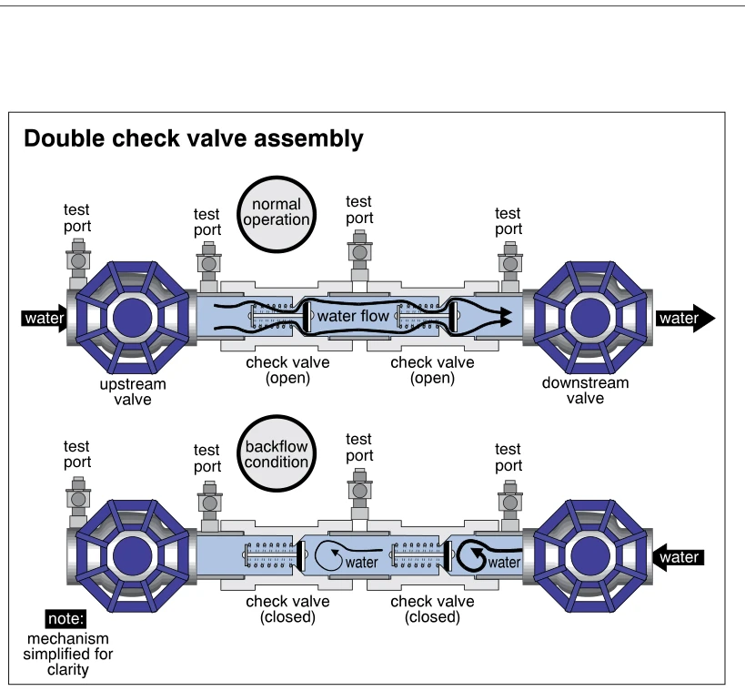
Two cutaway views depict a double check valve assembly with upstream and downstream handwheel-operated valves, two spring-loaded check valves in series, and four test ports. The upper view shows normal operation, with both check valves open and water flowing from left to right. The lower view shows a backflow condition, with reverse flow entering from the right and both check valves closed to prevent upstream backflow. A note states that the mechanism is simplified for clarity.
 1550
1550Reduced pressure backflow assembly
· p. 268
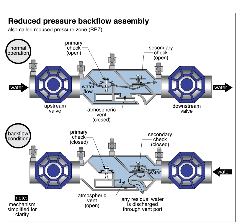
Two simplified cutaway diagrams show a reduced pressure backflow assembly between upstream and downstream shutoff valves. During normal operation, water flows from left to right through open primary and secondary check valves, while the atmospheric vent remains closed. In the backflow condition, the flow arrow points toward the assembly from the downstream side and both check valves are closed. The atmospheric vent opens, allowing residual water to discharge through the vent port. The diagrams compare operating states rather than proper and improper installations.
 1550.5
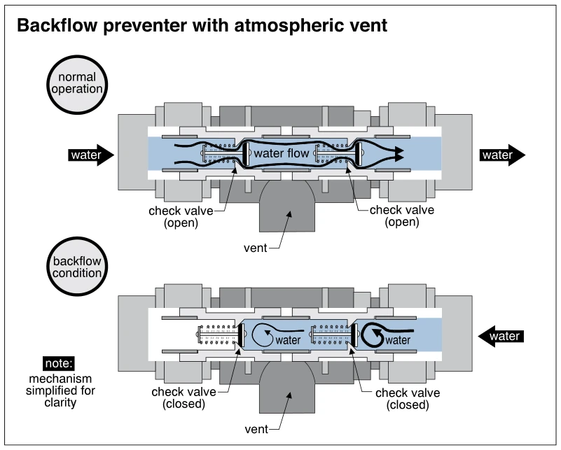
Backflow preventer with atmospheric vent
· p. 268
Two sectional diagrams show a backflow preventer with two spring-loaded check valves and an atmospheric vent beneath the intermediate chamber. During normal operation, both check valves are open and arrows show water flowing from left to right. Under the backflow condition, an arrow shows water entering from the right, and both check valves are closed to block reverse flow. The vent connection is shown below the chamber in both diagrams. A note states that the mechanism is simplified for clarity.
 1551
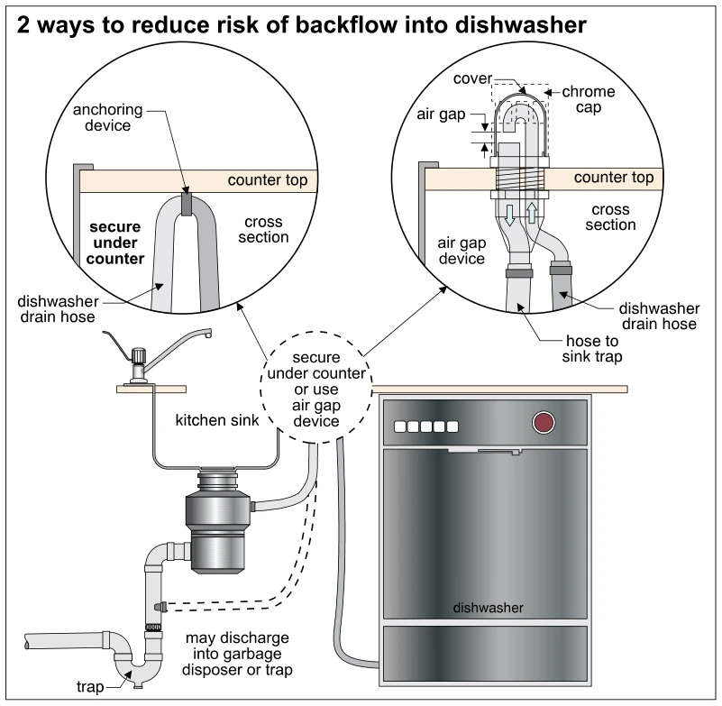
15512 ways to reduce risk of backflow into dishwasher
· p. 268
The illustration shows a dishwasher beside a kitchen sink with a garbage disposer and drain trap, with two methods of reducing drain-water backflow into the dishwasher. The left enlarged cross section shows the dishwasher drain hose formed into a high loop and secured beneath the countertop with an anchoring device. The right enlarged cross section shows a countertop-mounted air gap device with a chrome cap, separate hose connections, and arrows indicating flow through the device. The main drawing shows the dishwasher discharge routed to the garbage disposer, with a dashed alternative connection to the sink drain above the trap.
Water Heaters ·Introductionp. 269
 1552
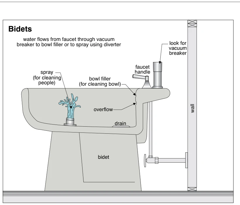
1552Bidets
· p. 269
The illustration shows a sectional side view of a floor-mounted bidet beside a wall, with a wall-mounted water supply stop and a supply line rising to the fixture. The bowl contains an upward-directed spray, a bowl filler near the rear rim, an overflow opening, and a drain. An annotation explains that water flows from the faucet through a vacuum breaker and is directed to either the bowl filler or the spray using a diverter. A callout specifically instructs the inspector to look for the vacuum breaker, shown above the rear rim beside the faucet handle.
 1553
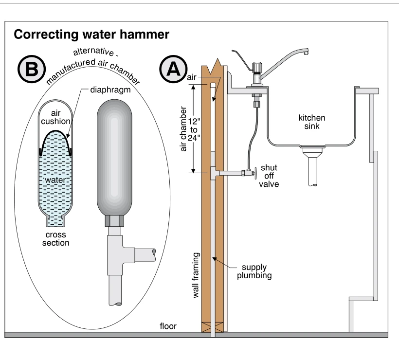
1553Correcting water hammer
· p. 269
The illustration shows two arrangements for correcting water hammer in supply plumbing. Arrangement A has a capped vertical air chamber extending 12 to 24 inches above the branch supplying a kitchen sink shutoff valve, with trapped air indicated at the top. The supply pipe and chamber are shown within the wall framing beside the sink. Arrangement B shows an alternative manufactured air chamber connected to a supply tee. Its accompanying cross section shows a diaphragm separating the water from an air cushion.
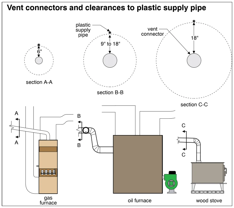 1554
1554Vent connectors and clearances to plastic supply pipe
· p. 269
The illustration compares plastic supply pipe clearances from vent connectors serving a gas furnace, an oil furnace, and a wood stove. Section cuts A-A, B-B, and C-C correspond to the vent connectors shown at the three appliances. Each section shows a small plastic supply pipe outside the vent connector, with a dimension arrow indicating separation and a dashed circle marking the clearance envelope. The indicated clearances are 6 inches for the gas furnace, 9 to 18 inches for the oil furnace, and 18 inches for the wood stove. No damaged piping or clearance violation is depicted.
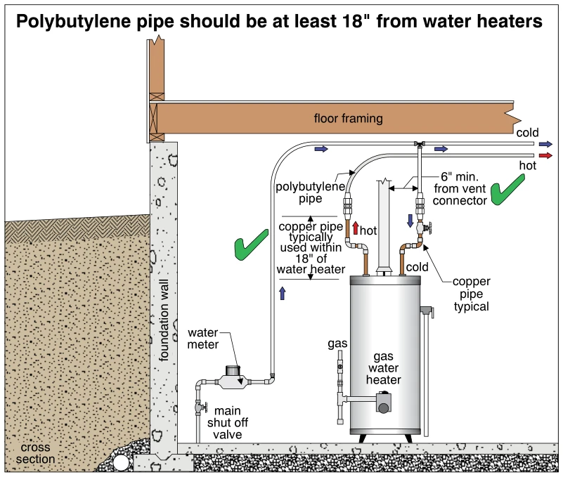 1555
1555Polybutylene pipe should be at least 18" from water heaters
· p. 269
The illustration shows a cross section of basement supply plumbing serving a gas water heater beneath floor framing. The incoming water supply passes through a main shutoff valve and water meter before rising to the cold-water distribution line and heater branch. Copper piping connects the heater's hot and cold connections to polybutylene piping, with an annotation specifying copper typically within 18 inches of the water heater. A separate dimension specifies a minimum 6-inch clearance from the vent connector to the nearby piping. Green check marks identify these separation practices as correct, and colored arrows indicate hot- and cold-water flow.
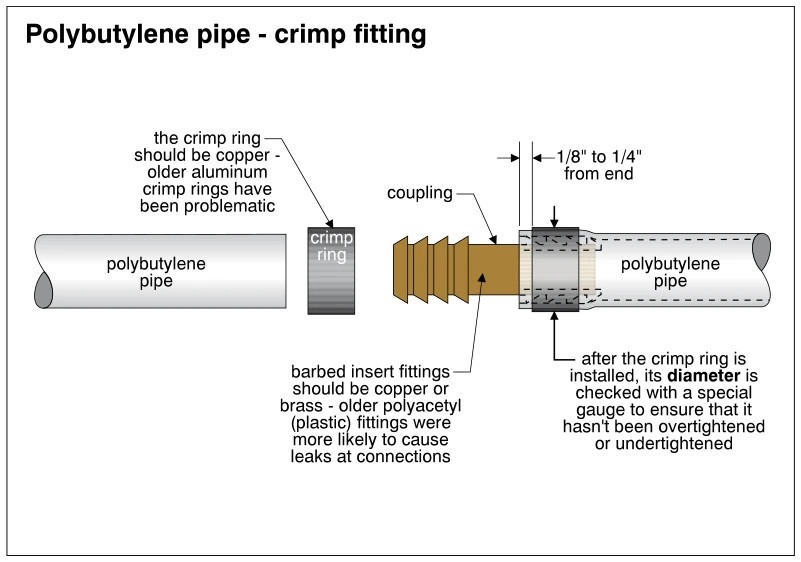 1556
1556Polybutylene pipe - crimp fitting
· p. 269
The illustration shows a partially exploded crimp connection for polybutylene water-supply pipe, with a loose pipe section and crimp ring beside a barbed coupling inserted into another pipe section. The installed ring is positioned 1/8 inch to 1/4 inch from the pipe end. Annotations specify copper crimp rings and copper or brass barbed insert fittings, noting problems with older aluminum rings and increased leakage risk with older polyacetyl plastic fittings. The installed ring diameter is to be checked with a special gauge to verify that the connection is neither overtightened nor undertightened.
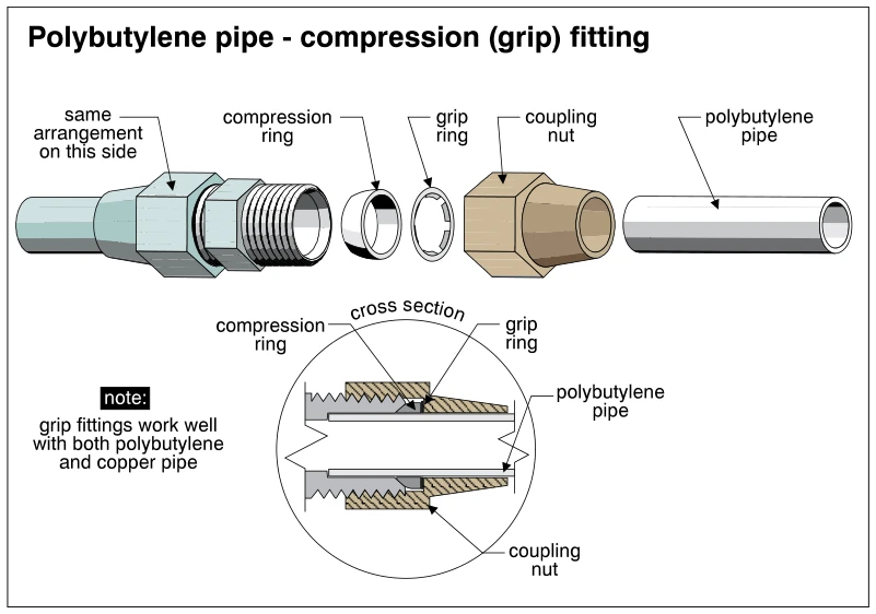 1557
1557Polybutylene pipe - compression (grip) fitting
· p. 269
The illustration shows an exploded view of a compression (grip) fitting for polybutylene supply pipe. A compression ring, grip ring, and coupling nut are aligned between the threaded fitting body and the pipe end. A callout indicates that the opposite side of the fitting uses the same arrangement. A circular cross section shows the rings surrounding the inserted pipe within the tightened coupling nut. A printed note states that grip fittings work well with both polybutylene and copper pipe; no defect is depicted.
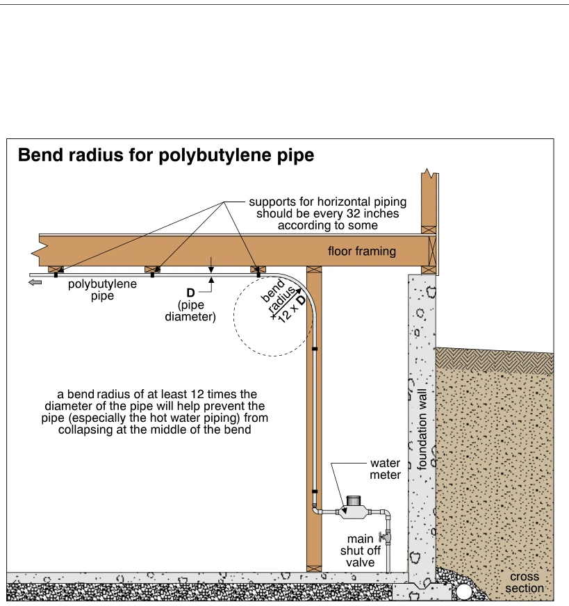 1558
1558Bend radius for polybutylene pipe
· p. 270
A building cross section shows polybutylene supply piping rising from a water meter and bending into a horizontal run beneath wood floor framing. The bend radius is marked as 12 times the pipe diameter, with a note explaining that this minimum radius helps prevent collapse at the middle of the bend, especially in hot-water piping. Supports secure the horizontal pipe beneath the framing, and an annotation states that supports should be every 32 inches according to some. The lower portion shows the water meter and main shutoff valve beside a foundation wall, with the floor slab and exterior soil also visible.
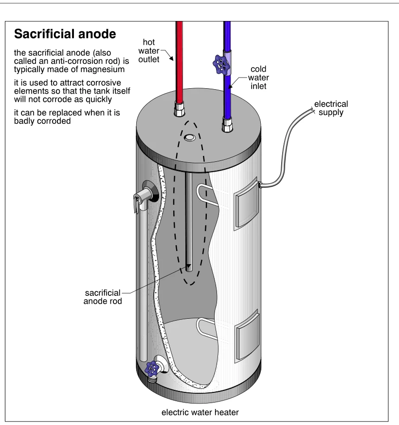 1559
1559Sacrificial anode
· p. 270
A cutaway of an electric storage water heater shows a sacrificial anode rod suspended vertically inside the tank from its top. The drawing also shows hot and cold water connections, a cold-water shutoff valve, electrical supply, two heating elements with exterior access covers, and a drain valve near the bottom. A dashed outline emphasizes the anode rod. The annotations explain that the rod is typically magnesium, protects the tank against corrosion, and can be replaced when badly corroded.
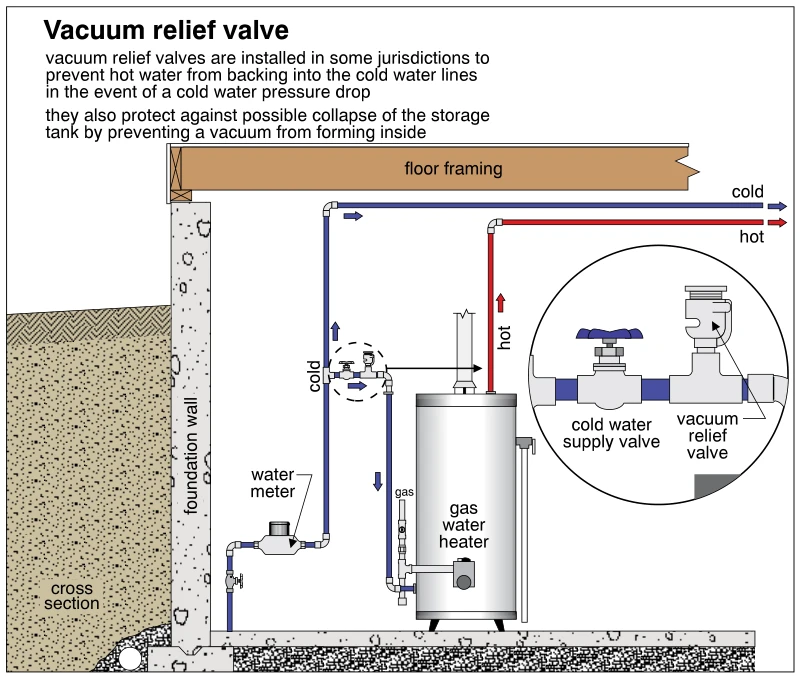 1560
1560Vacuum relief valve
· p. 270
A basement cross section shows a gas water heater connected to blue cold-water piping and red hot-water piping beneath the floor framing. The incoming water service passes through a water meter and branches to the cold-water distribution line and the heater supply. An enlarged detail shows a vacuum relief valve installed on the heater's cold-water supply, downstream of the cold-water supply valve. Arrows indicate water flow through the piping. The annotations explain that the vacuum relief valve prevents hot water from backing into cold-water lines during a cold-water pressure drop and protects the storage tank against collapse caused by a vacuum.
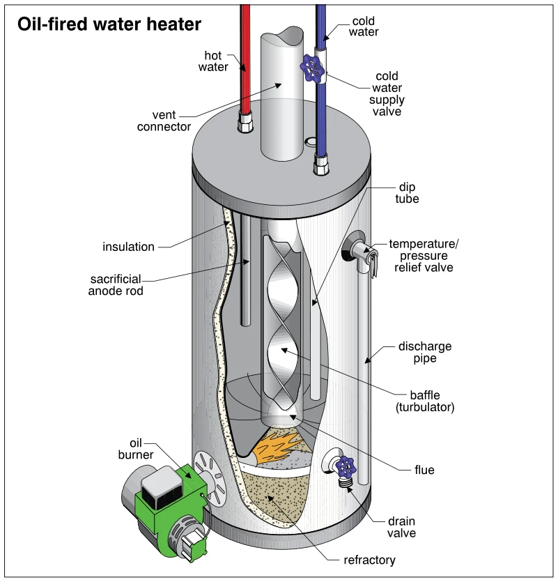 1561
1561Oil-fired water heater
· p. 270
The illustration shows a cutaway of an oil-fired storage water heater with an external oil burner firing into a refractory-lined combustion chamber below the tank. A central flue containing a twisted baffle (turbulator) passes upward through the tank and connects to the vent connector at the top. The cold-water inlet has a supply valve and an internal dip tube extending toward the bottom of the tank, while the hot-water outlet exits at the top. Insulation surrounds the tank, and a sacrificial anode rod hangs inside it. A side-mounted temperature/pressure relief valve connects to a downward discharge pipe, and a drain valve is located near the bottom.
Water Heaters ·Gas Piping, Burners and Ventingp. 271
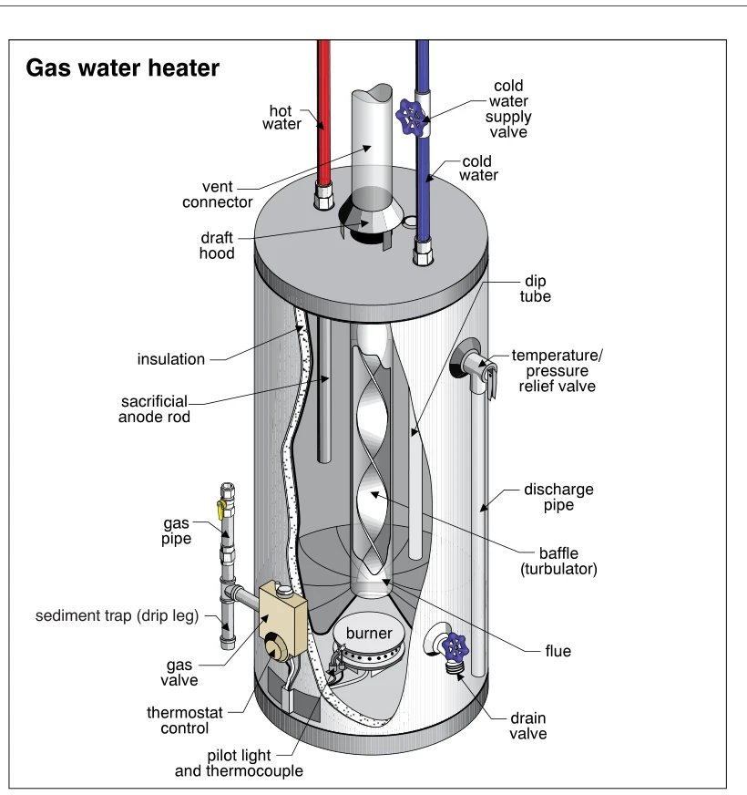 1562
1562Gas water heater
· p. 271
A cutaway drawing shows a storage-type gas water heater with an insulated tank and a burner beneath it. The cold-water supply connects to a dip tube extending toward the bottom of the tank, while the hot-water outlet leaves the top. A central flue containing a baffle carries combustion gases upward to the draft hood and vent connector. The gas supply includes a sediment trap and gas valve, with thermostat control, pilot light, and thermocouple shown near the burner. A sacrificial anode rod, temperature/pressure relief valve with discharge pipe, and lower drain valve are also identified.
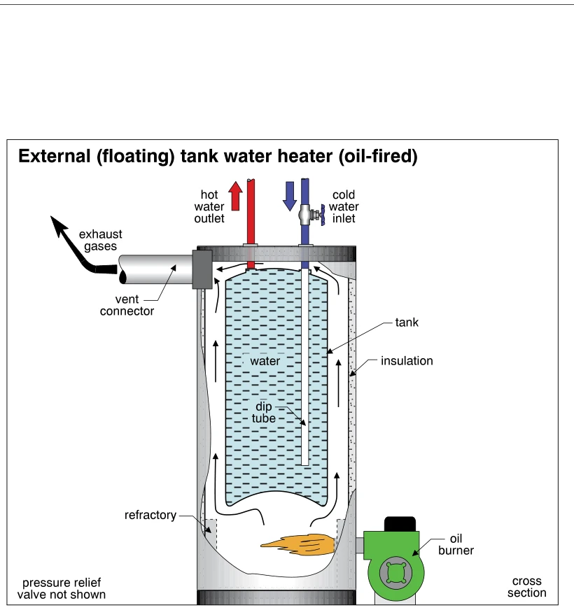 1563
1563External (floating) tank water heater (oil-fired)
· p. 271
A cross section shows an oil-fired water heater with an internal water tank surrounded by an external combustion-gas passage. An oil burner fires into a refractory-lined chamber beneath the tank, and arrows show hot gases rising around the tank sides and exiting through a vent connector near the top. Cold water enters at the top and travels down a dip tube, while hot water leaves through a separate top outlet. Insulation is shown along the outer enclosure. A note states that the pressure relief valve is not shown.
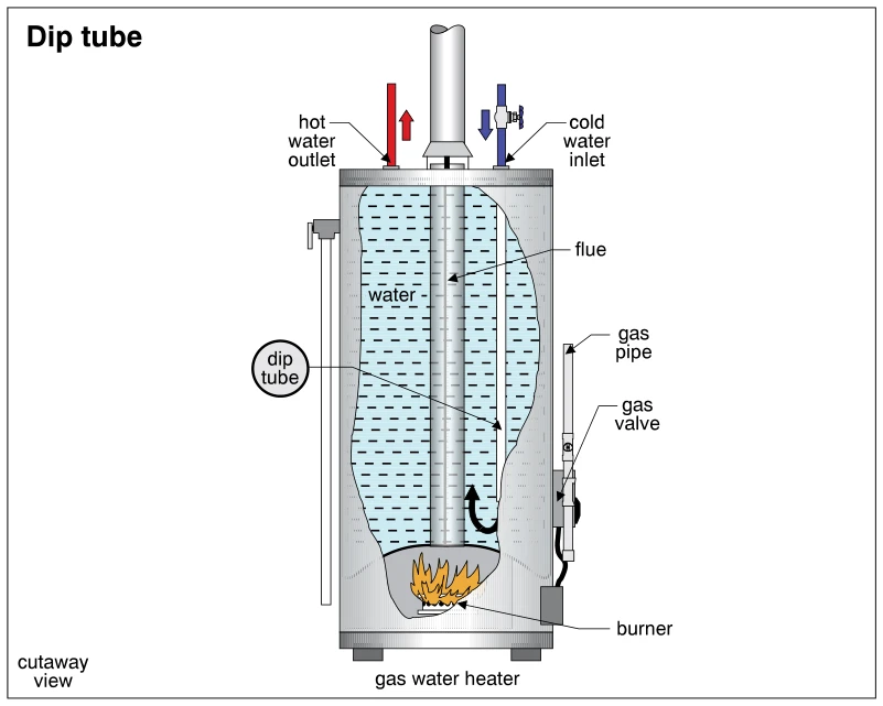 1564
1564Dip tube
· p. 271
A cutaway view of a gas-fired storage water heater shows the dip tube extending from the top cold-water inlet to near the bottom of the tank. Arrows indicate cold water entering at the top, discharging near the bottom, and circulating upward as it is heated. Hot water exits through a separate outlet at the top. A gas pipe and gas valve supply the burner beneath the tank, and a central flue extends upward through the stored water to the vent above. No defect is depicted.
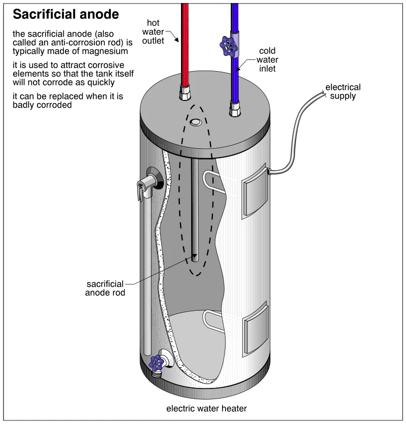 1565
1565Sacrificial anode
· p. 271
A cutaway view of an electric storage water heater shows a sacrificial anode rod suspended vertically inside the tank from its top. A dashed outline emphasizes the rod, and the annotations explain its corrosion-protection function, typical magnesium construction, and replacement when badly corroded. The top has a hot-water outlet and a cold-water inlet with a shutoff valve. Two heating elements, exterior access covers, an electrical supply connection, a side-mounted relief valve with discharge pipe, and a bottom drain valve are also visible. No actual corrosion damage or installation defect is depicted.
 1566
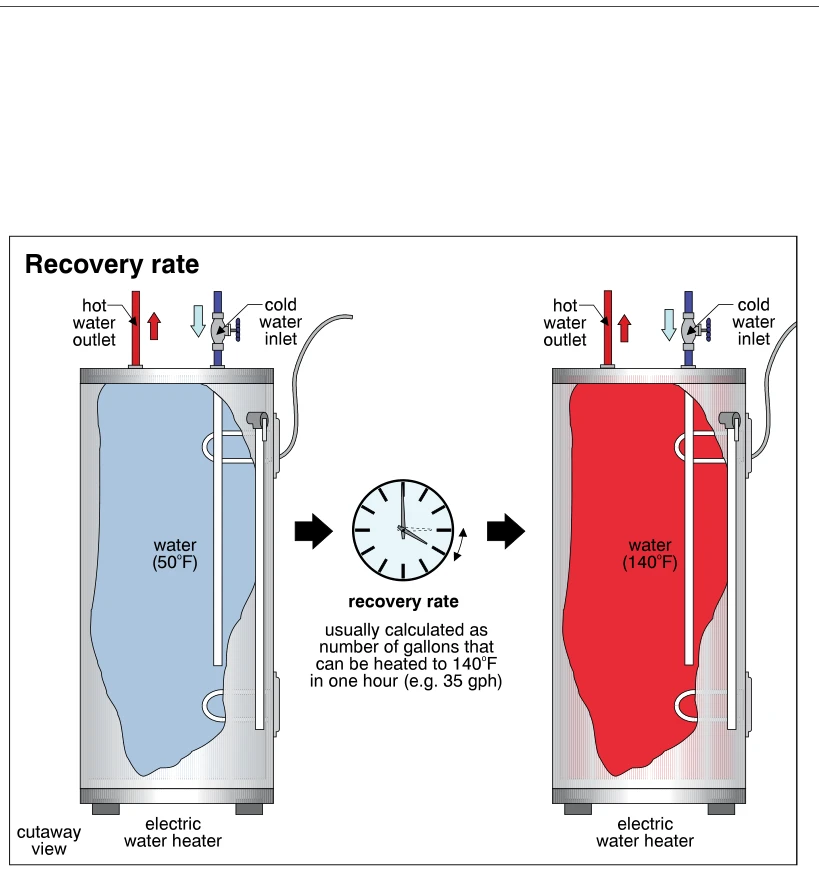
1566Recovery rate
· p. 272
Two cutaway views of an electric storage water heater illustrate recovery rate as water is heated from 50°F to 140°F. Each tank shows a top-mounted cold-water inlet with a dip tube extending toward the bottom, a hot-water outlet, and upper and lower electric heating elements. Blue water in the left tank and red water in the right tank indicate the temperature change, with arrows and a clock between them representing elapsed heating time. The annotation describes recovery rate as the number of gallons that can be heated to 140°F in one hour, giving 35 gallons per hour as an example.
 1567
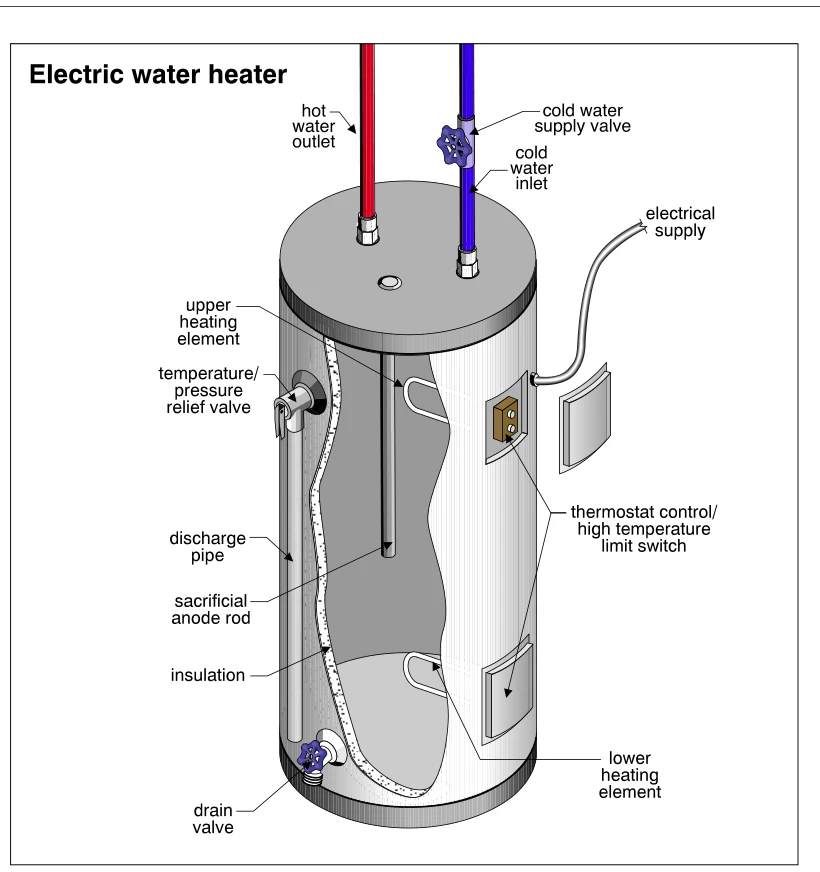
1567Electric water heater
· p. 272
The illustration shows a cutaway of a cylindrical electric storage water heater with an insulated tank and outer jacket. Hot water exits at the top beside a cold water inlet fitted with a supply shutoff valve. Upper and lower electric heating elements project into the tank, with side access panels and a labeled thermostat control/high temperature limit switch. A sacrificial anode rod extends downward inside the tank. A side-mounted temperature/pressure relief valve connects to a downward discharge pipe, and a drain valve is located near the bottom.
 1567.5
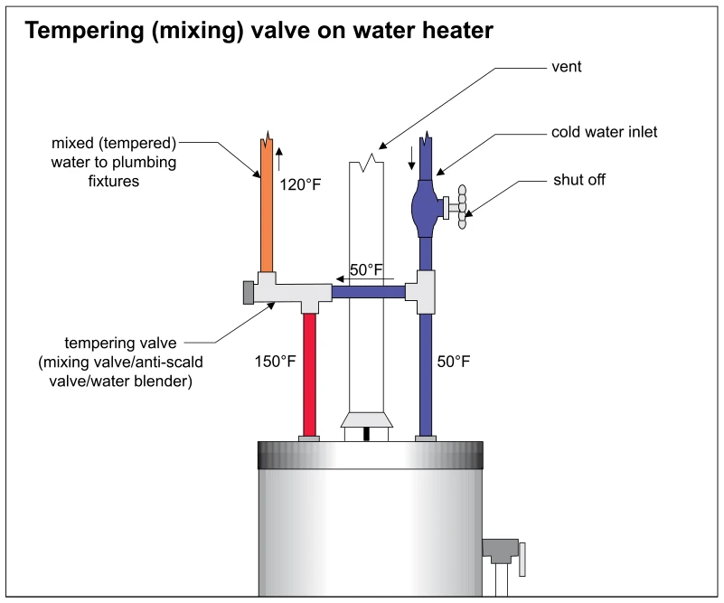
Tempering (mixing) valve on water heater
· p. 272
The illustration shows a water heater with a tempering valve connecting its hot-water outlet to a branch from the cold-water inlet. Blue piping carries 50°F cold water into the tank and toward the mixing valve, while red piping carries 150°F water from the tank to the valve. The valve delivers mixed water at 120°F through an orange outlet leading to plumbing fixtures. A shutoff valve is shown on the cold-water supply upstream of the branch, and a vent rises from the center of the water heater.
 1568
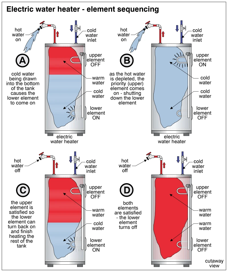
1568Electric water heater - element sequencing
· p. 272
Four cutaway views show the operating sequence of a dual-element electric storage water heater, with red indicating warm water and blue indicating cold water. In stage A, hot water is being drawn and incoming cold water reaches the tank bottom through a dip tube, causing the lower element to turn on while the upper element remains off. In stage B, depletion of hot water activates the priority upper element and shuts off the lower element. In stage C, the hot-water draw has stopped and the upper element is satisfied, allowing the lower element to resume heating the remaining cold water. In stage D, the tank contains warm water and both elements are off.
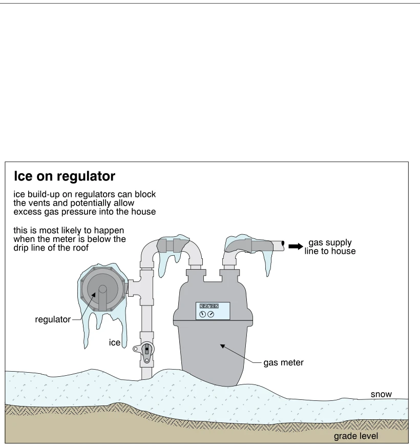 1569
1569Ice on regulator
· p. 273
The illustration shows an exterior gas meter connected to a pressure regulator, a shutoff valve, and gas piping leading to the house. Ice coats the regulator and portions of the overhead piping, with icicles hanging from them. Snow covers the ground around the base of the meter assembly. The annotations warn that ice buildup can block regulator vents and potentially allow excessive gas pressure into the house, particularly when the meter is below the roof drip line.
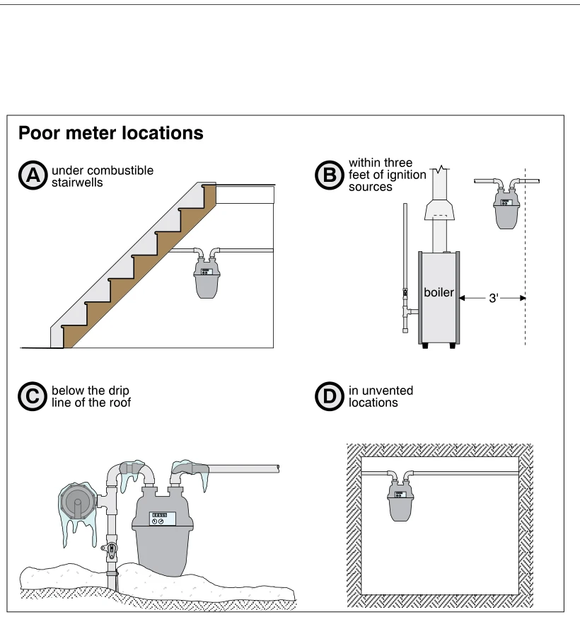 1570
1570Poor meter locations
· p. 273
Four diagrams illustrate improper gas meter locations. Panel A places a meter beneath a combustible stairwell. Panel B shows a meter within three feet of a boiler, identified as an ignition source. Panel C depicts a meter and associated piping below the roof drip line, with ice hanging from the piping and regulator and snow beneath the assembly. Panel D shows a meter inside an unvented enclosure.
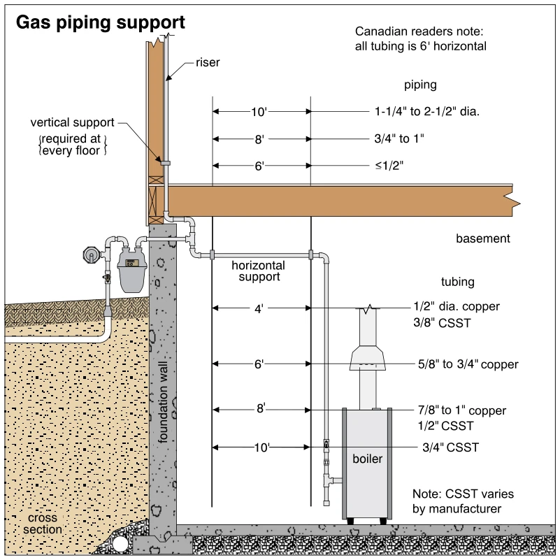 1571
1571Gas piping support
· p. 273
A building cross-section shows gas service piping passing through a foundation wall, with a vertical riser and a supported horizontal basement run supplying a boiler. The riser is secured to framing, with an annotation requiring vertical support at every floor. Horizontal piping support intervals are shown as 6, 8, or 10 feet according to pipe diameter. A separate tubing chart gives intervals of 4, 6, 8, or 10 feet for specified copper and CSST sizes. Notes state that CSST requirements vary by manufacturer and that Canadian readers should use 6-foot horizontal support spacing for all tubing.
 1572
1572Sediment trap
· p. 273
The illustration shows a gas-fired storage water heater with hot and cold water connections, a cold water supply valve, and a draft hood beneath the vent connector. Gas piping descends beside the heater to a tee, whose horizontal branch connects to the gas valve and thermostat control assembly. A capped vertical pipe extends below the tee to form a sediment trap, shown enlarged in a circular detail. The annotation explains that this trap collects sediment to reduce the chance of clogged gas valves or burners.
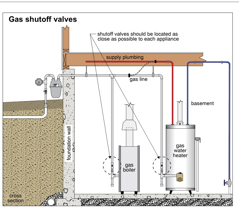 1573
1573Gas shutoff valves
· p. 274
This cross-sectional illustration shows an exterior gas meter supplying a gas line through a foundation wall into a basement. The gas line branches down to a gas boiler and a gas water heater, with individual shutoff valves highlighted near each appliance. An annotation specifies that shutoff valves should be located as close as possible to each appliance. Both appliance connections include a tee with a capped downward pipe extension below the valve. Water supply piping and vent connections are also shown.
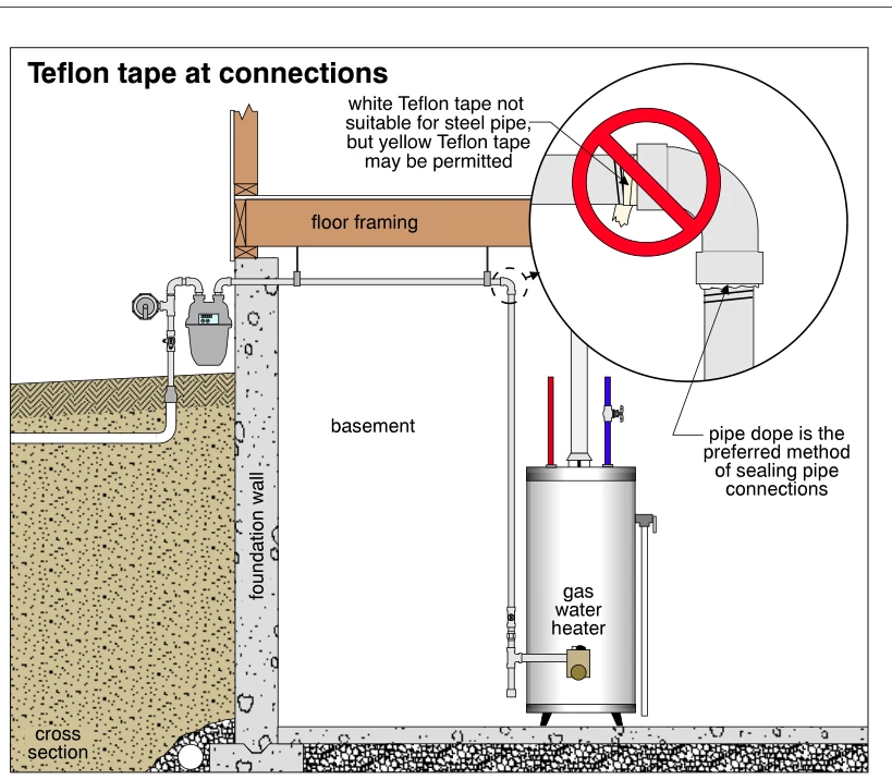 1574
1574Teflon tape at connections
· p. 274
The cross section shows an exterior gas meter supplying a basement gas water heater through piping routed beneath the floor framing and down beside the heater. A magnified inset shows threaded steel pipe connections at an elbow, with a red prohibition symbol over a tape-wrapped joint. The annotation states that white Teflon tape is not suitable for steel pipe, but yellow Teflon tape may be permitted. A separate arrow identifies pipe dope as the preferred method of sealing the pipe connections.
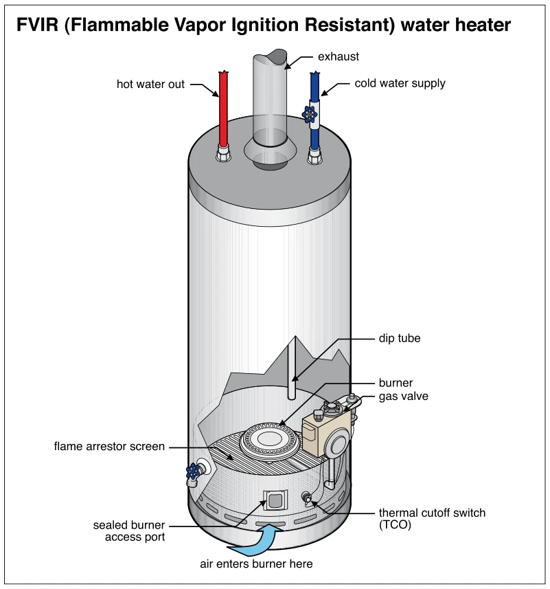 1574.5
FVIR (Flammable Vapor Ignition Resistant) water heater
· p. 274
The illustration shows a cutaway of a flammable vapor ignition resistant (FVIR) gas-fired storage water heater. Hot-water outlet and cold-water supply connections flank the exhaust vent at the top, and an internal dip tube extends toward the bottom of the tank. The lower cutaway exposes the burner and flame arrestor screen, with a gas valve mounted on the exterior. A sealed burner access port and thermal cutoff switch are identified near the base, where an arrow indicates incoming burner air. No defect or improper installation is depicted.
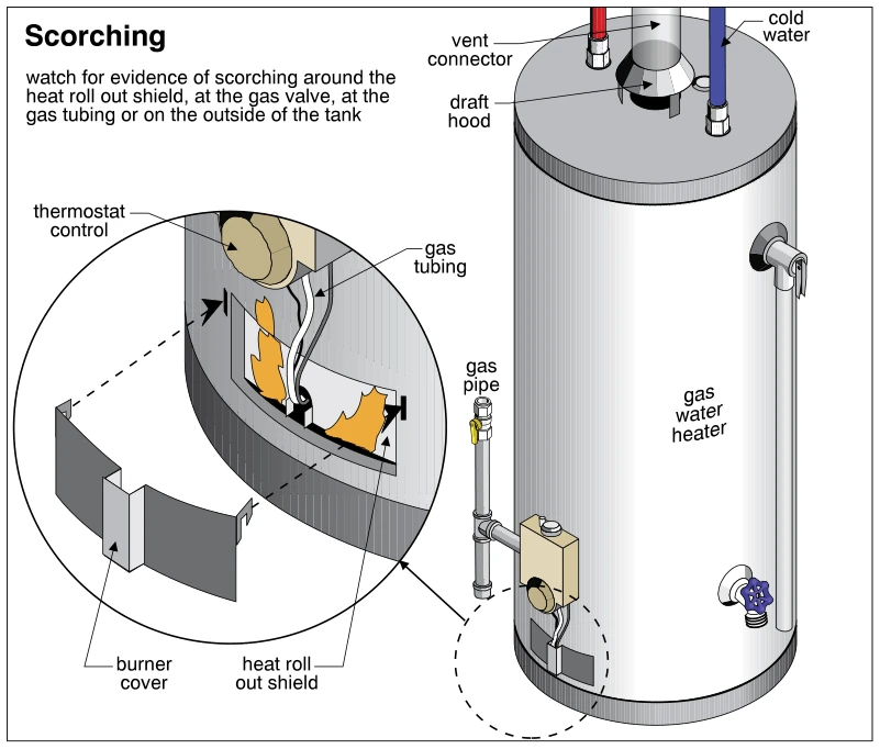 1575
1575Scorching
· p. 274
The illustration shows a gas-fired storage water heater with a top-mounted draft hood and vent connector, cold-water connection, and external gas supply piping. A magnified detail shows the lower burner access area with the burner cover removed, exposing the heat roll out shield and gas tubing below the thermostat control. Orange flame shapes extend outward at the burner opening, illustrating a flame rollout hazard. The annotation directs inspectors to look for scorching around the shield, gas valve, gas tubing, and exterior of the tank.
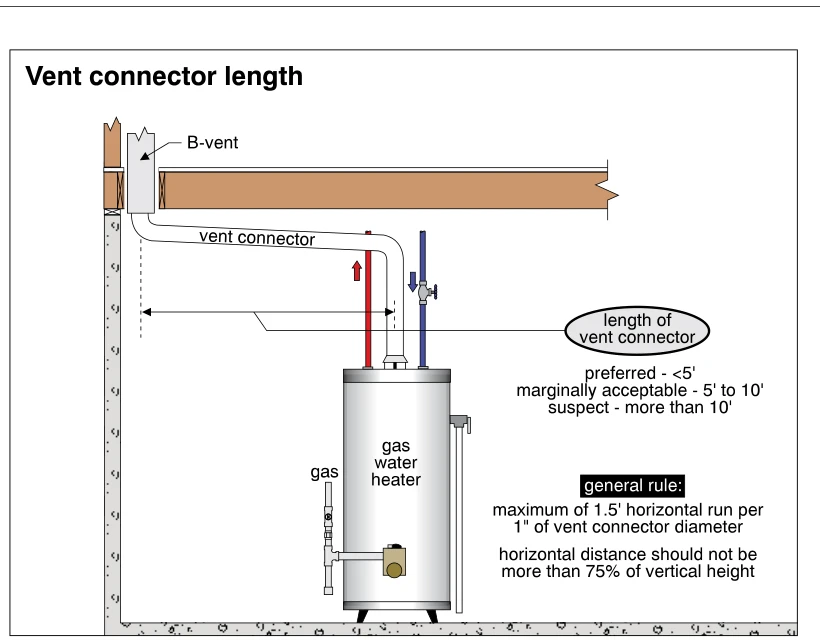 1576
1576Vent connector length
· p. 275
The illustration shows a gas-fired tank water heater connected to a vertical B-vent by a vent connector that rises above the heater and turns toward the wall beneath floor framing. A horizontal dimension line indicates the connector length between the heater connection and the B-vent. Annotations identify lengths under 5 feet as preferred, 5 to 10 feet as marginally acceptable, and more than 10 feet as suspect. Additional notes state a maximum horizontal run of 1.5 feet per inch of connector diameter and a horizontal distance no greater than 75% of the vertical height. Gas piping, hot and cold water connections, and a side-mounted relief valve with a discharge pipe are also shown.
 1577
1577Poor connections
· p. 275
The illustration shows a gas water heater connected to a vertical B-vent by a metal vent connector with several elbows and joints. The connector crosses toward the wall with an uneven slope and a low point along its run. Dashed circles highlight joints to check for disconnected sections and the presence of three screws at each connection point. An annotation warns that inadequate support can cause improper slope and low points where condensation collects. Gas piping and hot- and cold-water piping are also shown at the heater.
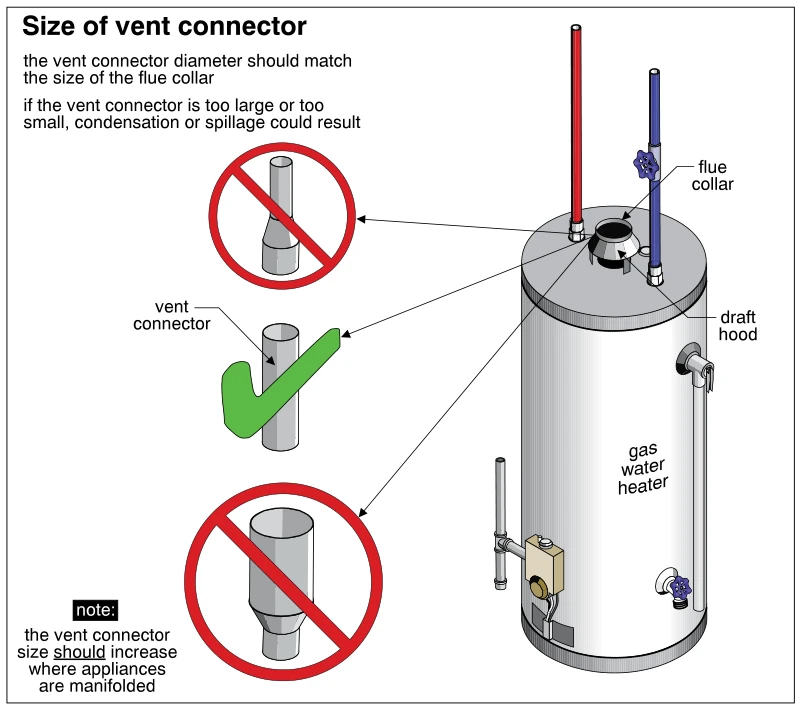 1579
1579Size of vent connector
· p. 275
The illustration shows a gas water heater with a draft hood and flue collar at its top. Three detached vent connector examples compare connector diameters relative to the flue collar. A straight connector matching the collar diameter has a green check mark, while reduced- and enlarged-diameter connectors have red prohibition symbols. Annotations warn that an oversized or undersized connector can cause condensation or combustion-gas spillage. A separate note states that vent connector size should increase where appliances are manifolded.
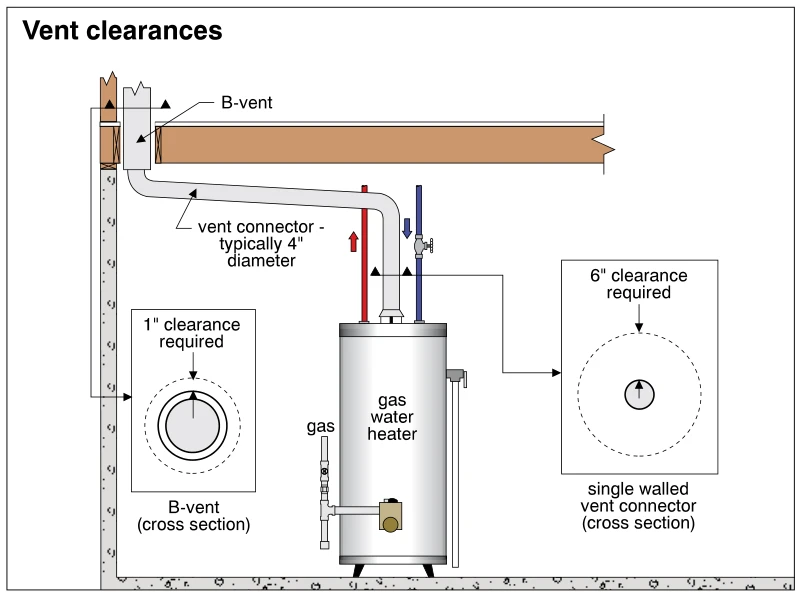 1578
1578Vent clearances
· p. 275
A gas water heater is connected to a vertical B-vent by a single-walled vent connector labeled as typically 4 inches in diameter. The connector rises from the heater and turns toward the B-vent near wood framing. Cross-section details indicate a required 1-inch clearance around the B-vent and a required 6-inch clearance around the single-walled connector. The drawing also shows the heater's gas supply, hot and cold water piping, and a side-mounted relief valve with a discharge pipe extending toward the floor.
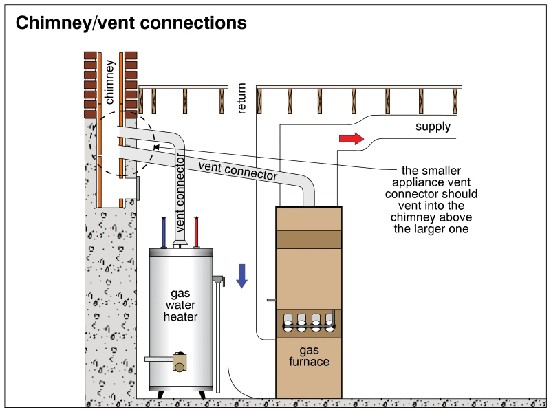 1580
1580Chimney/vent connections
· p. 275
The illustration shows a gas water heater and a gas furnace venting through separate vent connectors into a shared masonry chimney. The smaller water-heater vent connector enters the chimney above the larger furnace vent connector, as the annotation specifies. Both connectors rise toward the chimney from their respective appliances. The furnace is also shown with return and supply ductwork, with arrows indicating airflow.
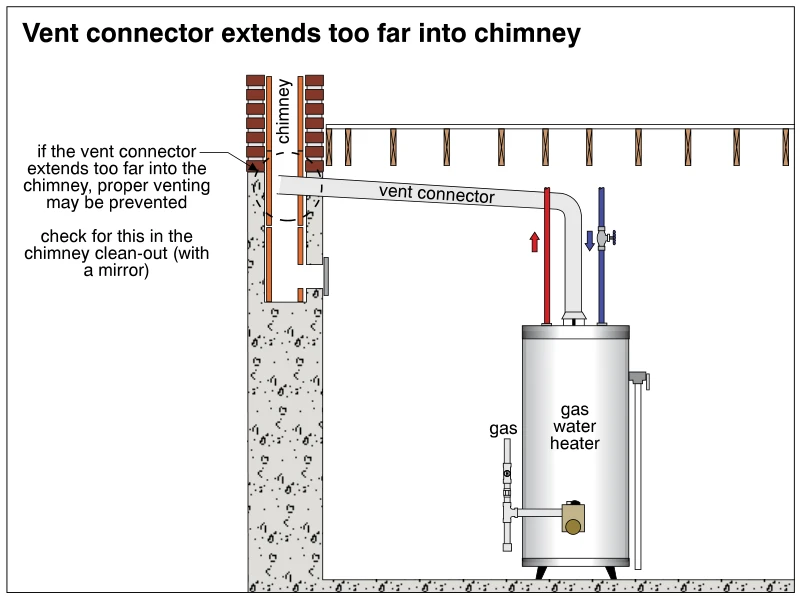 1581
1581Vent connector extends too far into chimney
· p. 275
The illustration shows a gas water heater connected to a masonry chimney by a vent connector that rises from the heater and slopes upward toward the chimney. The connector projects too far into the chimney flue, restricting the passage available for exhaust gases. A chimney clean-out is shown below the connector entry, and the annotation recommends checking the projection through this opening with a mirror. Hot and cold water piping, a cold-water shutoff valve, and gas supply piping are also shown at the heater.
Water Heaters ·Oil Tanks, Burners and Ventingp. 276
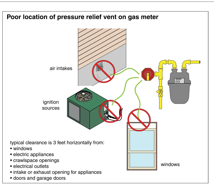 1581.5
Poor location of pressure relief vent on gas meter
· p. 276
The illustration shows a gas meter, connected gas piping, a shutoff valve, and a pressure regulator with a relief vent. Green lines extend from the vent toward a wall air intake, an electrical connection beside an outdoor appliance, and a window. Red prohibition symbols identify these nearby openings and ignition sources as inappropriate locations for a gas relief discharge. The annotation specifies a typical horizontal clearance of 3 feet from windows, electric appliances, crawlspace openings, electrical outlets, appliance intake or exhaust openings, and doors and garage doors.
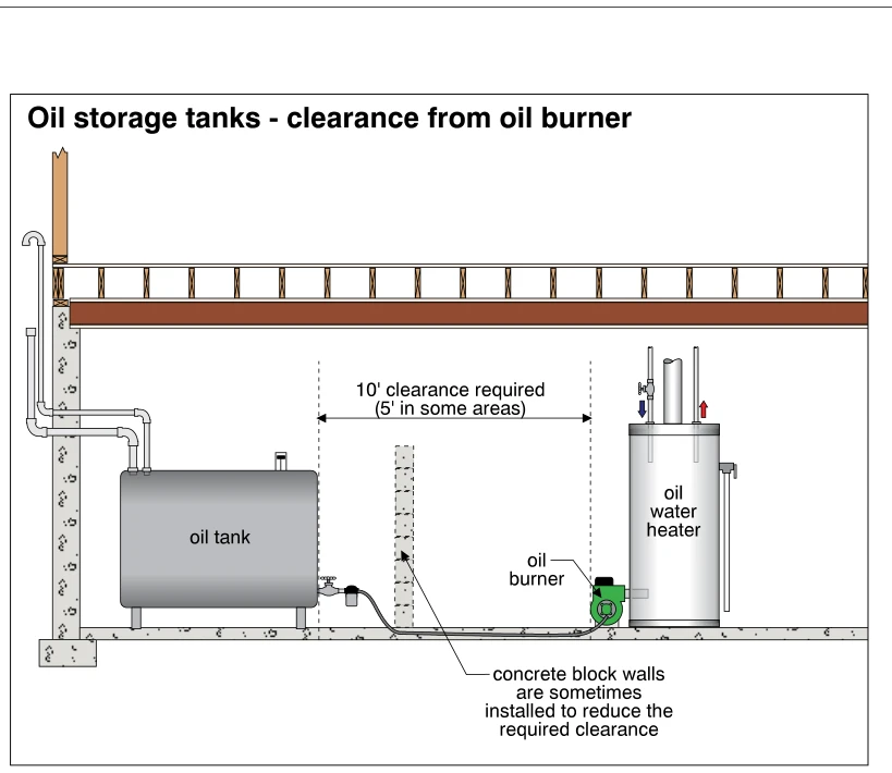 1582
1582Oil storage tanks - clearance from oil burner
· p. 276
The illustration shows an indoor oil storage tank supplying an oil burner on a water heater through a low-level fuel line. Tank fill and vent piping pass through the foundation wall, and the tank stands on legs above the concrete floor. A horizontal dimension indicates 10 feet of clearance between the tank and burner, with 5 feet noted for some areas. A short concrete block wall is shown between the tank and burner, with an annotation explaining that such walls are sometimes installed to reduce the required clearance.
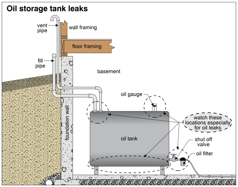 1583
1583Oil storage tank leaks
· p. 276
The illustration shows a basement oil storage tank beside a foundation wall, with fill and vent pipes passing through the wall to the exterior. An oil gauge is mounted on top of the tank, and a shutoff valve and oil filter connect to an outlet near its bottom. Dashed outlines and arrows identify the top pipe connections, gauge connection, tank bottom, and outlet valve/filter assembly as locations to check especially for oil leaks. The tank stands on legs above the basement floor; no active leakage is explicitly shown.
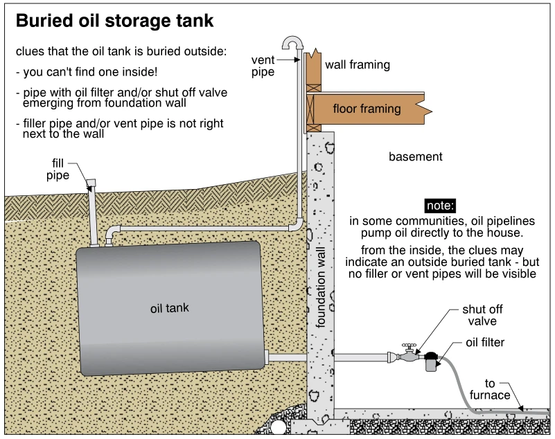 1584
1584Buried oil storage tank
· p. 276
A sectional drawing shows an oil storage tank buried outside a basement foundation wall. A fill pipe rises from the tank above grade, while a separate vent pipe runs underground toward the house and rises alongside the exterior wall to a downturned termination. An oil supply pipe passes through the foundation wall into the basement, with a shutoff valve and oil filter before the line continues toward the furnace. Wood wall and floor framing are shown above the foundation. Annotations identify clues to a buried tank and explain that a direct community oil pipeline can produce similar interior clues without visible fill or vent pipes.
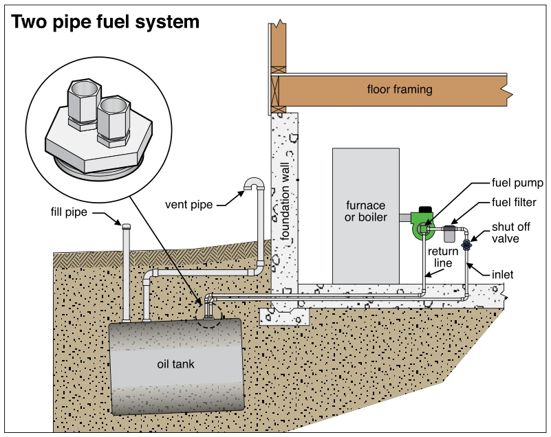 1584.5
Two pipe fuel system
· p. 276
A cutaway shows an underground oil tank outside a foundation wall connected to an indoor furnace or boiler by a two-pipe fuel system. The inlet and return lines run from the tank through the foundation area to the fuel pump at the heating appliance. A fuel filter and shut off valve are shown on the inlet piping near the pump. Separate fill and vent pipes extend from the tank above exterior grade, with the vent terminating in a downturned fitting. A circular inset enlarges the two-connection fitting at the top of the tank.
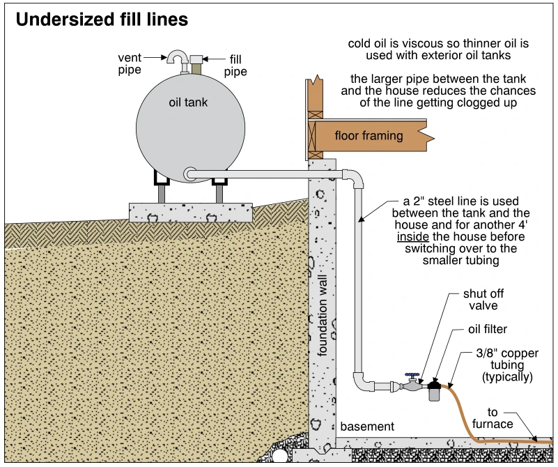 1585
1585Undersized fill lines
· p. 276
The illustration shows an exterior oil tank supported on a concrete pad beside a house, with fill and vent pipes at the top. A supply line leaves the lower portion of the tank, passes through the foundation wall, and turns downward into the basement. The annotations specify a 2-inch steel line between the tank and house and for another 4 feet inside before transitioning to smaller tubing. A shutoff valve and oil filter precede the typical 3/8-inch copper tubing leading to the furnace. Although titled "Undersized fill lines," the drawing explains how a larger supply pipe reduces clogging associated with viscous cold oil.
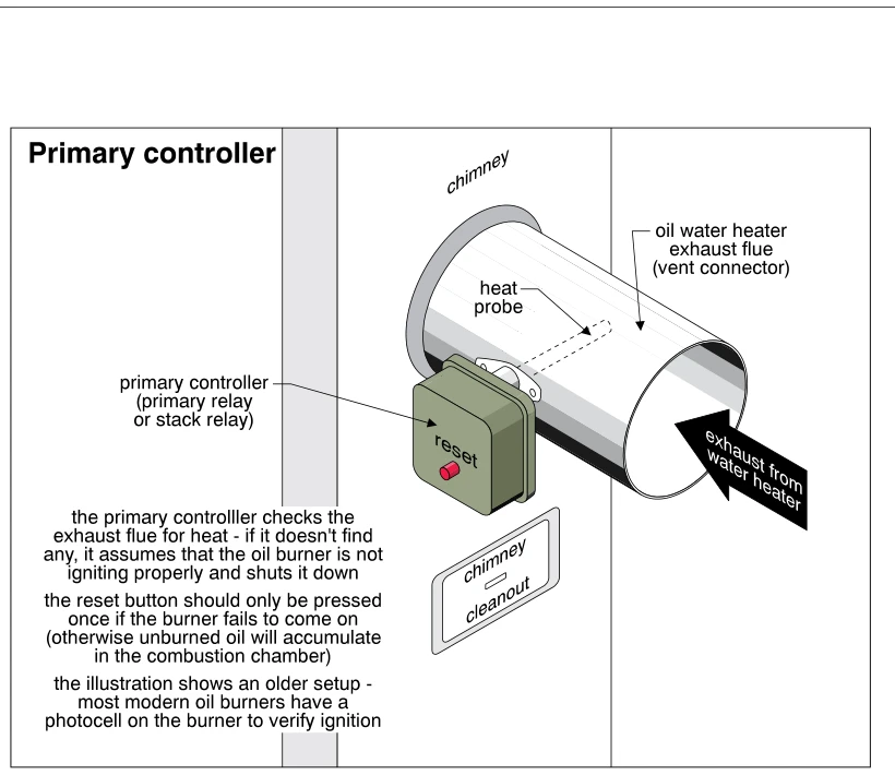 1586
1586Primary controller
· p. 277
The illustration shows an older oil-fired water heater vent connector entering a chimney, with a primary controller mounted beside the connector. A heat probe projects into the exhaust path to detect heat as evidence of burner ignition. The controller has a reset button, and a chimney cleanout is shown below the connection. Annotations explain that the controller shuts down the burner if exhaust heat is absent and warn against pressing the reset button more than once because unburned oil can accumulate in the combustion chamber. The illustration contrasts this older heat-sensing arrangement with modern burners that use a photocell to verify ignition.
 1587
1587Refractory/fire pot
· p. 277
The illustration shows a cross section of an oil-fired water heater and an enlarged perspective of its refractory fire pot and oil burner. The burner fires horizontally into the refractory-lined combustion chamber beneath the water tank, with a central flue extending upward through the tank. Hot- and cold-water connections are shown at the top, with the cold-water dip tube extending down into the tank. The perspective view depicts a crack and localized deterioration in the refractory material, with an annotation directing inspection for these conditions.
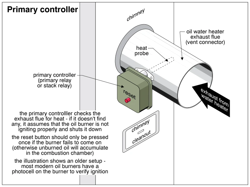 1588
1588Primary controller
· p. 277
The illustration shows an older oil-fired water heater primary controller mounted on the exhaust vent connector entering a chimney. A heat probe extends into the connector to detect heat from the water heater exhaust, and the controller has a reset button. The annotations explain that the controller shuts down the burner if exhaust heat is not detected, indicating unsuccessful ignition. They warn against pressing the reset button more than once when the burner fails to start because unburned oil can accumulate in the combustion chamber. A chimney cleanout is shown below the connection, and a note contrasts this older stack-relay arrangement with modern burner-mounted photocell ignition verification.
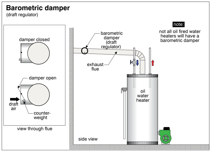 1589
1589Barometric damper
· p. 277
The illustration shows an oil-fired water heater with an exhaust flue rising from its top and turning toward a wall. A barometric damper, identified as a draft regulator, is installed in the near-horizontal flue section. An inset looking through the flue compares the damper's closed and open positions, showing draft air entering through the open damper and identifying its counterweight. The heater also has top water connections and a burner at its base. A note states that not all oil-fired water heaters have a barometric damper.
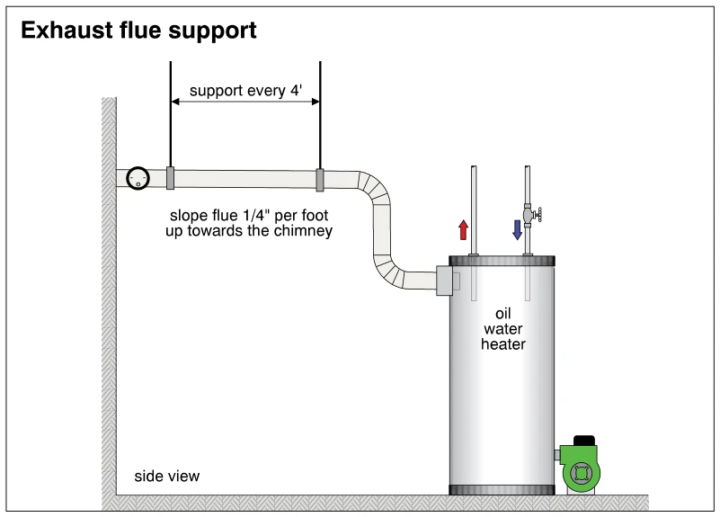 1590
1590Exhaust flue support
· p. 277
The side-view illustration shows an oil-fired water heater connected to a chimney by a metal exhaust flue. Elbows connect the heater's side flue outlet to an elevated run leading toward the chimney. Two overhead hangers support the flue, with an annotation specifying support every 4 feet. The flue is specified to slope upward toward the chimney at 1/4 inch per foot. Water piping extends above the tank, and an oil burner is mounted near its base.
 1591
1591Exhaust flue length
· p. 277
The side-view illustration shows an oil-fired water heater with a burner mounted near its base and an exhaust flue connected near its top. The flue runs toward the wall through two elbows, a vertical section, and a horizontal section. An annotation states that an elbow is equivalent to about 10 feet of straight flue, and a general-rule note gives a maximum flue length of 10 feet plus two elbows. Two water pipes extend above the tank, with red and blue arrows indicating outgoing hot water and incoming cold water; a shutoff valve is shown on the cold-water pipe.
Water Heaters ·Conventional Tank Type Water Heatersp. 278
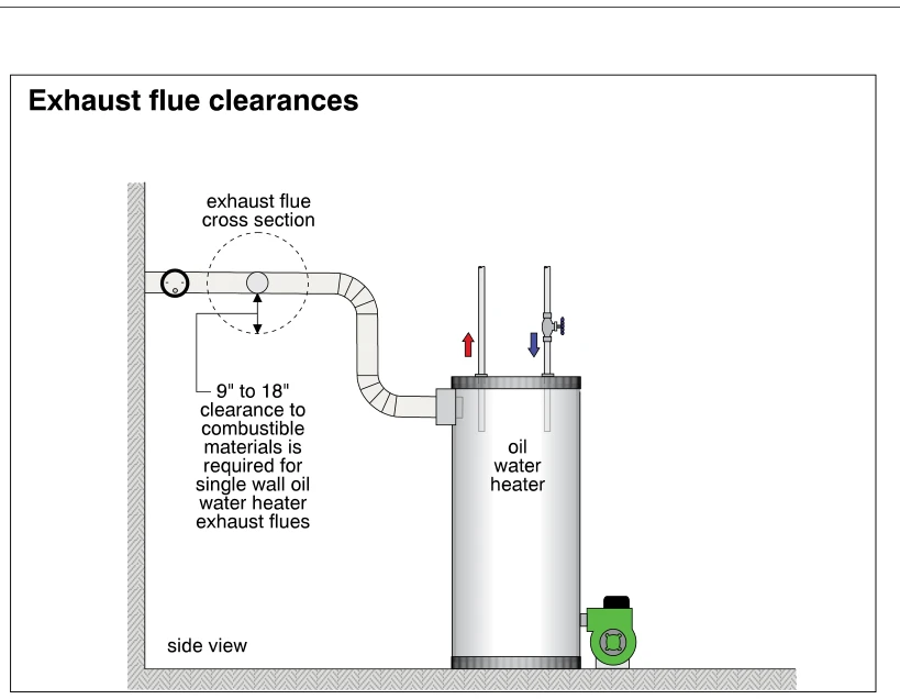 1592
1592Exhaust flue clearances
· p. 278
The side-view illustration shows an oil-fired tank water heater with a single-wall exhaust flue extending from its upper side toward a wall. Elbows connect the lower horizontal section to a vertical rise and an upper horizontal run. A circular cross-section detail and dimension arrows illustrate clearance around the flue, with an annotation specifying 9 to 18 inches of clearance to combustible materials. The heater also has a burner near its base and two top water connections, with red and blue arrows indicating outgoing hot water and incoming cold water.
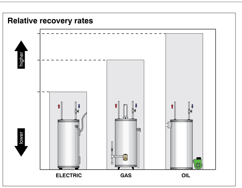 1593
1593Relative recovery rates
· p. 278
The illustration compares relative recovery rates for electric, gas, and oil conventional tank-type water heaters using three vertical bars. Electric has the lowest recovery rate, gas is intermediate, and oil has the highest. Each bar contains a drawing of the corresponding storage water heater, with red and blue arrows indicating hot-water outlet and cold-water inlet flow. The gas heater has a top-mounted vent and a lower gas control, while the oil heater has a burner mounted near its base. No numerical recovery rates or units are provided.
 1594
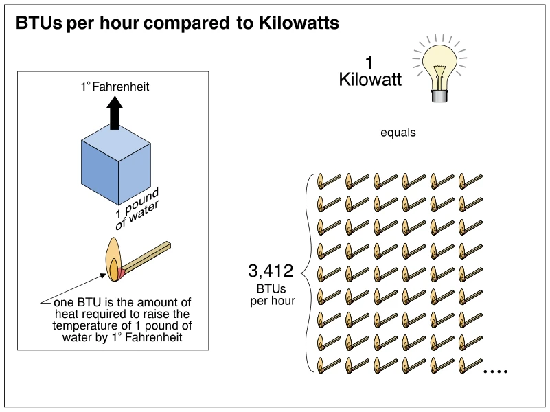
1594BTUs per hour compared to Kilowatts
· p. 278
The illustration explains the relationship between thermal energy and heating power using water, burning matches, and a light bulb as visual symbols. At left, a burning match beneath a cube representing one pound of water illustrates that one BTU raises its temperature by 1° Fahrenheit. At right, a light bulb labeled 1 Kilowatt is equated to 3,412 BTUs per hour, represented by an array of burning matches. This is a unit-conversion diagram relevant to water-heater ratings, not a depiction of a water-heater assembly or installation defect.
 1595
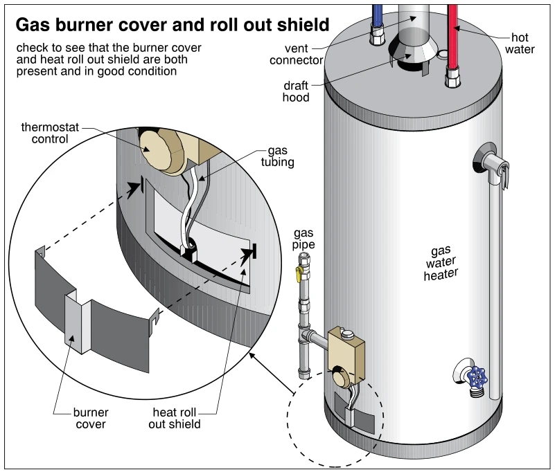
1595Gas burner cover and roll out shield
· p. 278
The illustration shows a conventional gas-fired tank water heater with a top-mounted draft hood and vent connector, hot-water outlet, gas supply pipe, and thermostat control. An enlarged detail of the lower burner access area shows the burner cover pulled away to reveal the heat roll out shield and gas tubing behind it. Dashed arrows indicate the cover's installed position over the access opening. The annotation instructs inspectors to verify that both the burner cover and heat roll out shield are present and in good condition; no specific defect is depicted.
 1596
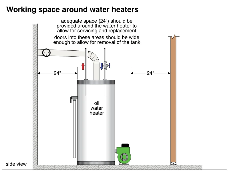
1596Working space around water heaters
· p. 278
The side-view illustration shows an oil-fired storage-tank water heater between enclosing walls. Dimension arrows indicate 24 inches of working clearance on either side of the equipment. Annotations call for adequate space for servicing and replacement and doors wide enough to remove the tank. The heater has top-mounted water piping, a vent connector leading toward the left wall, a side-mounted oil burner near the base, and a side valve with a discharge pipe extending downward.
 1597
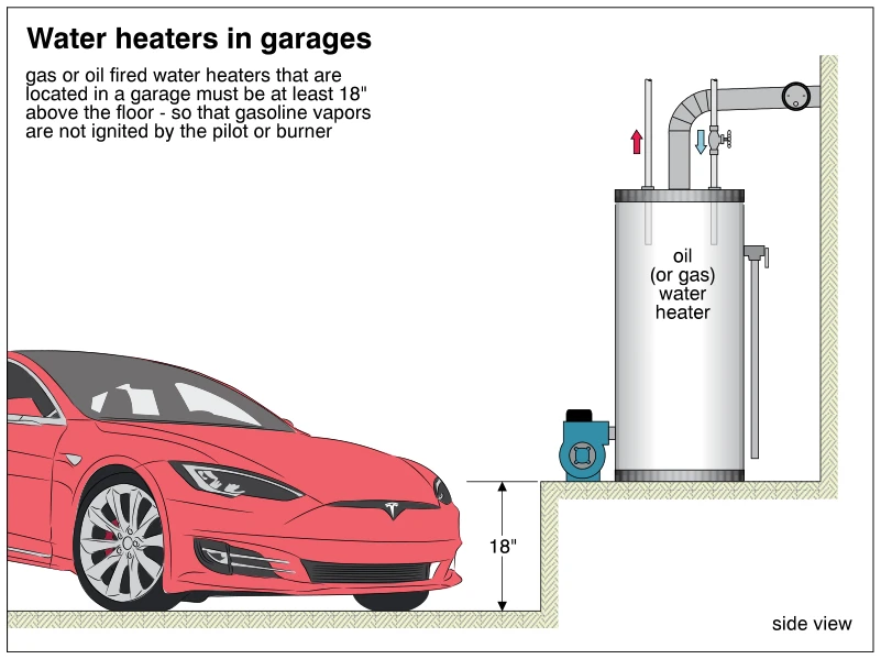
1597Water heaters in garages
· p. 278
The side-view illustration shows a fuel-fired tank water heater on a raised platform beside a vehicle in a garage. A dimension indicates that the platform is 18 inches above the garage floor. The heater has a burner assembly near its base, water piping at the top, an exhaust vent turning toward the wall, and a side-mounted valve with a discharge pipe extending downward. The annotation explains that elevation is intended to prevent gasoline vapors from being ignited by the pilot or burner.
 1598
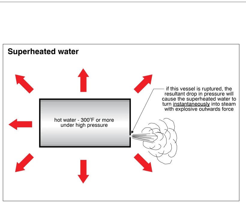
1598Superheated water
· p. 279
A schematic vessel contains water labeled as 300°F or more under high pressure. A rupture in its right side releases a plume of steam. The annotation explains that the pressure drop causes the superheated water to turn instantaneously into steam with explosive outward force. Large red arrows radiating away from the vessel illustrate the direction of that force.
 1599
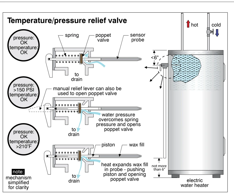
1599Temperature/pressure relief valve
· p. 279
The illustration shows a temperature/pressure relief valve installed near the top of an electric tank-type water heater, with a discharge pipe extending down to within 6 inches of the floor. Three simplified valve cross-sections show normal operation, relief under pressure exceeding 150 PSI, and relief under temperature exceeding 210°F. Under excess pressure, water overcomes the spring force and opens the poppet valve to the drain outlet. Under excess temperature, expanding wax in the sensor probe pushes a piston to open the valve; a manual relief lever can also open the poppet. The tank drawing shows hot and cold connections and a less-than-6-inch dimension locating the relief valve near the tank top.
 1600
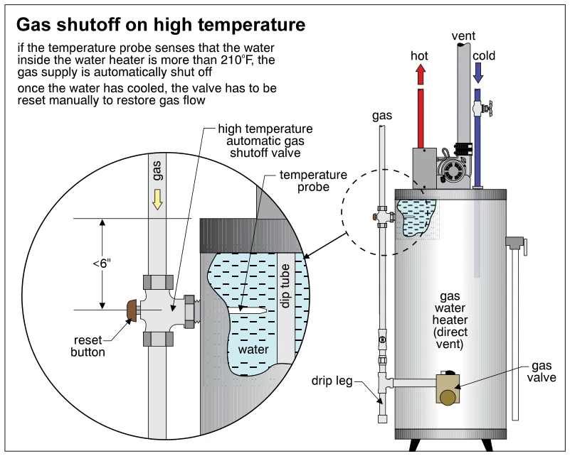
1600Gas shutoff on high temperature
· p. 279
The illustration shows a direct-vent gas storage water heater with hot and cold water connections, a vent, and an external gas supply line. An enlarged cutaway details a high-temperature automatic gas shutoff valve with a temperature probe extending into the tank near the dip tube. The annotation states that water temperatures above 210°F cause the valve to shut off the gas supply automatically, and manual resetting is required after the water cools. The detail marks a vertical distance of less than 6 inches between an upper reference line and the probe level. The main view also identifies the lower gas valve and a drip leg in the gas piping.
 1601
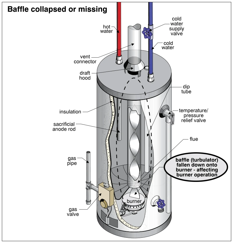
1601Baffle collapsed or missing
· p. 279
A cutaway view of a gas-fired tank-type water heater shows the central flue, burner, water connections, and internal tank components. A twisted flue baffle (turbulator) has fallen down onto the burner, with a callout identifying interference with burner operation. The flue leads upward through the tank to a draft hood and vent connector. The drawing also identifies the cold-water dip tube, sacrificial anode rod, tank insulation, gas valve and piping, and temperature/pressure relief valve.
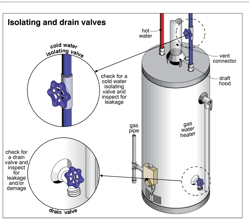 1602
1602Isolating and drain valves
· p. 280
The illustration shows a conventional gas-fired tank water heater with hot-water and cold-water connections at the top. An enlarged detail identifies the cold-water isolating valve and instructs the inspector to check for its presence and leakage. A second enlarged detail shows the threaded drain valve near the bottom of the tank, with instructions to check for leakage or damage. The heater also has a draft hood and vent connector, a gas supply pipe and control assembly, and a side-mounted relief valve with a discharge pipe extending toward the base. No actual leakage or damage is depicted.
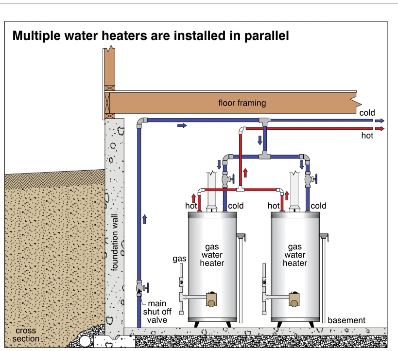 1603
1603Multiple water heaters are installed in parallel
· p. 280
A basement cross section shows two gas-fired storage-tank water heaters connected in parallel. The blue cold-water supply rises past a main shutoff valve and branches through a common manifold to the cold inlet of each heater, with an individual valve on each branch. Red piping joins the hot outlets of both tanks into a common hot-water distribution line. Arrows indicate cold water flowing into both heaters and hot water flowing out toward the shared outlet. Gas supply connections, short vent sections, and side-mounted discharge piping are also shown, alongside the foundation wall and beneath the floor framing.
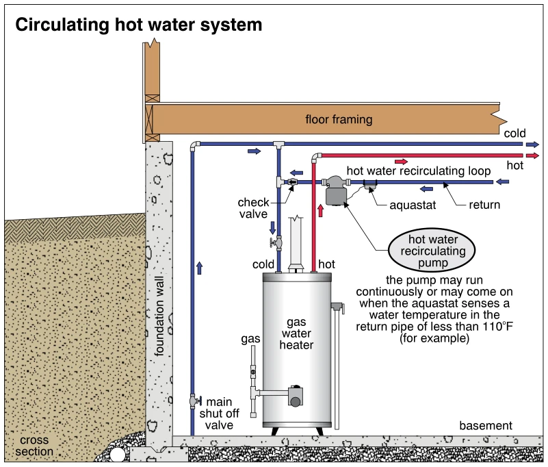 1604
1604Circulating hot water system
· p. 280
A basement cross section shows a gas-fired tank water heater connected to a domestic hot water recirculating system. Blue piping supplies cold water through a main shutoff valve and branches to the heater, while red piping carries hot water away from the tank. A separate return line directs water through an aquastat, recirculating pump, and check valve into the heater's cold-water supply connection. Directional arrows indicate flow through the supply and return piping. An annotation explains that the pump may run continuously or start when the aquastat senses return water below an example temperature of 110°F.
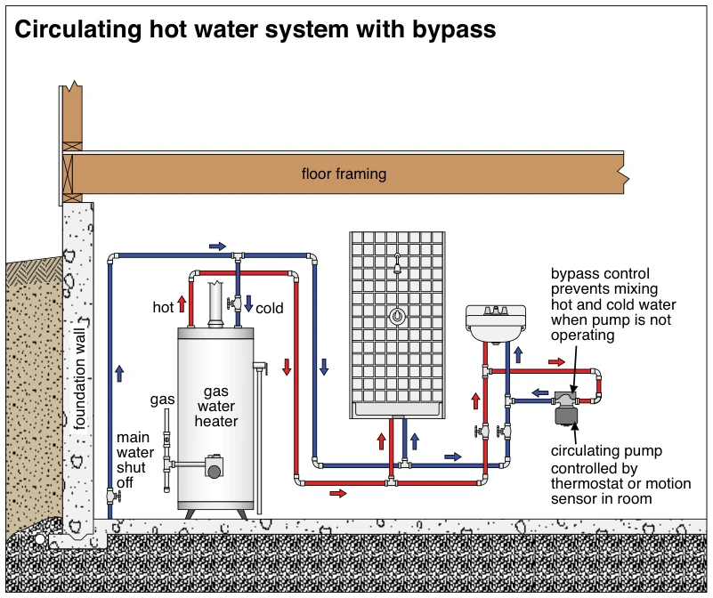 1604.5
Circulating hot water system with bypass
· p. 280
The schematic shows a gas-fired storage water heater supplying a shower and sink through red hot-water piping, with blue piping representing the cold-water supply. A circulating pump near the sink connects the hot and cold lines through a bypass, with arrows showing circulation from the hot line back into the cold line. The bypass control prevents hot and cold water from mixing when the pump is not operating. An annotation identifies thermostat or room motion-sensor control of the pump. The drawing also shows the main water shutoff, gas supply, floor framing, foundation wall, and floor slab.
Water Heaters ·High Efficiency Gas Water Heatersp. 281
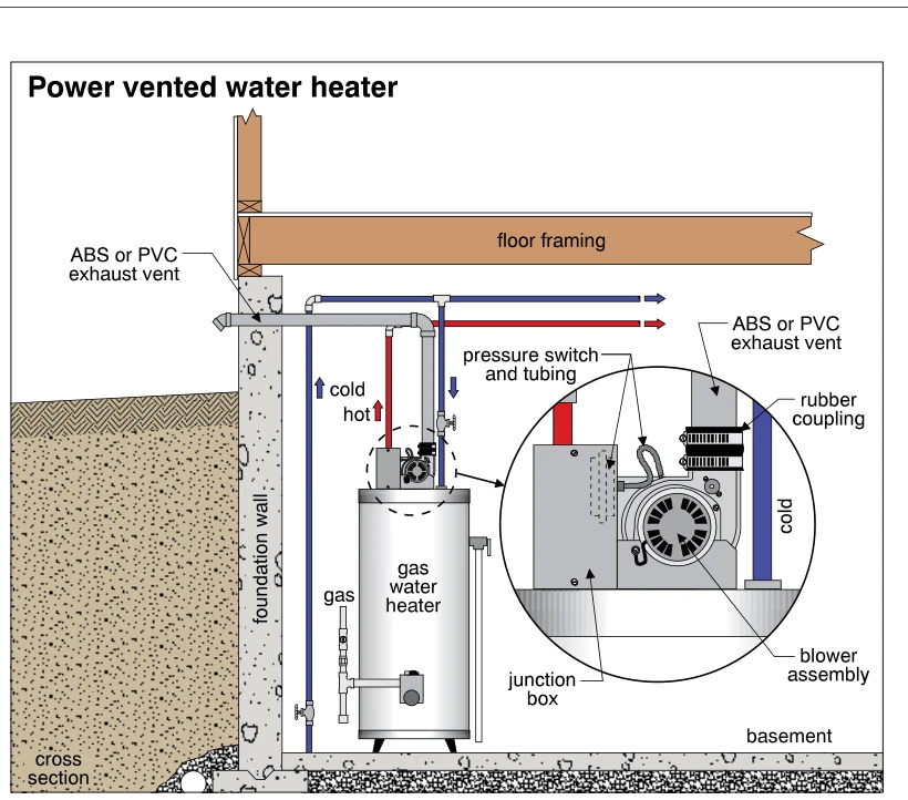 1605
1605Power vented water heater
· p. 281
The cross section shows a gas storage water heater in a basement beside a foundation wall. A blower mounted on top of the heater discharges through an ABS or PVC exhaust vent that rises and runs horizontally through the foundation wall to the exterior. Red and blue piping identifies the hot-water outlet and cold-water supply, and a gas line connects to the lower portion of the heater. An enlarged detail shows the blower assembly, junction box, pressure switch and tubing, and a clamped rubber coupling connecting the blower discharge to the exhaust vent. Floor framing, the basement slab, and exterior soil establish the installation context; no specific defect is identified.
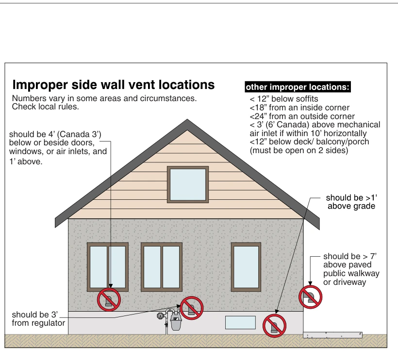 1606
1606Improper side wall vent locations
· p. 281
The illustration shows a house elevation with four sidewall vent terminations marked by red prohibition symbols to identify improper water-heater vent locations. The examples place vents beneath a window, near a gas regulator, close to grade, and low above a paved public walkway or driveway. Callouts specify separation distances from openings, the regulator, grade, and public paving. Additional annotations identify inadequate clearances from soffits, inside and outside corners, mechanical air inlets, and decks, balconies, or porches. A note cautions that the dimensions vary by area and circumstance and directs the reader to check local rules.
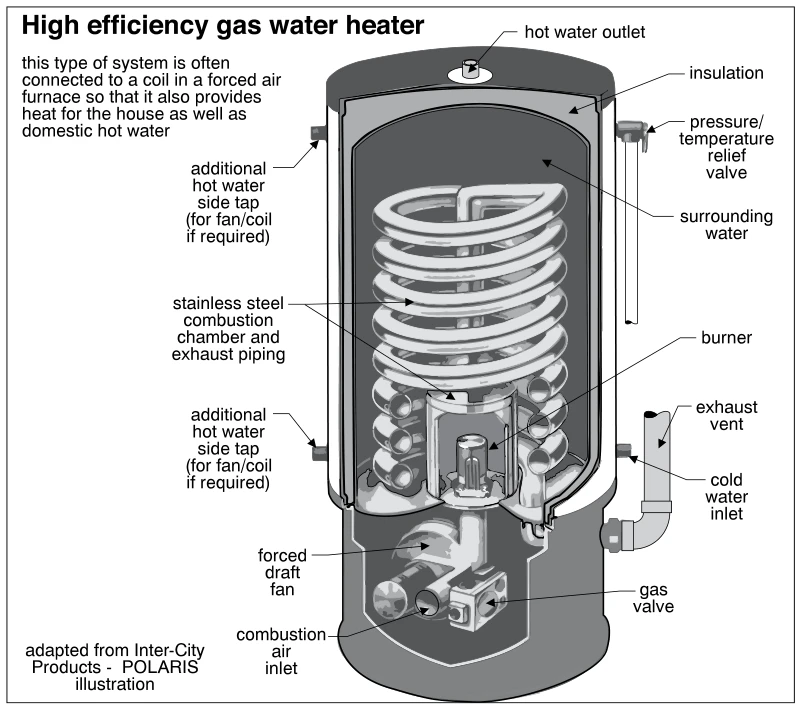 1607
1607High efficiency gas water heater
· p. 281
A cutaway depicts an insulated, high-efficiency gas storage water heater with a stainless steel combustion chamber and coiled exhaust piping surrounded by tank water. The burner is located low in the tank, with a forced draft fan, gas valve, and combustion air inlet in the compartment below. Connections include a top hot water outlet, a lower cold water inlet, a side exhaust vent, and a pressure/temperature relief valve with a downward discharge pipe. Two additional hot water side taps are identified for an optional fan/coil connection. An annotation explains that this type of heater is often connected to a coil in a forced air furnace to provide both space heating and domestic hot water.
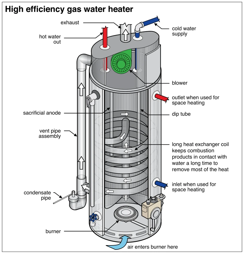 1607.5
High efficiency gas water heater
· p. 281
A cutaway depicts a high-efficiency gas storage water heater with a burner at the base and a long helical heat exchanger inside the tank. Arrows show combustion products traveling through the heat exchanger and into an external vent pipe assembly, with exhaust and a blower shown at the top. A condensate pipe connects near the bottom of the vent assembly. Top connections provide cold water supply through a dip tube and hot water discharge, while a sacrificial anode extends into the tank. Separate side inlet and outlet connections are identified for space-heating use, and an arrow marks combustion air entering beneath the burner.
Water Heaters ·Combination Systemsp. 282
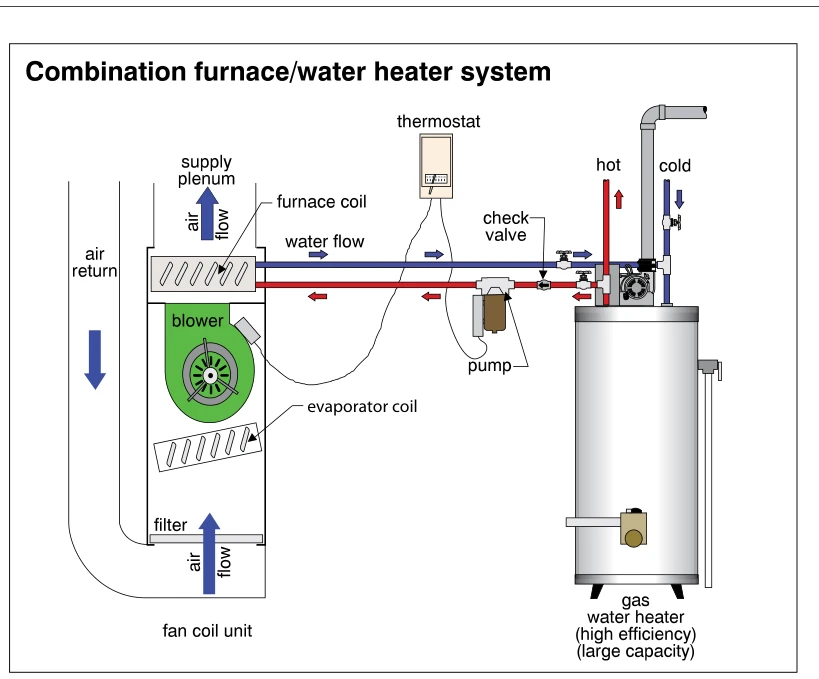 1608
1608Combination furnace/water heater system
· p. 282
The illustration shows a high-efficiency, large-capacity gas water heater connected to a fan coil unit for combined domestic water heating and space heating. A pump circulates hot water from the heater through the furnace coil, with arrows indicating supply and return water flow and a check valve identified in the piping. Return air travels down the return duct and then upward through a filter, past an evaporator coil and blower, and through the furnace coil into the supply plenum. A thermostat is shown with control wiring to the equipment. The water heater also has separate hot and cold domestic water connections and a vent pipe extending above it.
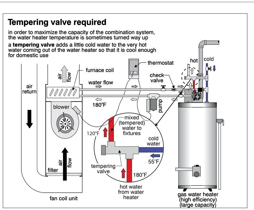 1609
1609Tempering valve required
· p. 282
The illustration shows a combination space-heating and domestic hot-water system using a high-efficiency, large-capacity gas water heater connected to a fan coil unit. A pump circulates water through the furnace coil, while a blower moves return air through a filter and upward across the coil. The piping includes a check valve, and a thermostat is shown wired to the system. An enlarged detail shows a tempering valve mixing 180°F water from the heater with 55°F cold water to supply fixtures with 120°F tempered water. The annotations explain that elevated water-heater temperatures may increase combination-system capacity, making tempering necessary for domestic use.
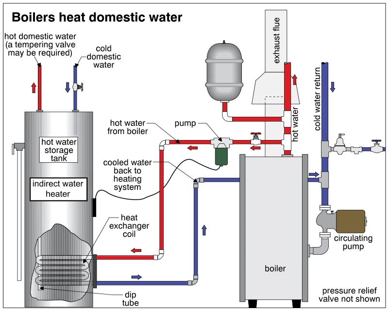 1610
1610Boilers heat domestic water
· p. 282
The illustration shows a boiler connected to an indirect domestic water heater with a storage tank and internal heat exchanger coil. Red piping and arrows indicate hot boiler water pumped through the coil, while blue piping returns cooled water to the heating system. A separate domestic cold-water inlet feeds the tank through a dip tube, and hot domestic water exits at the top, with a note that a tempering valve may be required. The boiler also has heating supply and return piping, a circulating pump, an expansion tank, and an exhaust flue. A cutaway exposes the coil and dip tube inside the storage tank, and an annotation states that the pressure relief valve is not shown.
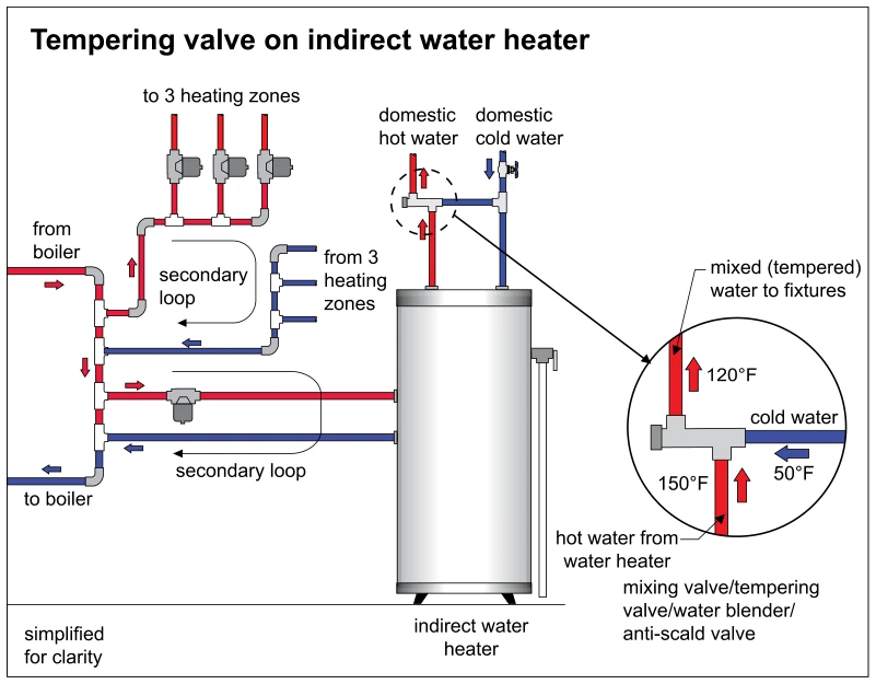 1610.1
Tempering valve on indirect water heater
· p. 282
The schematic depicts an indirect water heater connected to a boiler system with separate secondary loops for the water heater and three space-heating zones. Red and blue piping and arrows indicate supply and return flow paths. A tempering valve connects the domestic hot-water outlet to the domestic cold-water supply before water flows to fixtures. An enlarged detail shows 150°F water from the heater mixing with 50°F cold water to deliver tempered water at 120°F. The valve is also identified as a mixing valve, water blender, and anti-scald valve.
 1611
1611Tankless coil
· p. 282
The illustration shows a tankless domestic-water heating coil installed near the top of a boiler, where the boiler water is hottest. Domestic cold water enters the lower connection, passes through the finned copper coil, and leaves through the domestic hot-water outlet, remaining separate from the boiler water. A hot-water supply riser and a cold-water return with a circulating pump form the boiler heating circuit, with an expansion tank connected to the supply side. Arrows indicate flow directions in both circuits. A note states that the pressure relief valve is not shown; no improper installation is depicted.
 1612
1612Side arm heater
· p. 282
The illustration shows a side arm domestic water heater mounted outside a hot-water boiler. Hot boiler water passes through the external heat exchanger around a coil and returns to the boiler return piping. Domestic cold water enters the coil at the bottom, is heated by the boiler water, and exits as domestic hot water at the top. Red and blue piping and arrows distinguish the hot supply and cooler return flows. The assembly also shows a circulating pump, an expansion tank, an exhaust flue, and piping valves; a note states that the pressure relief valve is not shown.
Water Heaters ·Tankless Coilsp. 283
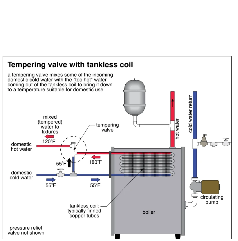 1613
1613Tempering valve with tankless coil
· p. 283
The schematic shows a boiler with an internal tankless coil that heats domestic water separately from the boiler's circulating heating water. Domestic cold water enters the coil at 55°F and exits at 180°F. A tempering valve blends cold supply water with the hot coil discharge to deliver mixed water to fixtures at 120°F. Red and blue piping and directional arrows distinguish hot discharge, cold supply, and mixed-water flow. The boiler circuit includes hot-water supply and cold-water return piping, a circulating pump, and an expansion tank; an annotation states that the pressure relief valve is not shown.
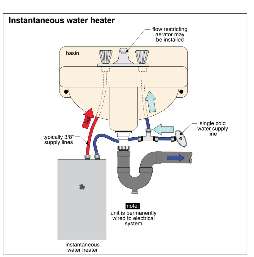 1614
1614Instantaneous water heater
· p. 283
The illustration shows an instantaneous point-of-use water heater installed beneath a basin. A single cold-water supply line branches to feed both the faucet's cold side and the heater inlet, while a separate hot-water line connects the heater outlet to the faucet's hot side. The supply lines are labeled as typically 3/8 inch, and an annotation indicates that a flow-restricting aerator may be installed at the faucet outlet. A note specifies that the heater is permanently wired to the electrical system. The basin drain and P-trap are also shown, with an arrow indicating drainage flow.
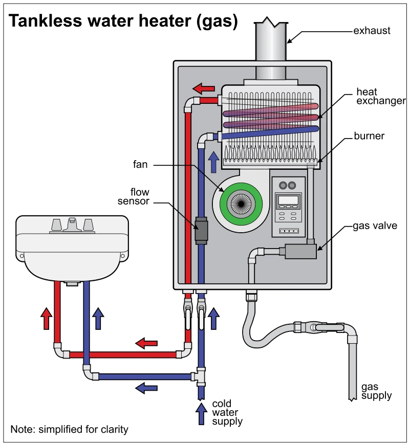 1614.2
Tankless water heater (gas)
· p. 283
The illustration shows a gas-fired tankless water heater supplying a sink, with the cabinet opened to reveal its internal components. Blue piping carries cold water to both the sink and the heater, passing through a flow sensor before entering the heat exchanger. A burner beneath the heat exchanger heats the water, and red piping carries the heated water to the sink; arrows indicate flow direction. A separate gas supply connects to the internal gas valve, while a fan is shown below the burner and an exhaust connection exits the top of the cabinet. Shutoff valves are shown on the water connections and gas supply, and no defects are indicated.
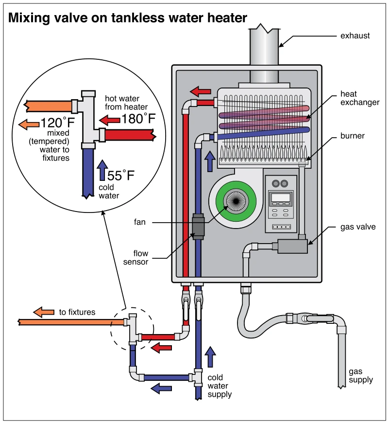 1614.4
Mixing valve on tankless water heater
· p. 283
The illustration shows a gas-fired tankless water heater with an external mixing valve on its hot-water outlet. Cold supply water branches to both the heater inlet and the mixing valve, where it blends with hot water before flowing to fixtures. An enlarged detail shows 180°F water from the heater mixing with 55°F cold water to deliver 120°F tempered water. The heater cutaway identifies the heat exchanger, burner, fan, flow sensor, gas valve, and exhaust. Colored piping and arrows distinguish cold, hot, and tempered water and indicate flow direction.
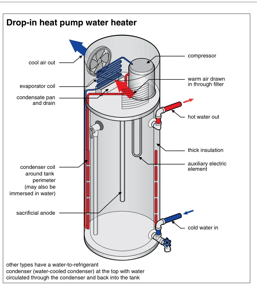 1614.6
Drop-in heat pump water heater
· p. 284
A cutaway shows a cylindrical heat pump water heater with a compressor, evaporator coil, fan, air filter, and condensate pan and drain mounted above the storage tank. Arrows indicate warm air entering through the filter and cool air leaving through the fan opening. A condenser coil runs around the tank perimeter, while thick insulation surrounds the tank; an auxiliary electric heating element and sacrificial anode are shown inside. Hot water exits near the top and cold water enters near the bottom through color-coded connections. An annotation describes an alternative top-mounted water-cooled condenser arrangement that circulates tank water through the condenser and back into the tank.
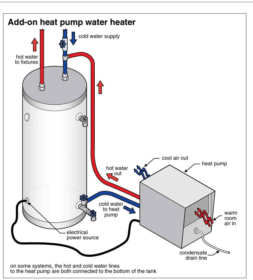 1614.8
Add-on heat pump water heater
· p. 284
The illustration shows a storage water heater connected to a separate add-on heat pump by water lines. Blue arrows indicate cold water flowing from the bottom of the tank to the heat pump, while red arrows show heated water returning to a connection at the tank's cold-water inlet piping. Separate top connections supply cold water to the tank and deliver hot water to fixtures. The heat pump takes in warm room air, discharges cool air, and has a condensate drain line and an electrical power connection. A note explains that some systems connect both heat-pump water lines to the bottom of the tank; no defect is depicted.
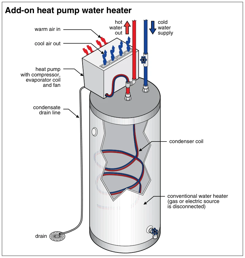 1614.9
Add-on heat pump water heater
· p. 284
The illustration shows an add-on heat pump mounted above a conventional storage water heater whose gas or electric energy source is disconnected. The heat pump contains a compressor, evaporator coil and fan, with arrows indicating warm air entering and cool air leaving. A cutaway in the tank reveals the condenser coil connected to the heat pump. Hot water exits and cold water enters through separate connections at the top of the tank. A condensate drain line runs from the heat pump down to a floor drain.
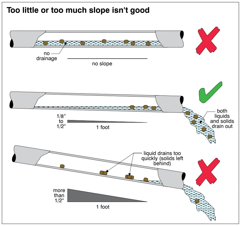 1615
1615Too little or too much slope isn't good
· p. 284
Three cutaway drain pipes compare the effects of different slopes on liquid and solid waste transport. The upper pipe has no slope, retains liquid and solids, and is marked with a red X. The middle pipe slopes downward 1/8 inch to 1/2 inch per foot and is marked with a green check, showing liquids and solids draining out together. The lower pipe slopes more than 1/2 inch per foot and is marked with a red X, showing liquid draining too quickly while solids remain behind.
Drain, Waste And Vent Plumbing ·Introductionp. 285
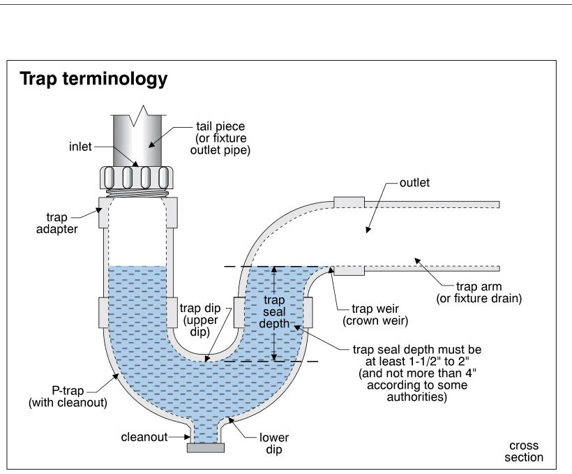 1616
1616Trap terminology
· p. 285
A cross section of a P-trap identifies the terminology for its inlet, bends, outlet, and retained water seal. A vertical fixture tail piece connects through a trap adapter to the inlet, and the outlet extends horizontally as the trap arm or fixture drain. Blue shading shows water retained in the curved trap up to the trap weir, with a vertical dimension marking the trap seal depth down to the upper dip. A note specifies a minimum seal depth of 1-1/2 to 2 inches and a maximum of 4 inches according to some authorities. A cleanout is shown at the bottom of the lower dip.
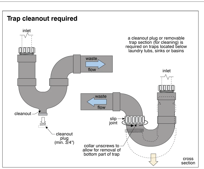 1617
1617Trap cleanout required
· p. 285
The illustration shows two drain trap arrangements that provide access for cleaning beneath laundry tubs, sinks, or basins. The left trap has a cleanout opening at its lowest point and a removable plug labeled with a minimum size of 3/4 inch. The right cross-sectional view shows a slip-joint collar that unscrews to permit removal of the bottom part of the trap, with dashed outlines indicating the removable section. Arrows identify wastewater flow from each inlet through the trap toward its horizontal outlet. Both arrangements illustrate ways to meet the stated requirement for trap cleaning access.
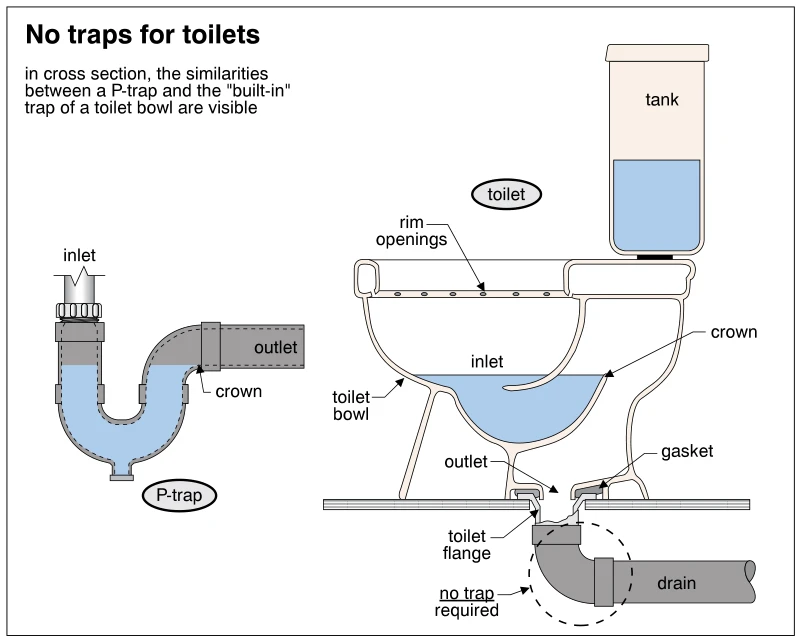 1618
1618No traps for toilets
· p. 285
The illustration compares a separate P-trap in cross section with the built-in trapway of a toilet. Blue shading shows retained water in both assemblies, and labels identify their inlets, crowns, and outlets. The toilet section also shows the tank, rim openings, bowl, and outlet connection through a gasket to the toilet flange at floor level. Below the flange, an elbow connects to the drain; a dashed circle and annotation emphasize that no additional trap is required.
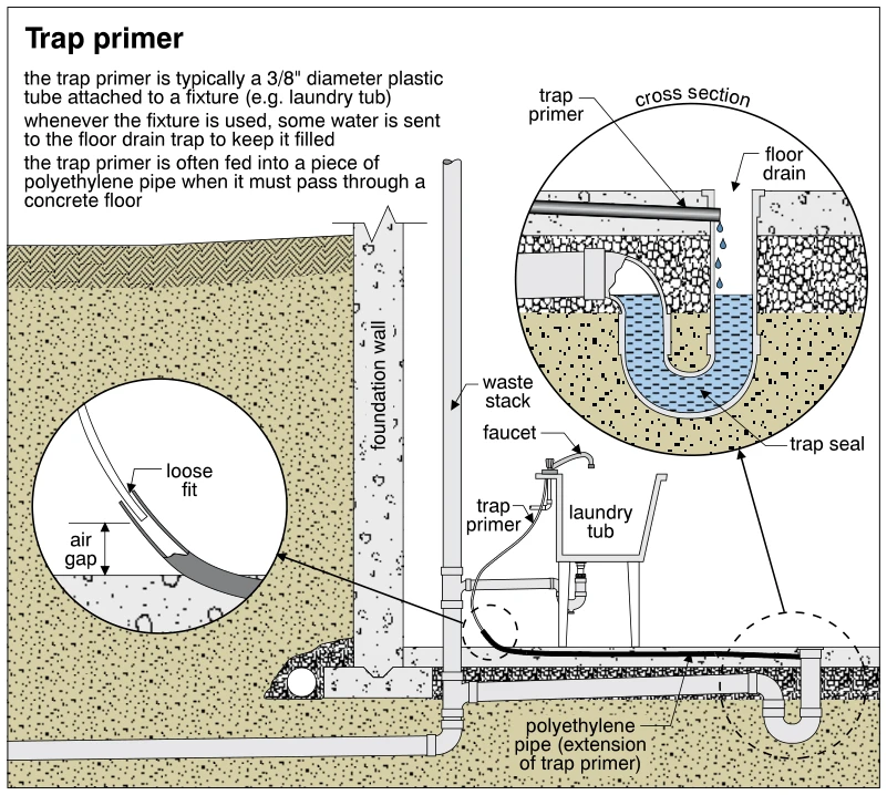 1619
1619Trap primer
· p. 285
The illustration shows a laundry-tub faucet supplying a trap-primer tube that delivers water to a floor-drain trap beneath a concrete floor. The primer tube feeds into a polyethylene pipe extension, with an enlarged detail identifying a loose fit and air gap at the connection. A second enlarged cross section shows water dripping from the primer into the floor drain and maintaining the trap seal. The surrounding assembly includes the foundation wall, waste stack, laundry-tub drain, and below-floor drainage piping. The annotations explain that fixture use replenishes the floor-drain trap.
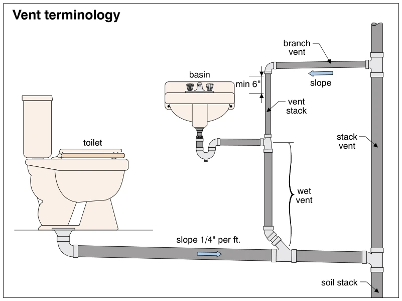 1620
1620Vent terminology
· p. 285
The diagram shows a toilet and basin connected to a common drainage and vent piping assembly. The basin discharges through a trap into a vertical pipe whose section below the basin connection is labeled as a wet vent and connects to the toilet drain. Above the basin connection, the pipe is labeled as a vent stack and rises to a branch vent connected to the main stack. The branch vent is shown at least 6 inches above the basin rim, with a slope arrow pointing back toward the basin-side vent piping. The toilet drain slopes toward the soil stack at 1/4 inch per foot; the main vertical pipe above the drainage connection is labeled as the stack vent.
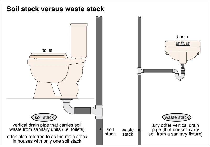 1621
1621Soil stack versus waste stack
· p. 285
The illustration compares a soil stack serving a toilet with a waste stack serving a basin. On the left, the toilet outlet passes through the floor and connects by an elbow and horizontal branch to a vertical soil stack. On the right, the basin drains through a P-trap and horizontal branch into a vertical waste stack. The annotations distinguish a soil stack, which carries toilet waste, from a waste stack, which does not carry soil from a sanitary fixture. The soil stack is also identified as commonly called the main stack in houses with only one soil stack.
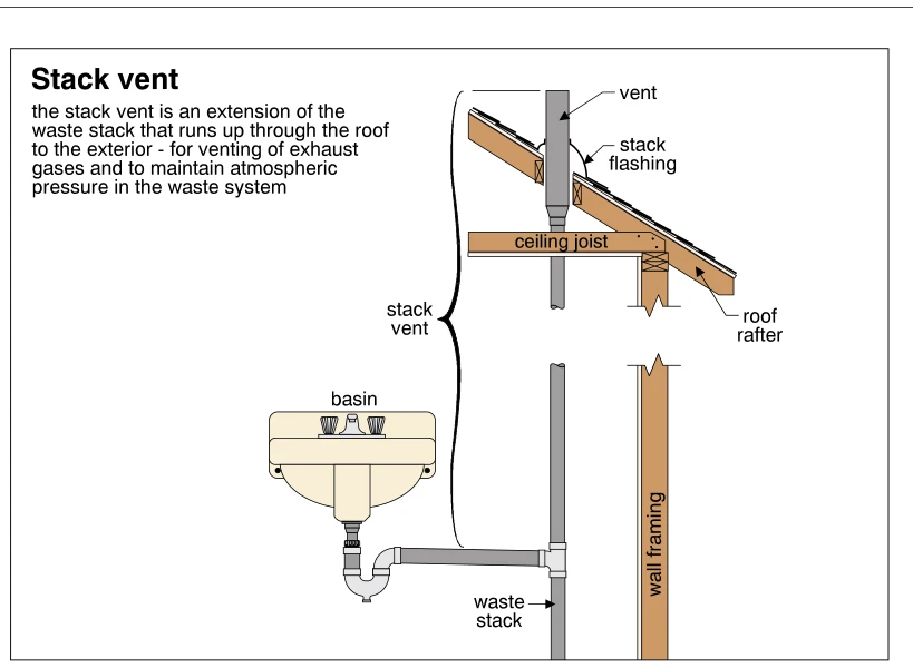 1622
1622Stack vent
· p. 286
The illustration shows a basin connected through a trap and horizontal drain to a vertical waste stack. Above the basin drain connection, the stack continues upward as a stack vent and terminates outdoors through a sloped roof. Stack flashing surrounds the roof penetration, with a ceiling joist, roof rafter, and wall framing shown for context. The annotation explains that the stack vent releases exhaust gases and maintains atmospheric pressure in the waste system.
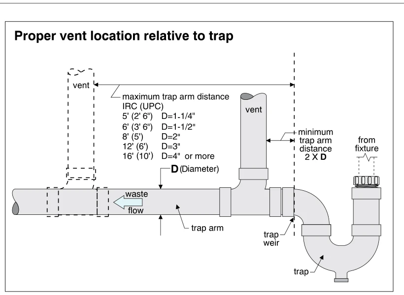 1623
1623Proper vent location relative to trap
· p. 286
The diagram shows a fixture drain entering a P-trap, with the trap arm carrying waste to the left and a vent rising from the drain downstream of the trap. The trap weir and pipe diameter D are identified as references for vent placement. A dimension indicates a minimum trap arm distance of twice the pipe diameter between the trap weir and vent. A dashed alternative vent location illustrates the maximum trap arm distance, with a table giving IRC and parenthetical UPC limits for several pipe diameters.
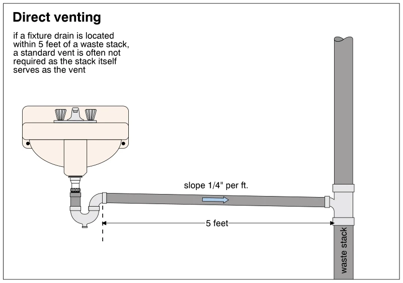 1624
1624Direct venting
· p. 286
A lavatory sink drains through a P-trap and a sloping horizontal fixture drain into a vertical waste stack. An arrow shows drainage flowing toward the stack, and the drain is labeled with a slope of 1/4 inch per foot. A dimension marks 5 feet between the trap outlet area and the stack. The annotation explains that a fixture drain within this distance often does not require a separate vent because the stack itself serves as the vent.
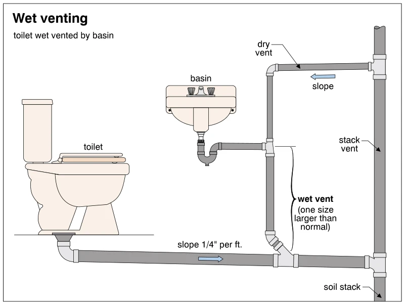 1625
1625Wet Venting
· p. 286
The illustration shows a toilet wet vented through a basin drain connection. The basin discharges through a trap into a vertical pipe that joins the toilet's horizontal drain upstream of the soil stack. The shared vertical section is labeled as a wet vent and specified to be one size larger than normal. Above the basin connection, a dry vent rises and turns toward the stack vent, with its horizontal section sloped back toward the basin branch. The toilet drain is labeled with a slope of 1/4 inch per foot toward the soil stack.
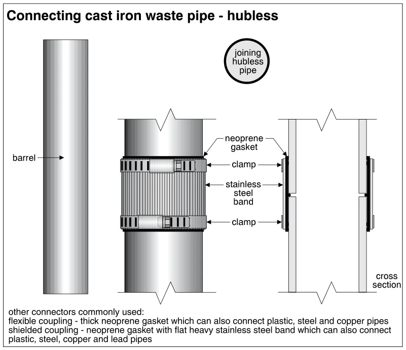 1626
1626Connecting cast iron waste pipe - hubless
· p. 286
The illustration shows a plain-ended cast iron waste pipe barrel and a hubless joint in exterior and cross-sectional views. Two pipe ends are joined by a neoprene gasket surrounded by a stainless steel band, secured with clamps at the top and bottom. The cross section shows the gasket wrapping the pipe ends and separating them at the joint. Notes identify flexible and shielded couplings as other commonly used connectors and list additional pipe materials they can connect.
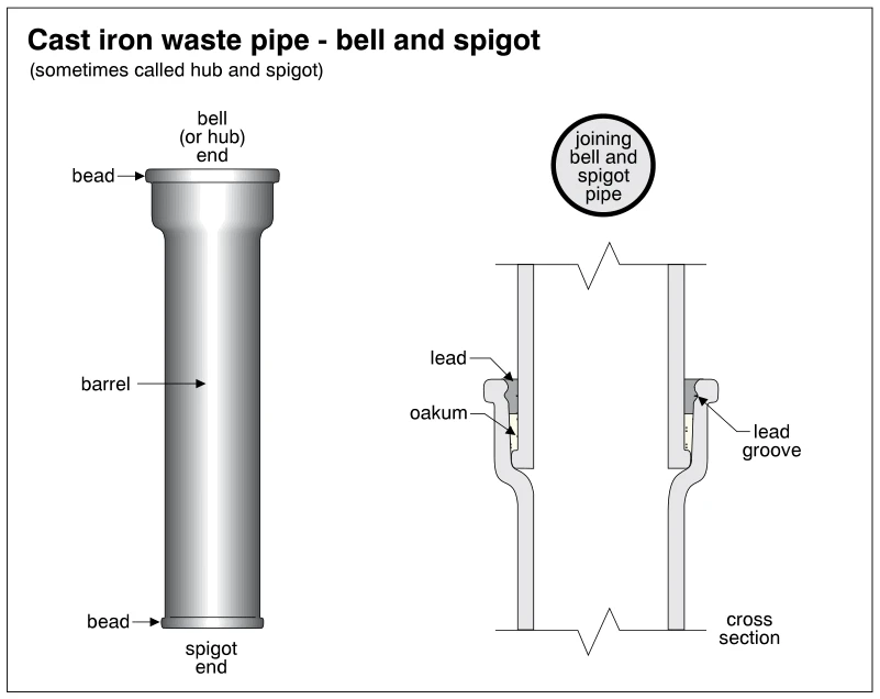 1627
1627Cast iron waste pipe - bell and spigot
· p. 286
The illustration shows a cast iron waste pipe with an enlarged bell, or hub, at one end and a spigot at the other. The exterior view identifies the barrel and beads at both ends. A separate cross section shows a spigot inserted into the bell of another pipe. Oakum fills the lower portion of the space between the pipes, with lead above it and a lead groove identified near the hub opening. No defects are depicted.
Drain, Waste And Vent Plumbing ·Drain Piping Materials and Problemsp. 287
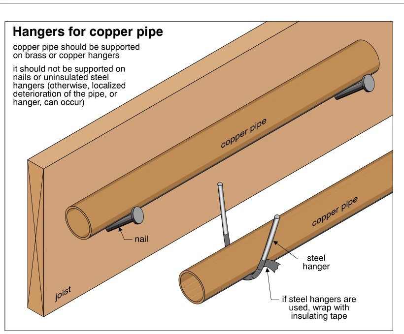 1628
1628Hangers for copper pipe
· p. 287
The illustration shows copper piping beside a wood joist, with one pipe improperly supported on nails driven into the joist. A separate detail shows a steel hanger supporting copper pipe, with insulating tape at the contact area. The annotations specify brass or copper hangers as suitable supports for copper piping. They warn that nails or uninsulated steel hangers can cause localized deterioration of the pipe or hanger, and instruct that steel hangers be wrapped with insulating tape.
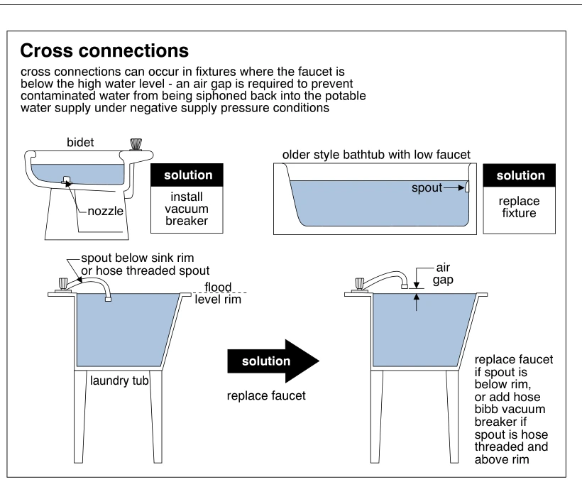 1629
1629Cross connections
· p. 287
The illustration shows cross-connection hazards at a bidet, an old-style bathtub with a low faucet, and a laundry tub. The bidet nozzle and bathtub spout are below the illustrated water levels; the indicated remedies are installing a vacuum breaker and replacing the fixture, respectively. A laundry tub with a spout below its flood-level rim is compared with a tub having a raised spout and an air gap above the rim. The annotations recommend replacing a faucet whose spout is below the rim, or adding a hose bibb vacuum breaker to a hose-threaded spout above the rim. These measures address the risk of contaminated fixture water being siphoned into the potable supply under negative supply pressure.
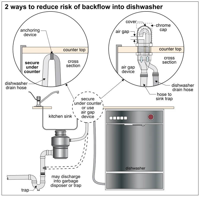 1630
16302 ways to reduce risk of backflow into dishwasher
· p. 287
The illustration shows two ways to reduce the risk of backflow into a dishwasher connected to a kitchen sink drainage system. One enlarged cross section shows the dishwasher drain hose looped high and secured beneath the countertop with an anchoring device. The other shows a countertop-mounted air gap device with a chrome cap, a dishwasher hose connection, and a separate hose leading toward the sink trap. The main view shows the dishwasher beside a kitchen sink with a garbage disposer and trap, with solid and dashed piping indicating alternative discharge connections into the disposer or trap.
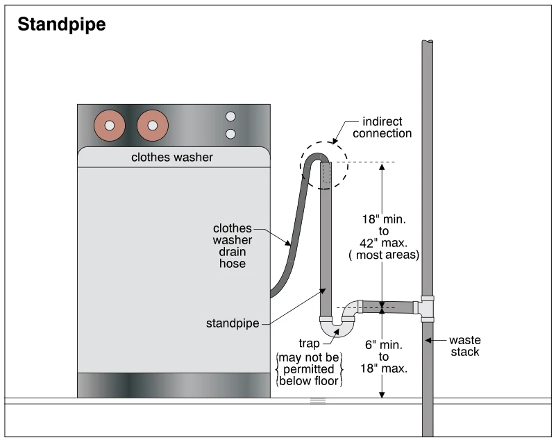 1631
1631Standpipe
· p. 287
The illustration shows a clothes washer draining through a flexible hose into an open standpipe with an indirect connection. The standpipe descends into a trap above the floor, and a horizontal trap arm connects to a vertical waste stack. A dimension indicates a standpipe height of 18 inches minimum to 42 inches maximum above the trap-arm level in most areas. Another dimension places the trap-arm level 6 inches minimum to 18 inches maximum above the floor. A note states that the trap may not be permitted below the floor.
Drain, Waste And Vent Plumbing ·Trapsp. 288
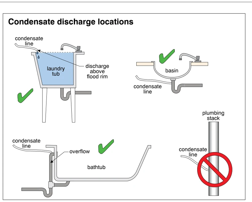 1632
1632Condensate discharge locations
· p. 288
The illustration compares condensate discharge arrangements at a laundry tub, basin, bathtub, and plumbing stack. Green check marks identify discharge above the laundry tub's flood rim, connection to the basin tailpiece upstream of its trap, and connection to the bathtub overflow upstream of its trap as acceptable arrangements. Each fixture is shown with a drain trap. A red prohibition symbol identifies a condensate line connected directly to a plumbing stack as an unacceptable arrangement.
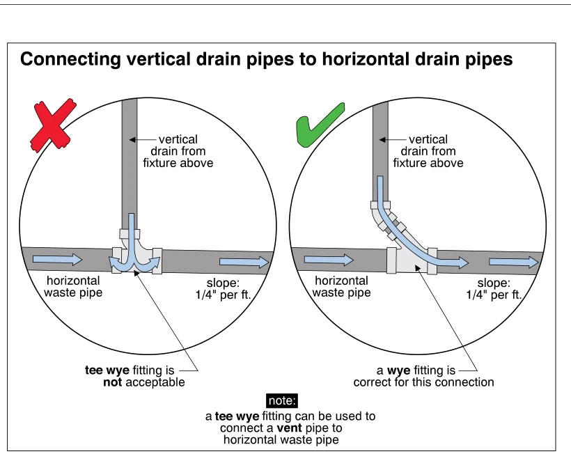 1633
1633Connecting vertical drain pipes to horizontal drain pipes
· p. 288
Two circular diagrams compare connections from a vertical fixture drain to a horizontal waste pipe. The left diagram, marked with a red X, shows an unacceptable tee wye fitting, with flow arrows splitting in opposite directions at the junction. The right diagram, marked with a green check, shows a bend and wye fitting directing the vertical discharge downstream into the horizontal pipe. Both horizontal waste pipes are labeled with a slope of 1/4 inch per foot. A note distinguishes drainage from venting by stating that a tee wye fitting can connect a vent pipe to a horizontal waste pipe.
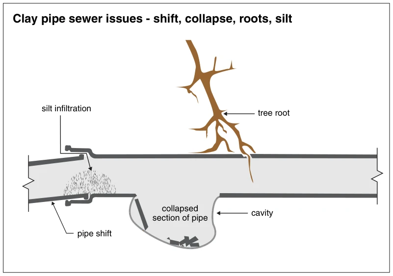 1633.6
Clay pipe sewer issues - shift, collapse, roots, silt
· p. 288
The illustration shows a longitudinal section through a clay sewer pipe with several failure conditions. At the left, a shifted pipe section is misaligned at a joint, where silt is entering and accumulating inside the pipe. In the center, part of the pipe bottom has collapsed into a cavity, with broken fragments lying below the original pipe invert. A tree root penetrates the top of the pipe farther to the right.
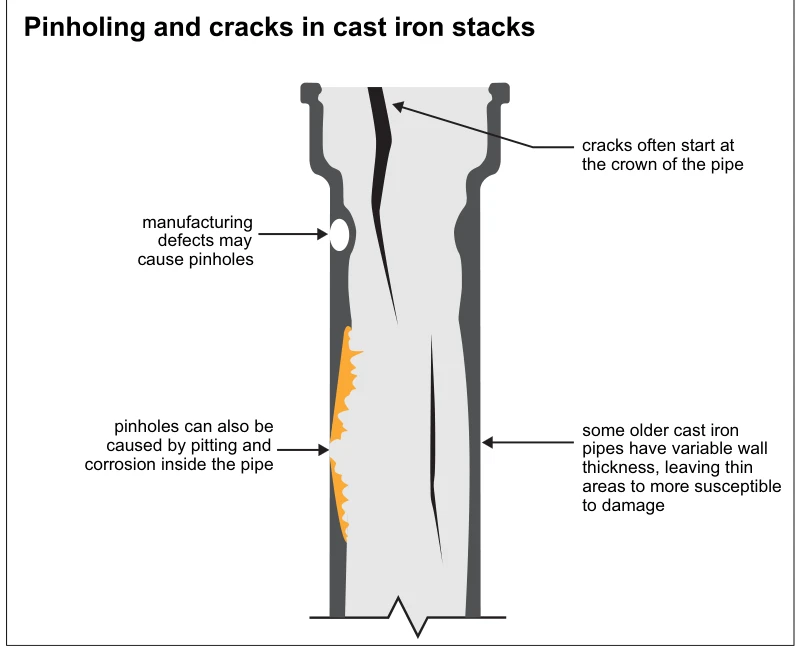 1633.3
Pinholing and cracks in cast iron stacks
· p. 288
The illustration shows a cutaway of a cast iron drain stack with pinholes, longitudinal cracks, and uneven pipe wall thickness. One pinhole is identified as a possible manufacturing defect, while another occurs at an area of internal pitting and corrosion. A callout notes that cracks often start at the crown of the pipe. The variable wall thickness of some older cast iron pipes leaves thin areas more susceptible to damage.
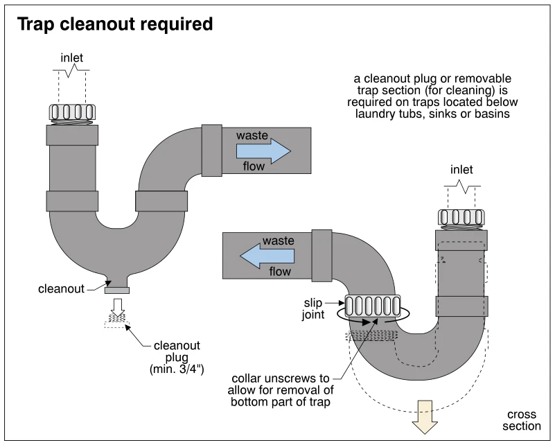 1634
1634Trap cleanout required
· p. 288
The illustration shows two plumbing trap arrangements that provide access for cleaning beneath laundry tubs, sinks or basins. The left trap has a cleanout opening at its lowest point and a removable plug labeled as a minimum of 3/4 inch. The right cross-sectional view shows a slip-joint collar that unscrews to permit removal of the bottom trap section, with dashed outlines and a downward arrow illustrating removal. Arrows indicate wastewater flow from each vertical inlet through the curved trap to a horizontal outlet.
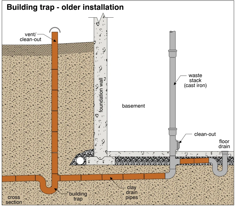 1635
1635Building trap - older installation
· p. 288
This cross section depicts an older building drainage installation with clay drain pipes below the basement floor and outside the foundation wall. A cast-iron waste stack has an accessible clean-out above the floor and connects to the buried drain through a curved fitting. A trapped floor drain also connects to the drainage piping beneath the slab. Outside the foundation, a building trap forms a low U-shaped bend in the drain, with a vertical vent/clean-out riser extending above grade. No specific failure or defect is indicated.
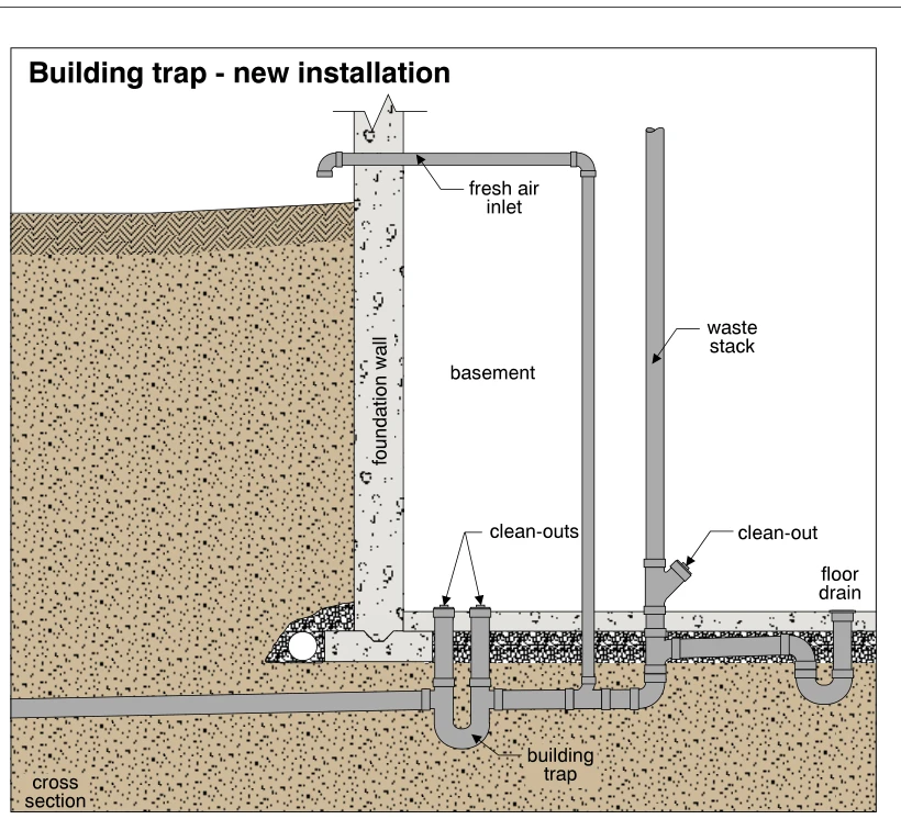 1636
1636Building trap - new installation
· p. 289
The cross section shows a basement drainage system with a building trap installed below the floor near the foundation wall. Two capped clean-out risers provide access to the building trap, and the drain continues underground to the exterior. A fresh air inlet connects on the building side of the trap, rises inside the basement, and passes through the foundation wall to a downturned exterior opening above grade. A waste stack with an angled clean-out and a separately trapped floor drain connect to the drainage piping upstream of the building trap.
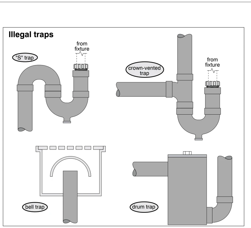 1637
1637Illegal traps
· p. 289
The illustration presents four plumbing trap configurations identified as illegal: an S trap, a crown-vented trap, a bell trap, and a drum trap. The S trap connects a fixture inlet through a U-shaped bend and an inverted bend to a downward discharge pipe. The crown-vented trap has a fixture inlet and a U-shaped bend connected directly to a vertical riser with a horizontal branch. The bell trap is shown in section beneath a grate, with a dome-shaped bell covering the top of a central outlet pipe. The drum trap has a large chamber with a top access cover, a horizontal side connection, and a lower side connection that turns upward.
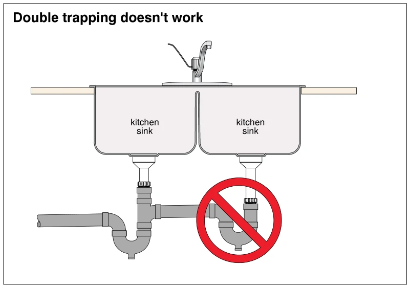 1638
1638Double trapping doesn't work
· p. 289
The illustration shows a double-bowl kitchen sink with interconnected drain piping below the basins. The right basin drains through a trap before joining the left basin's vertical drain connection. The combined discharge then passes through another trap before entering the horizontal waste pipe to the left. A red prohibition symbol over the right-hand trap identifies this double-trapping arrangement as improper.
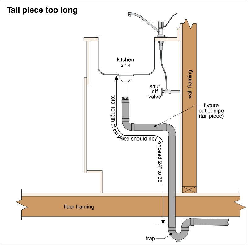 1639
1639Tail piece too long
· p. 289
A sectional drawing shows a kitchen sink with its fixture outlet pipe extending down, offsetting horizontally, and then dropping through the floor to a trap below the floor framing. The faucet supply line and shutoff valve are shown beside the sink, adjacent to the wall framing. A dimension arrow follows the long tailpiece route from the sink outlet to the trap, with an annotation stating that its total length should not exceed 24 to 36 inches. The illustration identifies this tailpiece arrangement as too long.
Drain, Waste And Vent Plumbing ·Floor Drainsp. 290
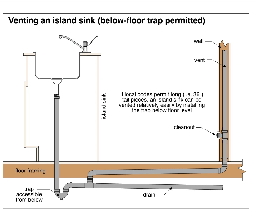 1640
1640Venting an island sink (below-floor trap permitted)
· p. 290
The illustration shows an island sink with a long vertical tailpiece extending through the floor to a trap accessible from below. The trap outlet connects to a horizontal drain beneath the floor. A vent branch rises from the drain downstream of the trap, runs horizontally at the floor framing, and turns upward inside an adjacent wall. A cleanout is shown near the base of the vertical wall vent. The annotation identifies this arrangement as an option where local codes permit long tailpieces, such as 36 inches, and a below-floor trap.
 1641
1641Loop vent or circuit vent for an island sink
· p. 290
The illustration shows an island sink with a tailpiece and P-trap located above the floor inside the cabinet. A loop vent rises beside the sink to just below the countertop, then returns downward through the floor to the drain piping. A foot vent branches from the return leg and runs through the floor framing to a vertical vent in a nearby wall. Cleanouts are shown at the below-floor drain connection and on the wall vent. The annotation explains that a loop or circuit vent arrangement is needed when the allowable tailpiece length does not permit the trap to be located below the floor.
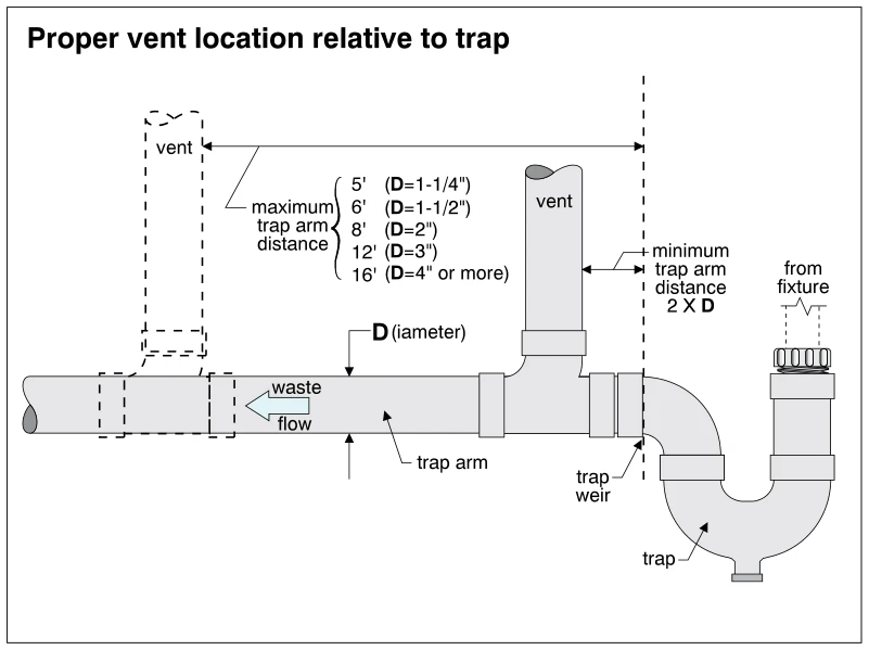 1642
1642Proper vent location relative to trap
· p. 290
The illustration shows a fixture drain entering a U-shaped trap, with a horizontal trap arm carrying waste to the left and a vent rising from the arm. The trap weir is marked as the reference point for vent-location measurements. The minimum trap arm distance is labeled as twice the pipe diameter, D. A dashed alternative vent location illustrates the maximum trap arm distance, with listed limits ranging from 5 feet for 1-1/4-inch pipe to 16 feet for pipe 4 inches or larger.
 1643
1643Trap terminology
· p. 290
The illustration shows a cross section of a P-trap with a bottom cleanout, connected to a vertical fixture tail piece through a trap adapter. The curved outlet leads into a horizontal trap arm, also identified as the fixture drain. Blue shading depicts retained water, with its surface at the trap weir elevation. A vertical dimension identifies the trap seal depth between the water surface and the upper dip. An annotation specifies a seal depth of at least 1-1/2 to 2 inches and no more than 4 inches according to some authorities.
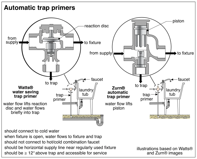 1643.5
Automatic trap primers
· p. 290
The illustration shows two automatic trap primer designs with enlarged sectional views and installation diagrams beside laundry tubs. The Watts water-saving primer uses a reaction disc lifted by supply flow to send water briefly to the trap, while the Zurn automatic primer uses a piston lifted by water flow. Arrows identify the supply inlet, outlet to the fixture, and downward outlet to the trap. The left installation shows the primer line extending beneath the floor to a floor-drain trap. Notes specify a cold-water connection on a horizontal supply line near a regularly used fixture, at least 12 inches above the trap and accessible for service, and warn against connection to a hot/cold combination faucet.
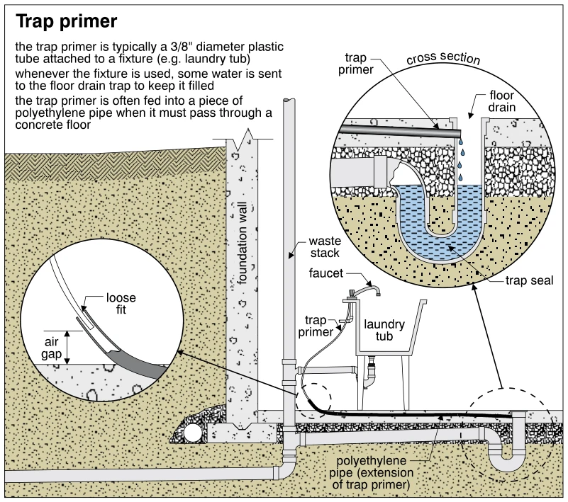 1644
1644Trap primer
· p. 290
The illustration shows a laundry tub faucet supplying a small plastic trap-primer tube that delivers water to a floor drain trap. The tube connects to a polyethylene pipe extension routed through the concrete floor to the drain. An enlarged detail identifies a loose fit and air gap at the tube-to-extension connection. A second enlarged cross section shows water dripping from the primer into the floor drain, maintaining the water-filled trap seal. The laundry tub waste piping connects separately to the waste stack beside the foundation wall.
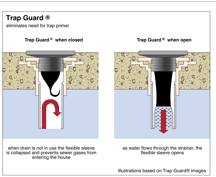 1644.3
Trap Guard ®
· p. 291
Two cross-sectional views show a Trap Guard insert installed beneath a floor-drain strainer in a concrete floor. In the left view, the flexible sleeve is collapsed while the drain is not in use, and a curved arrow indicates sewer gases being blocked from entering the house. In the right view, the sleeve opens to allow water to discharge downward through the drain. The illustration states that this device eliminates the need for a trap primer.
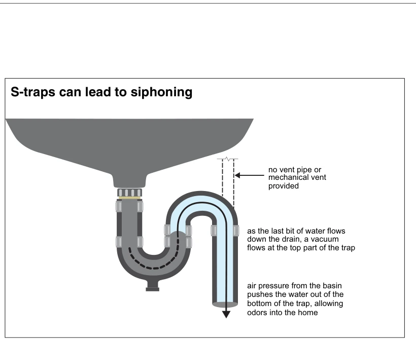 1644.6
S-traps can lead to siphoning
· p. 291
The illustration shows a basin draining through an S-trap into a vertical discharge pipe. A dashed outline marks the location of a missing vent pipe or mechanical vent. Arrows trace flow through the trap and down the discharge leg, illustrating siphoning as the last water drains. The annotations explain that a vacuum at the top of the trap and air pressure from the basin can remove the trap's water seal, allowing drain odors into the home.
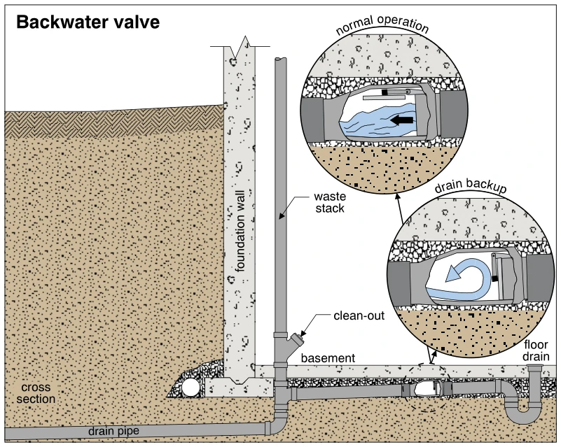 1645
1645Backwater valve
· p. 291
The illustration shows a basement plumbing cross section with a trapped floor drain connected to a waste stack and drain pipe beneath the slab. A backwater valve is installed in the horizontal floor-drain branch between the trap and waste stack. An enlarged view of normal operation shows the valve flap open, allowing drainage toward the stack. A second enlarged view shows reverse flow closing the flap during a drain backup, preventing backed-up wastewater from reaching the floor drain. The foundation wall, basement slab, surrounding soil, and a clean-out on the waste stack provide installation context.
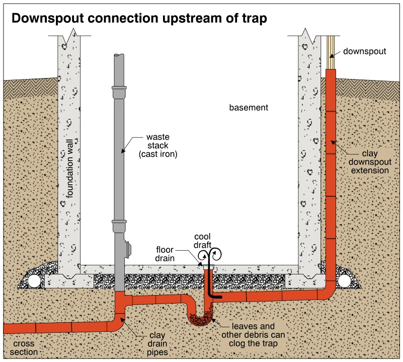 1646
1646Downspout connection upstream of trap
· p. 291
The cross section shows a basement floor drain with a below-slab trap connected to clay drain pipes serving a cast-iron waste stack. An exterior downspout enters a clay extension that runs down beside the foundation wall and beneath the basement slab, connecting upstream of the floor drain trap. Leaves and other debris are depicted accumulating in the bottom of the trap, with an annotation warning that they can clog it. Arrows at the floor drain indicate a cool draft entering the basement through this connection.
Drain, Waste And Vent Plumbing ·Venting Systemsp. 292
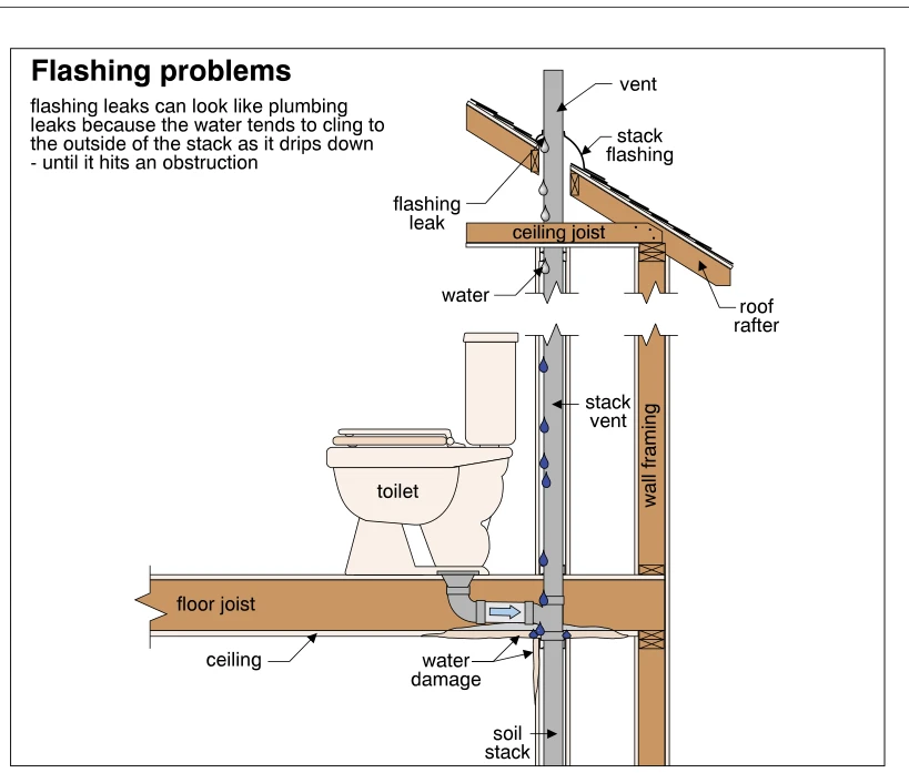 1647
1647Flashing problems
· p. 292
A sectional drawing shows a plumbing stack extending through a sloped roof, with stack flashing around the roof penetration. Water leaking at the flashing clings to the exterior of the stack and travels downward through the framed building. A toilet connects to the stack near floor level, where water collects around an obstruction and damages the ceiling below. The illustration explains how a roof flashing leak can appear to be a plumbing leak.
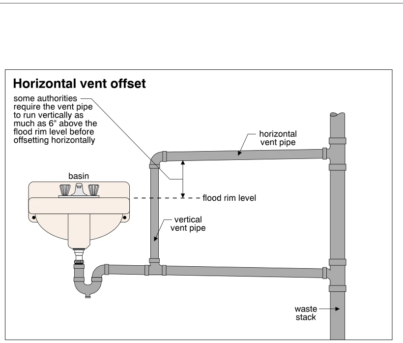 1648
1648Horizontal vent offset
· p. 292
The illustration shows a basin with a P-trap and a drain branch connected to a waste stack. A vertical vent pipe rises from the drain branch, then turns into a horizontal offset that connects to the stack above the drain connection. A dashed line marks the basin's flood rim level, with a vertical dimension indicating the height of the horizontal vent above it. The annotation states that some authorities require the vent to rise as much as 6 inches above the flood rim level before offsetting horizontally.
 1649
1649Vent on the wrong side of the trap
· p. 292
The illustration shows a basin drain connected through a trap to a horizontal branch leading to a vertical stack. A vent rises from the fixture side of the trap and runs back to the stack above the drain connection. A red prohibition symbol marks this vent arrangement as incorrect because the vent connects on the wrong side of the trap. Black arrows show sewer gas traveling up through the basin, bypassing the trap seal via the improperly connected vent. Slope arrows indicate the vent pitching toward the fixture connection and the drain pitching toward the stack, with the drain labeled 1/4 inch per foot.
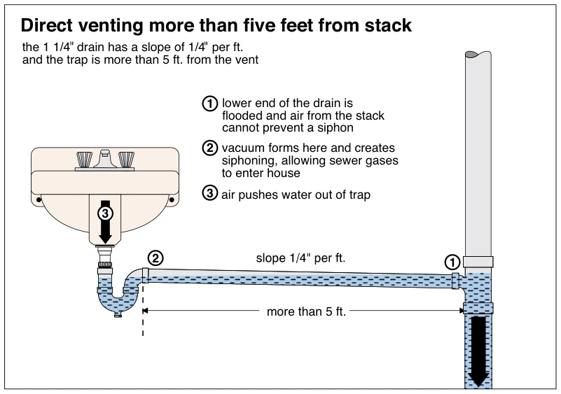 1649.5
Direct venting more than five feet from stack
· p. 292
The illustration shows a sink with a P-trap connected by a long, sloping drain to a vertical drain and vent stack. The 1 1/4-inch drain slopes 1/4 inch per foot, and the trap is more than five feet from the stack vent. Water fills the lower end of the drain at the stack connection, blocking the air path that would prevent siphoning. Numbered annotations identify the resulting vacuum near the trap and air pushing water out of the trap, causing loss of the trap seal and allowing sewer gases into the house.
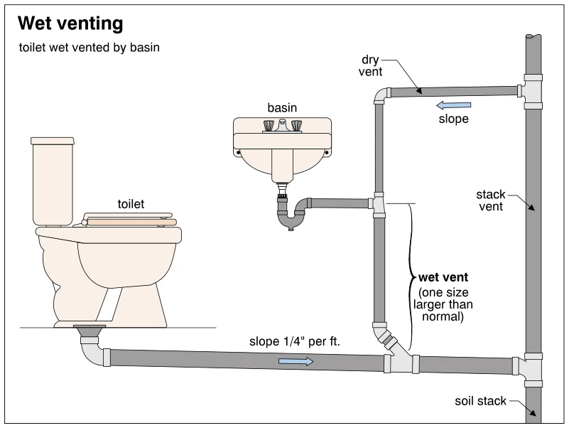 1650
1650Wet venting
· p. 292
The diagram shows a toilet wet vented through a basin drain connection. The basin discharges through a P-trap into a vertical pipe whose lower section connects to the toilet's horizontal drain and is labeled as a wet vent one size larger than normal. Above the basin connection, a dry vent rises and turns toward the stack vent, with a slope arrow pointing back toward the basin vent riser. The toilet drain slopes toward the soil stack at a labeled rate of 1/4 inch per foot. The right-hand vertical stack is identified as a stack vent above the drainage connection and a soil stack below it.
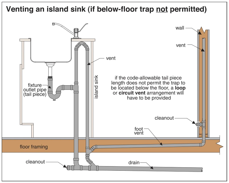 1651
1651Venting an island sink (if below-floor trap not permitted)
· p. 292
The illustration shows an island sink with its trap above the floor, connected to a vertical drain that extends below the floor framing. A loop vent rises within the island cabinet, bends over near the underside of the countertop, and returns downward through the floor. Below the floor, the returning vent connects to the drain and to a foot vent running toward a vertical vent in a nearby wall. Cleanouts are shown at the below-floor drain connection and at the wall vent. The annotation specifies a loop or circuit vent arrangement when the code-allowable tailpiece length does not permit a below-floor trap.
Drain, Waste And Vent Plumbing ·Sewage Ejector Pumpsp. 293
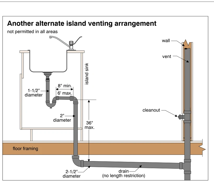 1652
1652Another alternate island venting arrangement
· p. 293
The illustration shows an alternate island sink drainage and venting arrangement, with a note that it is not permitted in all areas. A 1-1/2-inch sink tailpiece feeds a trap whose horizontal outlet is marked 8 inches minimum and 6 feet maximum before turning downward into a 2-inch pipe. The vertical drop to the underfloor drain is marked 36 inches maximum. Below the floor framing, a 2-1/2-inch drain marked as having no length restriction runs to a vertical pipe in a nearby wall. That wall pipe extends upward as a vent and includes an accessible cleanout above the floor.
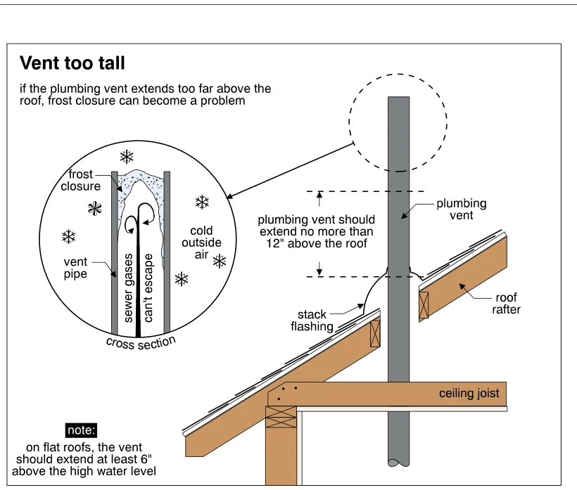 1653
1653Vent too tall
· p. 293
The illustration shows a plumbing vent extending excessively high above a sloped roof, with stack flashing at the roof penetration and adjacent roof rafters and a ceiling joist. A circular cross-section inset depicts frost closing the vent opening in cold outside air, preventing sewer gases from escaping. A dimension annotation states that the vent should extend no more than 12 inches above the roof. A separate note states that on flat roofs the vent should extend at least 6 inches above the high water level.
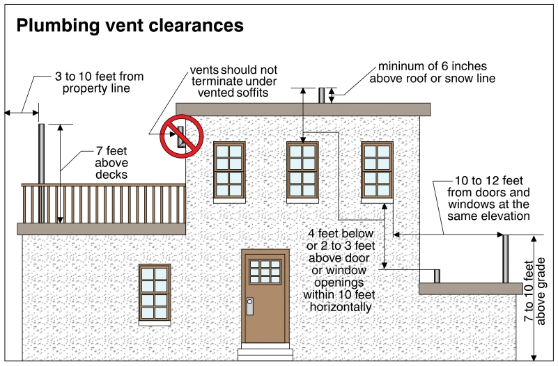 1654
1654Plumbing vent clearances
· p. 293
The illustration shows a house elevation with plumbing vent terminals at several locations and dimension arrows indicating clearances from roofs, decks, grade, property lines, doors, and windows. A roof vent is labeled for a minimum extension of 6 inches above the roof or snow line, and a vent beside the deck is shown extending 7 feet above the deck. Other annotations specify horizontal and vertical separation from door and window openings and a height of 7 to 10 feet above grade. A red prohibition symbol marks a vent terminating beneath a vented soffit as improper.
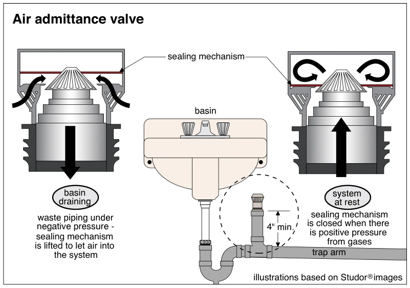 1654.5
Air admittance valve
· p. 293
The illustration shows an air admittance valve installed on a vertical riser from a basin's trap arm, with a minimum height of 4 inches indicated above the trap arm. Two enlarged valve cross-sections explain its operation. When the basin drains, negative pressure in the waste piping lifts the sealing mechanism and draws air into the system. At rest or under positive pressure from gases, the sealing mechanism closes to prevent gases from escaping through the valve. The basin, drain tailpiece, P-trap, and horizontal trap arm provide the installation context.
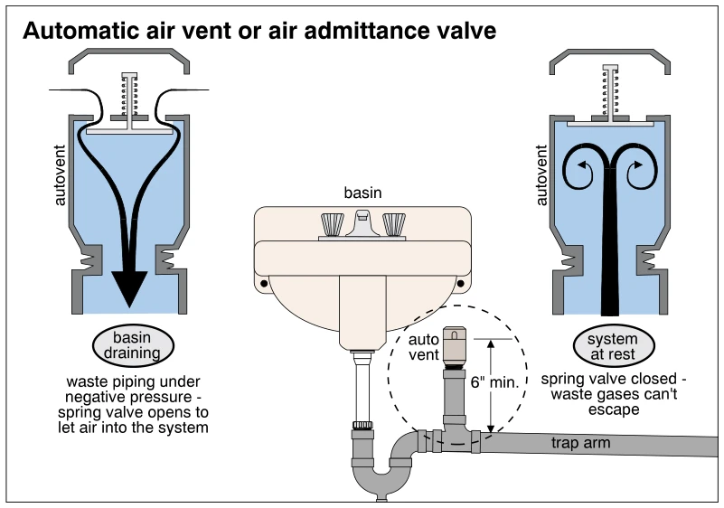 1655
1655Automatic air vent or air admittance valve
· p. 293
The illustration shows a basin draining through a P-trap and trap arm, with an automatic air vent mounted on a vertical riser connected to the trap arm. A dimension indicates a minimum height of 6 inches above the trap arm for the vent. The left sectional detail shows negative pressure during basin drainage opening a spring-loaded valve to admit air into the waste piping. The right sectional detail shows the valve closed when the system is at rest, preventing waste gases from escaping.
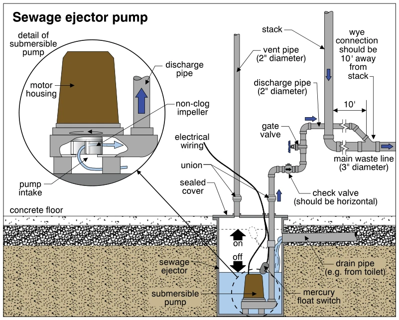 1656
1656Sewage ejector pump
· p. 293
The illustration shows a sewage ejector basin below a concrete floor, receiving wastewater through a drain pipe and pumping it up to an elevated main waste line. A submersible pump with a mercury float switch sits inside the basin beneath a sealed cover, with separate vent and discharge pipes passing through the cover. The discharge piping includes unions, a horizontal check valve, and a gate valve before connecting to the main waste line through a wye; an annotation specifies that the wye should be 10 feet away from the stack. Arrows indicate wastewater flow and the float switch's on and off positions. An enlarged pump detail identifies the motor housing, non-clog impeller, pump intake, and discharge pipe.
Drain, Waste And Vent Plumbing ·Septic Systemsp. 294
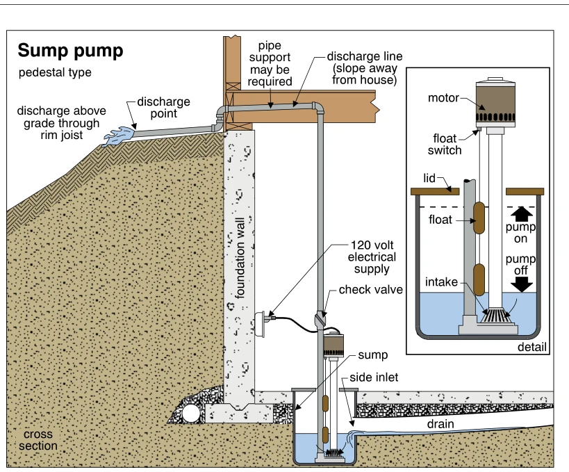 1657
1657Sump pump
· p. 294
The cross section shows a pedestal-type sump pump in a basin below the basement floor beside the foundation wall, receiving water through a side-inlet drain. The pump discharges through a vertical pipe with a check valve, then through the rim joist to an above-grade discharge point outside. The exterior discharge line is labeled to slope away from the house, with pipe support potentially required. An enlarged detail shows the motor above the sump lid, the intake near the basin bottom, and float positions that switch the pump on at a higher water level and off at a lower level. A 120-volt electrical supply is shown beside the pump.
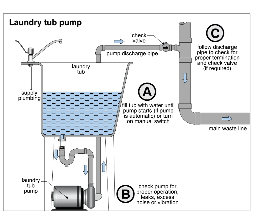 1658
1658Laundry tub pump
· p. 294
The illustration shows a laundry tub draining through a trap into a pump mounted beneath the tub. The pump lifts wastewater through a vertical discharge pipe, which turns horizontally and connects through a check valve to the main waste line. Blue arrows indicate flow from the tub to the pump and onward into the waste line. Three inspection annotations instruct the inspector to fill the tub and start the pump, check for proper operation, leaks, excess noise or vibration, and trace the discharge pipe for proper termination and a check valve if required. No specific defect is depicted.
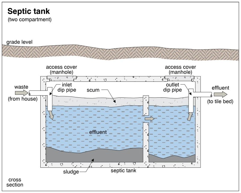 1659
1659Septic tank
· p. 294
The cross section depicts a buried, two-compartment septic tank with an access cover above each compartment. Waste from the house enters the larger first compartment through an inlet dip pipe, which directs flow below the floating scum layer. Sludge collects at the bottom, with liquid effluent between the sludge and scum layers. An opening in the dividing wall allows effluent to flow into the second compartment, where scum and sludge layers are also shown. An outlet dip pipe draws liquid from below the scum layer and directs effluent toward the tile bed.
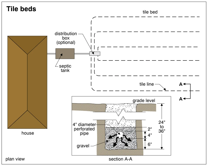 1660
1660Tile beds
· p. 294
The plan view shows a house connected to a septic tank, followed by an optional distribution box feeding multiple tile lines in a tile bed. Section A-A shows a 4-inch-diameter perforated pipe surrounded by gravel in a buried trench. Arrows indicate effluent dispersing outward and downward from the pipe into the gravel. The section specifies 2 inches of gravel above the pipe and 6 inches below it, with the trench bottom 24 to 36 inches below grade.
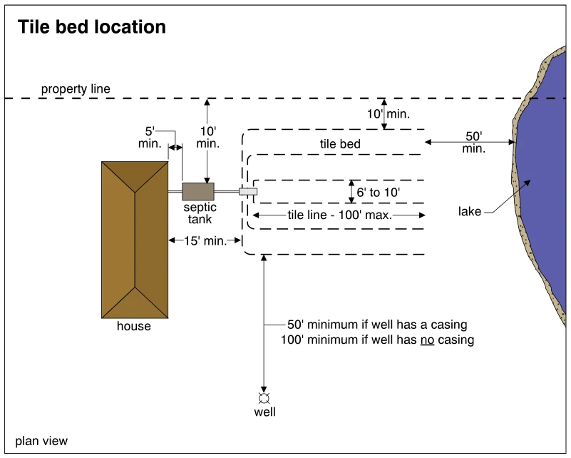 1661
1661Tile bed location
· p. 294
This plan view shows a house connected to a septic tank and tile bed, with a property line above, a lake to the right, and a well below. The illustrated minimum separations are 5 feet between the house and septic tank, 15 feet between the house and tile bed, and 10 feet from the property line to both the tank and tile bed. Parallel tile lines are spaced 6 to 10 feet apart and labeled as having a maximum length of 100 feet. The tile bed is shown at least 50 feet from the lake. Well separation is labeled as a minimum of 50 feet for a well with a casing and 100 feet for a well without a casing.
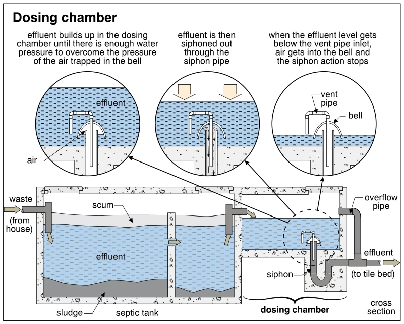 1662
1662Dosing chamber
· p. 294
A cross section shows a compartmented septic tank discharging effluent into an adjacent dosing chamber. The septic tank contains a floating scum layer, liquid effluent, and settled sludge, with submerged inlet and outlet fittings. The dosing chamber contains a bell siphon, vent pipe, and an overflow pipe connected to the discharge toward the tile bed. Three enlarged details illustrate the operating sequence: rising effluent overcomes air pressure trapped in the bell, siphoning empties the chamber, and air entering the exposed vent pipe inlet stops the siphon. The drawing explains normal operation rather than depicting a defect.
Fixtures And Faucets ·Faucetsp. 295
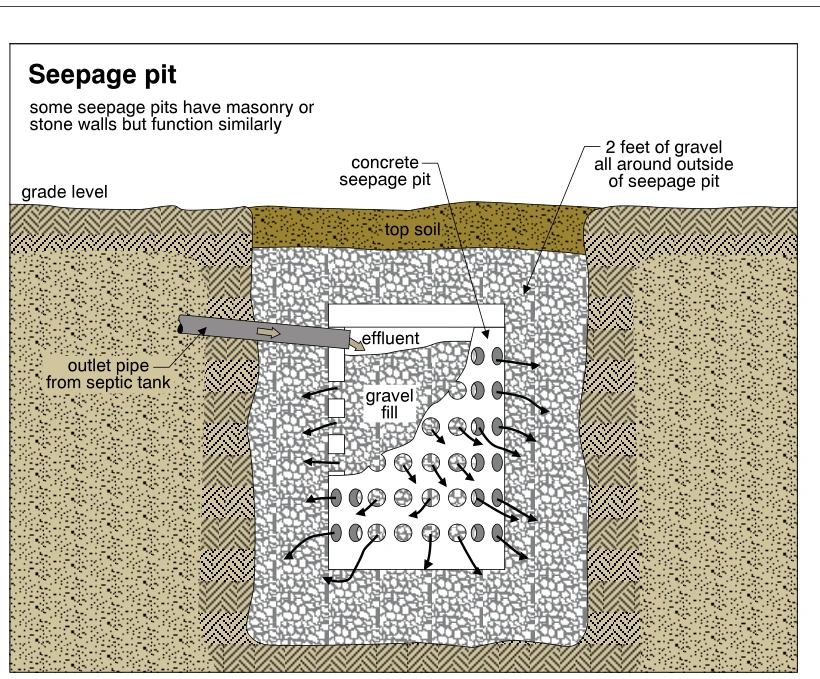 1663
1663Seepage pit
· p. 295
The illustration shows a below-grade concrete seepage pit receiving effluent through an outlet pipe from a septic tank. A cutaway exposes gravel fill inside the pit and numerous openings in its walls. Arrows show effluent passing outward through the openings into the surrounding gravel. The pit is surrounded by a gravel envelope labeled as 2 feet thick, with topsoil covering the excavation at grade. A note states that some seepage pits have masonry or stone walls but function similarly.
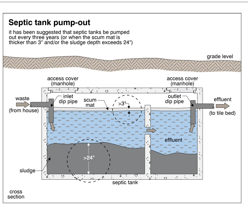 1664
1664Septic tank pump-out
· p. 295
A cross section shows a buried, two-compartment septic tank with access covers, inlet and outlet dip pipes, and an internal partition with a transfer opening. Arrows trace wastewater from the house through the tank and effluent out toward the tile bed. A scum mat floats above the liquid, while sludge accumulates at the bottom of both compartments. Dimension annotations highlight scum thicker than 3 inches and sludge deeper than 24 inches as pump-out triggers. The printed note suggests pumping every three years or when these accumulation thresholds are exceeded.
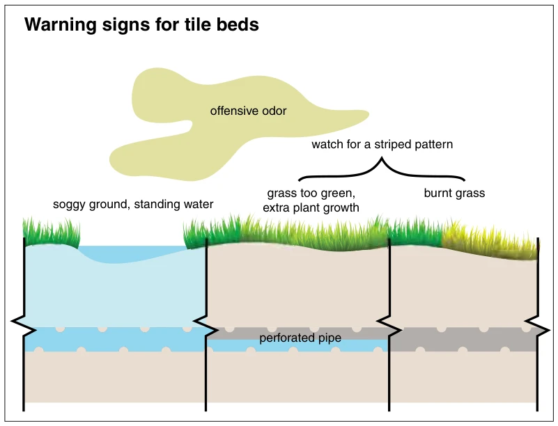 1664.5
Warning signs for tile beds
· p. 295
The illustration shows a sectional view of a septic tile bed with perforated pipe buried beneath soil and grass. Warning signs at the surface include soggy ground and standing water, unusually green grass or extra plant growth, and burnt grass. A bracket advises watching for a striped pattern in the vegetation above the bed. A cloud labeled offensive odor identifies another warning sign of potential tile-bed problems.
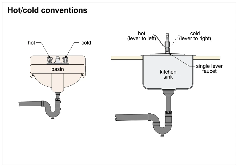 1665
1665Hot/cold conventions
· p. 295
The illustration shows hot- and cold-water control conventions for a two-handle basin faucet and a single-lever kitchen faucet. The basin has the hot-water handle on the left and the cold-water handle on the right. The kitchen faucet delivers hot water with the lever moved left and cold water with the lever moved right, as indicated by the lever positions above the sink. Both fixtures are shown with drain tailpieces and P-traps below them.
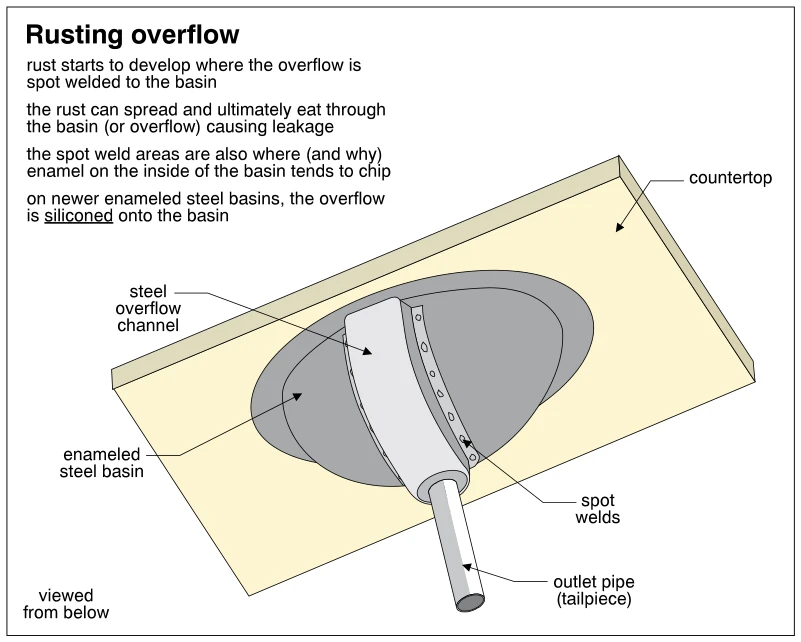 1666
1666Rusting overflow
· p. 295
The illustration shows an enameled steel basin mounted in a countertop, viewed from below. A steel overflow channel follows the underside of the basin to the outlet pipe (tailpiece), with spot welds along its attachment flange. The annotations explain that rust can develop at these welds and eventually perforate the basin or overflow channel, causing leakage. They also identify the weld areas as locations where the interior enamel tends to chip and note that newer enameled steel basins use silicone to attach the overflow.
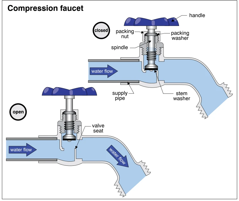 1667
1667Compression faucet
· p. 295
Two sectional views show a compression faucet in its closed and open positions. In the upper view, the threaded spindle holds the stem washer against the valve seat, blocking flow from the supply pipe to the spout. In the lower view, the spindle and stem washer are raised, allowing water to pass through the valve seat and out the spout, as indicated by arrows. The handle operates the spindle, while the packing nut and packing washer surround the spindle at the top of the faucet body.
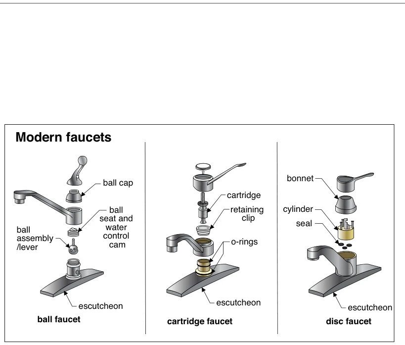 1667.5
Modern faucets
· p. 296
The illustration presents exploded views of three single-lever faucet designs: ball, cartridge, and disc. The ball faucet shows the handle, ball cap, ball seat and water control cam, and ball assembly/lever above the mounting base. The cartridge faucet shows a removable cartridge, retaining clip, and O-rings within the spout and base assembly. The disc faucet shows a bonnet, cylinder, and seals beneath the lever handle. Each faucet has an escutcheon at its base; no defects or improper installation practices are depicted.
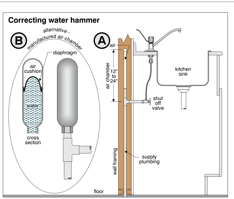 1668
1668Correcting water hammer
· p. 296
The illustration shows two arrangements for correcting water hammer at a kitchen sink supply. Arrangement A uses a capped vertical air chamber extending 12 to 24 inches above the branch connection to the shutoff valve, alongside the wall framing. The shutoff valve connects to the sink faucet through a supply tube. Arrangement B shows an alternative manufactured air chamber attached to a supply tee. Its cross section depicts a diaphragm separating the water from an air cushion.
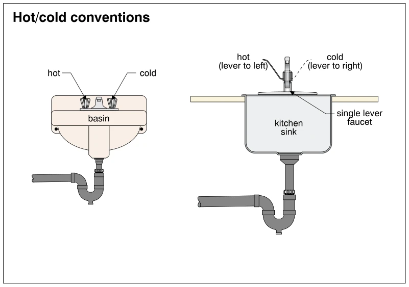 1669
1669Hot/cold conventions
· p. 296
The illustration shows a basin with separate hot and cold faucet handles alongside a kitchen sink with a single-lever faucet. At the basin, the hot handle is on the user's left and the cold handle is on the right. For the single-lever faucet, arrows indicate movement to the left for hot water and to the right for cold water. Both fixtures are shown with drain tailpieces and P-traps beneath them. The drawing illustrates conventional faucet temperature-control orientation, with no defects depicted.
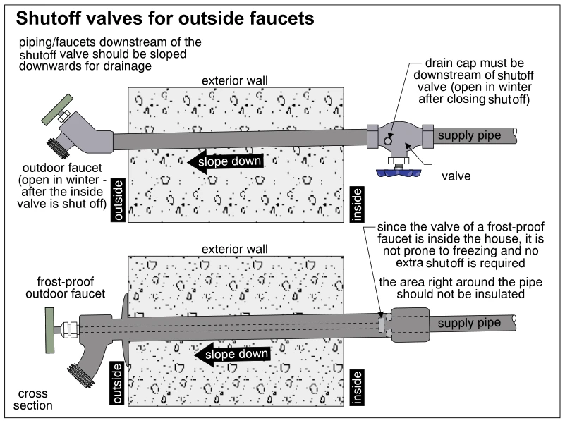 1670
1670Shutoff valves for outside faucets
· p. 296
Two wall sections illustrate freeze-protection arrangements for outside faucets. The upper drawing shows a conventional outdoor faucet connected to an indoor shutoff valve with a drain cap on the downstream side; the annotations instruct opening the faucet and drain cap in winter after closing the shutoff. The lower cross section shows a frost-proof faucet with a long stem placing its valve inside the house, and notes that no extra shutoff is required. Both assemblies slope downward toward the exterior for drainage. The frost-proof detail also states that the area immediately around the pipe should not be insulated.
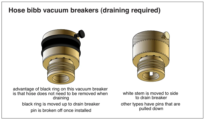 1670.5
Hose bibb vacuum breakers (draining required)
· p. 296
The illustration shows two hose bibb vacuum breakers with threaded hose outlets and different manual draining mechanisms. The left breaker has a black ring that is moved upward to drain the device without removing the hose. An annotation states that the pin is broken off once installed. The right breaker has a white stem inside its outlet that is moved sideways to drain it; the accompanying text notes that other types use pins pulled downward. The title emphasizes that these vacuum breakers require draining.
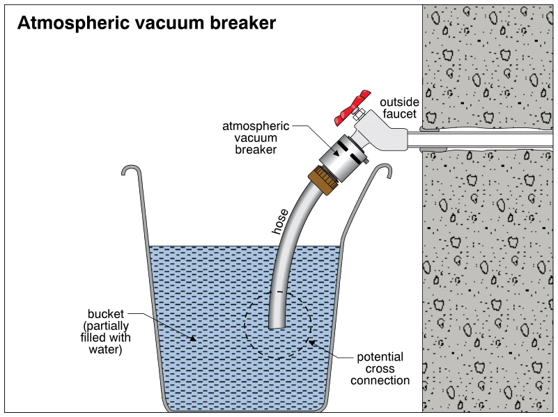 1671
1671Atmospheric vacuum breaker
· p. 296
An outside faucet projects through a wall and has an atmospheric vacuum breaker installed between its outlet and a hose. The hose extends into a bucket partially filled with water, with its open end submerged. A dashed circle and callout identify the submerged hose end as a potential cross connection. The vacuum breaker provides protection against backsiphonage of bucket water into the potable water supply.
Fixtures And Faucets ·Toiletsp. 297
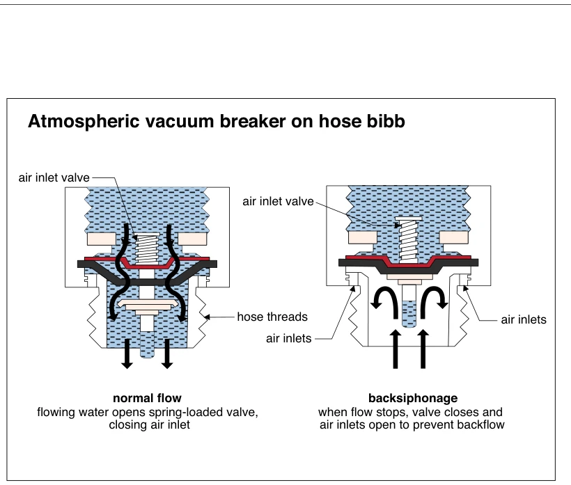 1671.5
Atmospheric vacuum breaker on hose bibb
· p. 297
Two sectional diagrams show an atmospheric vacuum breaker fitted to a hose bibb outlet, with hose threads at the bottom. In the normal-flow diagram, water opens the spring-loaded valve and closes the air inlet; arrows show water flowing downward through the device. In the backsiphonage diagram, the valve closes when flow stops and the side air inlets open to prevent backflow. The diagrams illustrate operating states of the backflow-protection device rather than an installation defect.
 1672
1672Toilet flushing actions
· p. 297
Two cutaway toilet diagrams compare siphon vortex and siphon jet flushing actions. Both show water flowing from the tank through rim openings into the bowl and then through the integral trapway to the drain beneath the floor. The siphon vortex diagram depicts swirling water at the bottom of the bowl, while the siphon jet diagram shows an additional water passage supplying a jet directed toward the trapway. Arrows indicate flushing flow, and a note specifies that the illustrated water levels are during flushing. The siphon jet arrangement is annotated as providing a quieter flush and being typically found on more expensive toilets.
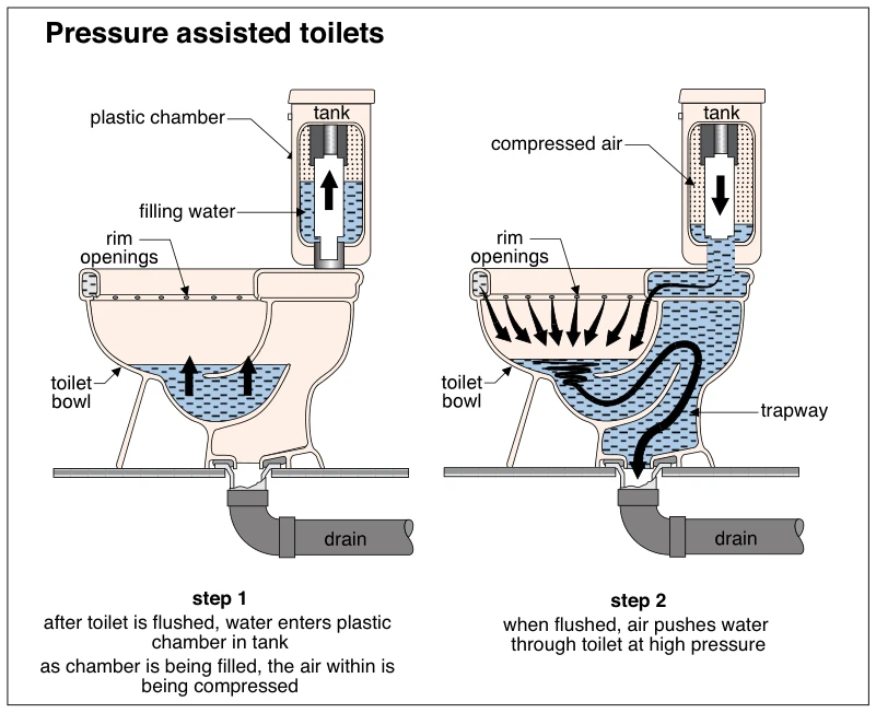 1672.5
Pressure assisted toilets
· p. 297
Two sectional views illustrate the filling and flushing stages of a pressure-assisted toilet. In step 1, water enters a plastic chamber inside the tank, compressing the air within it; arrows also show the bowl refilling. In step 2, compressed air pushes water from the chamber into the toilet at high pressure. Flow arrows trace water through the rim openings and bowl, then through the curved trapway into the drain below the floor. The illustration explains normal operation rather than depicting a defect.
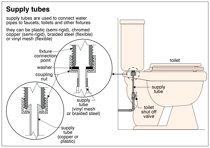 1673
1673Supply tubes
· p. 297
The illustration shows a toilet supply tube connecting a wall-fed shutoff valve to the underside of the toilet tank. Two enlarged sectional details show supply-tube connections to a threaded fixture connection point using coupling nuts. The flexible vinyl-mesh or braided-steel tube detail identifies a washer at the sealing interface, while the copper or plastic tube detail shows a shaped tube end captured by the coupling nut. The annotations distinguish semi-rigid plastic and chromed copper tubes from flexible braided steel and vinyl mesh tubes. No defective installation is depicted.
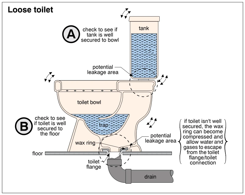 1674
1674Loose toilet
· p. 297
A sectional drawing of a two-piece toilet shows the tank, bowl, integral trap, wax ring, toilet flange, and drain connection beneath the floor. Movement arrows indicate looseness at the tank and toilet body. Check A calls for verifying that the tank is secured to the bowl, with a potential leakage area identified at their connection. Check B calls for verifying that the toilet is secured to the floor, with another potential leakage area identified at the wax ring. The annotation explains that movement can compress the wax ring and allow water and gases to escape at the toilet-to-flange connection.
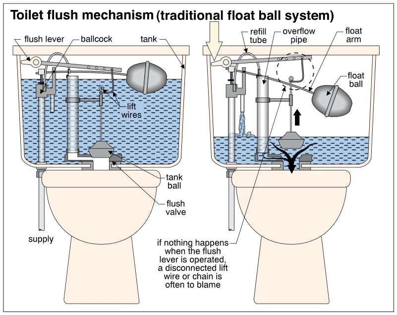 1675
1675Toilet flush mechanism (traditional float ball system)
· p. 297
Two cutaway views depict a toilet with a traditional float-ball-operated ballcock, first with the tank full and then during flushing. In the full tank, the float ball is raised and the tank ball rests on the flush valve opening. Operating the flush lever raises the tank ball through the lift wires, allowing water to discharge into the bowl. As the water level drops, the float arm lowers and the ballcock admits supply water; a refill tube leads into the overflow pipe. An annotation identifies a disconnected lift wire or chain as a possible cause when operating the lever produces no flush.
Fixtures And Faucets ·Tub and Shower Enclosuresp. 298
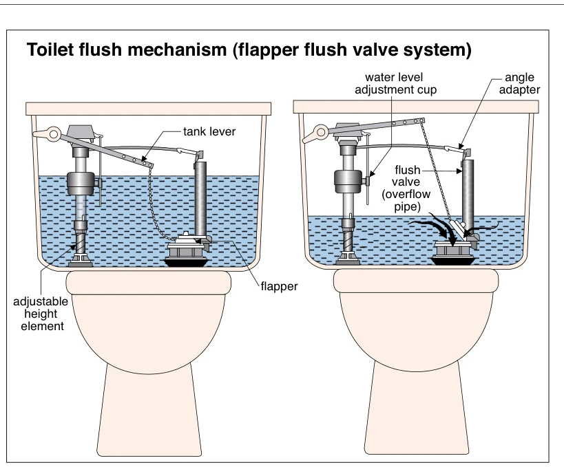 1675.5
Toilet flush mechanism (flapper flush valve system)
· p. 298
Two cutaway views of a toilet tank illustrate a flapper-type flush mechanism before and during flushing. The left view shows a filled tank with the flapper seated over the flush valve outlet and a chain connecting it to the tank lever. The right view shows the lever raised, the chain lifting the flapper, and arrows indicating water flowing toward the open outlet as the tank water level drops. An adjustable-height fill valve and water level adjustment cup are shown on the left side of each tank, with a small tube extending to an angle adapter at the overflow pipe.
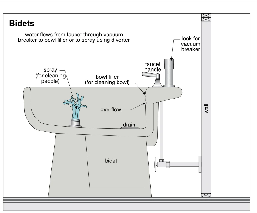 1676
1676Bidets
· p. 298
A sectional drawing shows a floor-mounted bidet beside a wall, with a wall-connected water supply and shutoff valve. A faucet handle and raised vacuum breaker are mounted at the rear of the fixture. The annotation explains that water flows through the vacuum breaker and is directed by a diverter to either the bowl filler or the upward-facing personal-cleaning spray. The bowl includes an overflow opening and a drain, and a callout specifically advises looking for the vacuum breaker.
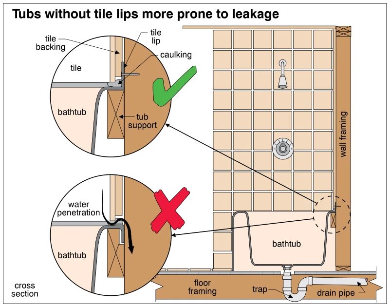 1677
1677Tubs without tile lips more prone to leakage
· p. 298
The illustration shows a cross section of a bathtub and tiled shower enclosure, including wall framing, floor framing, and the tub drain and trap. Two enlarged details compare the tub-to-tile junction with and without a tile lip. The upper detail, marked with a green check, shows an upturned tub lip behind the tile, caulking at the junction, and support beneath the tub rim. The lower detail, marked with a red X, shows water penetrating the junction of a tub without a tile lip and flowing down behind the bathtub.
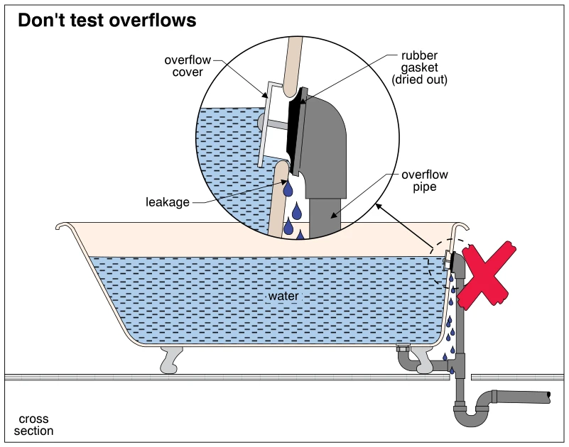 1678
1678Don't test overflows
· p. 298
A cross section shows a bathtub filled with water to the overflow opening, with its drain, overflow pipe, and trap visible. An enlarged detail shows the overflow cover and a dried-out rubber gasket between the tub wall and overflow fitting. Water leaks through this connection and runs down outside the overflow pipe toward the floor. A large red X and the title warn against testing bathtub overflows.
 1679
1679Inspecting a bathtub
· p. 298
The illustration shows a bathtub with a tiled wall surround, showerhead, faucet control, tub spout, and recessed soap dish. Lettered inspection points identify fixture operation, drainage from the tub perimeter into the basin, and the condition of tiles and their backing. Other checkpoints address damage at tub-to-wall and tub-to-floor intersections, springiness or rot in the floor in front of the tub, and trapped water beneath an added tub liner. Arrows indicate water draining inward from the tub perimeter. These are inspection instructions rather than confirmed defects; the shower rod and curtain are explicitly omitted for clarity.
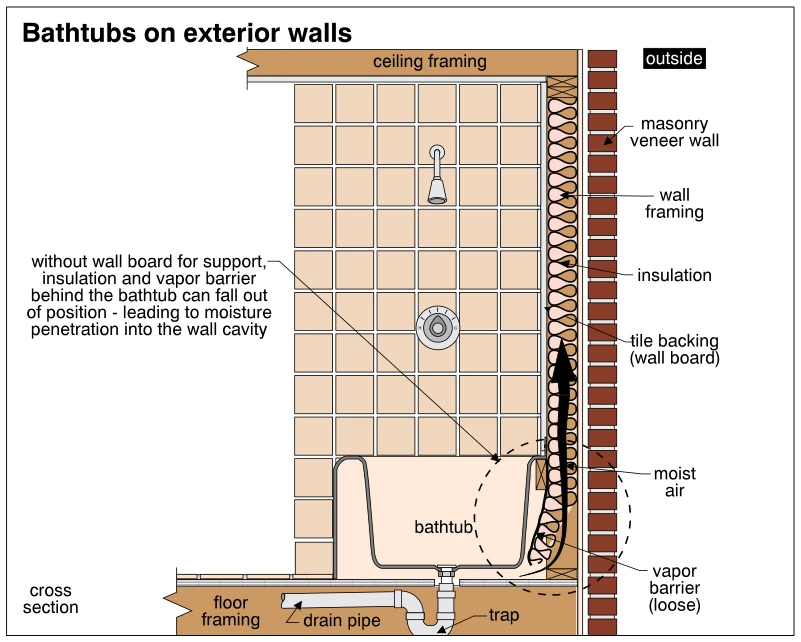 1680
1680Bathtubs on exterior walls
· p. 298
The illustration shows a cross section of a bathtub and tiled shower enclosure against an insulated exterior wall with masonry veneer. Tile backing is shown above the tub, but wall board support is missing behind the bathtub. Insulation and a loose vapor barrier have fallen out of position in this concealed area. A large upward arrow shows moist air entering and rising through the wall cavity, illustrating the moisture-penetration risk. The tub drain connects to a trap and horizontal drain pipe within the floor framing.
Fixtures And Faucets ·Shower Stallsp. 299
 1681
1681Bathtub windows aren't a good idea
· p. 299
The illustration shows a bathroom with a bathtub and shower surrounded by tiled walls, with a window located in the wall above the tub. A red prohibition symbol overlays the window, identifying this location as undesirable. Arrows point to areas beneath the window where window rot, wall stud rot, soft tile backing, and loose tiles can occur. An annotation states that a waterproof curtain over the window may help but may not provide a positive solution. A pedestal sink, mirror, and open bathroom door are also shown; the shower rod and curtain are explicitly omitted for clarity.
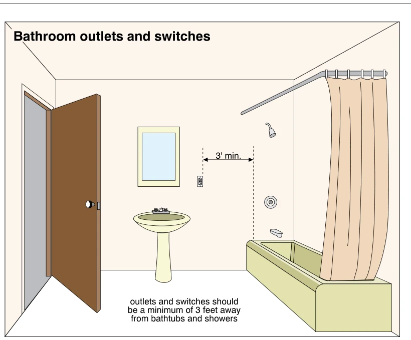 1682
1682Bathroom outlets and switches
· p. 299
The illustration shows a bathroom with a pedestal sink, mirror, and bathtub/shower combination with a shower curtain. A wall-mounted electrical device is positioned between the sink and the bathing area. A horizontal dimension marks a minimum separation of 3 feet between the electrical-device location and the edge of the bathtub/shower area. The annotation presents this separation as the recommended placement for bathroom outlets and switches.
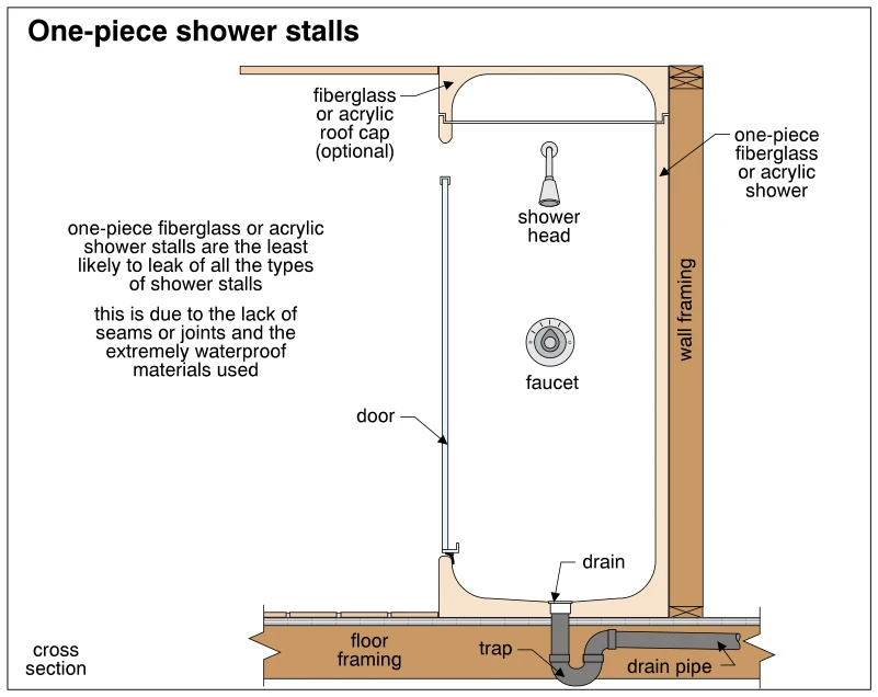 1683
1683One-piece shower stalls
· p. 299
A cross section shows a one-piece fiberglass or acrylic shower stall installed against wall framing and supported above floor framing. The molded enclosure incorporates the shower walls and base, with an optional fiberglass or acrylic roof cap above. A door closes the entrance, and a shower head and faucet are shown inside the enclosure. The base drain connects through the floor to a trap and horizontal drain pipe. An annotation explains that one-piece stalls are least likely to leak because they lack seams or joints and use extremely waterproof materials.
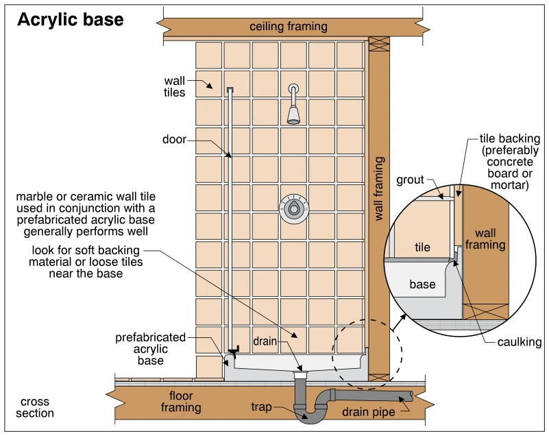 1684
1684Acrylic base
· p. 299
The illustration shows a cross section of a tiled shower stall with a prefabricated acrylic base, a door, and a drain connected to a trap and drain pipe below the floor. Wall and ceiling framing surround the enclosure. An enlarged detail shows the tile, grout, backing, and caulked junction between the tiled wall and the raised edge of the base. The annotations state that marble or ceramic wall tile used with a prefabricated acrylic base generally performs well and recommend concrete board or mortar backing. An inspection note advises looking for soft backing material or loose tiles near the base; these conditions are not explicitly drawn.
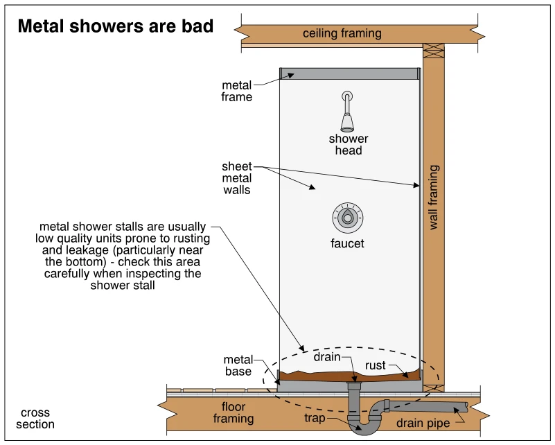 1685
1685Metal showers are bad
· p. 299
A cross section shows a metal shower stall with sheet metal walls, a metal frame, and a metal base adjacent to wall framing and beneath ceiling framing. A shower head and faucet are mounted on the stall wall. The base drain connects to a trap and drain pipe beneath the floor. Rust is depicted along the bottom of the stall, and a dashed oval highlights the base and lower wall area. The annotation warns that metal shower stalls are typically low-quality units prone to rusting and leakage, particularly near the bottom, and calls for careful inspection of this area.
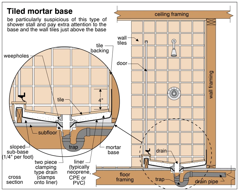 1686
1686Tiled mortar base
· p. 299
The illustration shows a tiled shower stall with a mortar base, together with an enlarged cross section of its floor and drain assembly. Floor tile rests on a mortar bed above a liner and a sub-base sloped toward the drain at 1/4 inch per foot. The liner turns up at the perimeter and is secured to a two-piece clamping drain, with weepholes allowing water at the liner level to enter the drain. A trap below the floor connects the drain to the drain pipe, and the section also shows the shower curb, door, tile backing, and surrounding framing. An annotation advises particular inspection attention to the base and wall tiles just above it; no specific failure is depicted.
Fixtures And Faucets ·Whirlpool Bathsp. 300
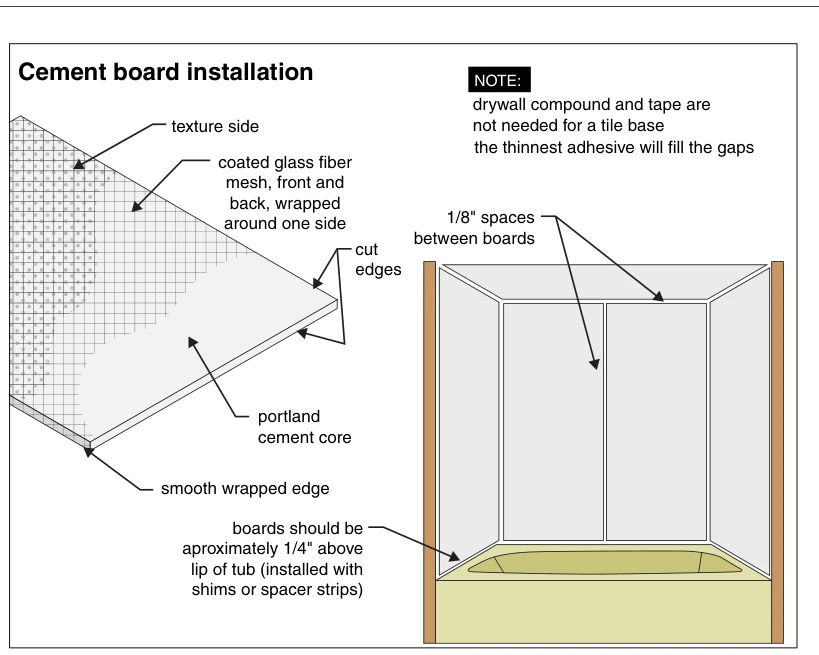 1686.3
Cement board installation
· p. 300
The illustration shows cement board construction alongside its installation as a bathtub surround tile base. The enlarged board detail identifies a Portland cement core, coated glass fiber mesh on both faces wrapping around one side, a textured face, cut edges, and a smooth wrapped edge. The surround diagram shows panels on three walls with 1/8-inch spaces between boards. The lower board edges are positioned approximately 1/4 inch above the tub lip using shims or spacer strips. A printed note states that drywall compound and tape are not needed for a tile base and that adhesive will fill the gaps.
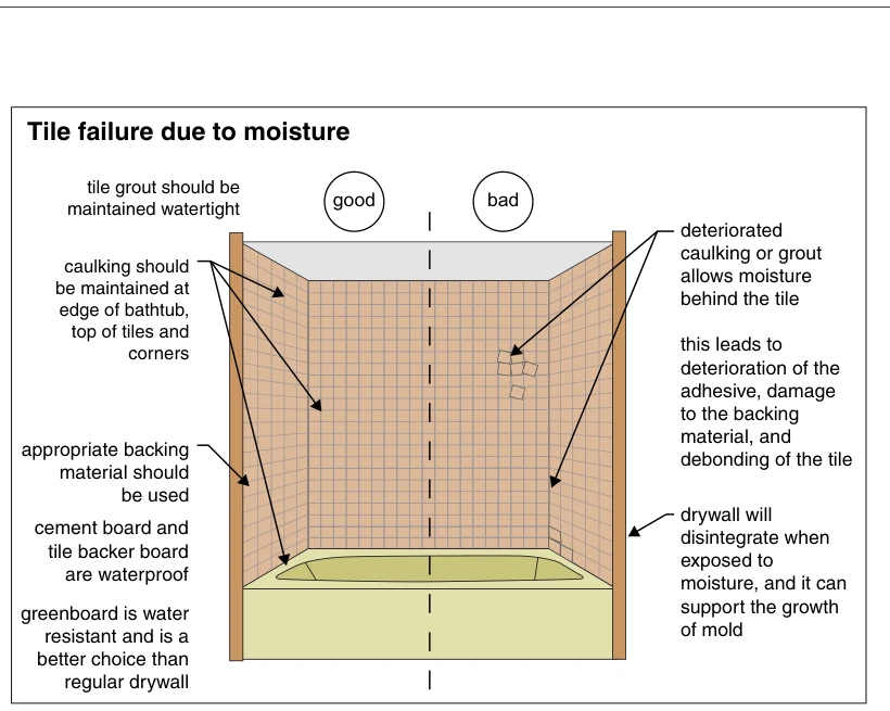 1686.6
Tile failure due to moisture
· p. 300
The illustration shows a bathtub with a three-sided tiled surround, divided by a dashed line into good and bad conditions. The good side identifies watertight grout, maintained caulking at the bathtub edge, tile tops and corners, and appropriate backing material. The bad side shows loose or debonding tiles and explains that deteriorated caulking or grout permits moisture behind the tile, damaging adhesive and backing. An additional annotation warns that moisture-exposed drywall can disintegrate and support mold growth.
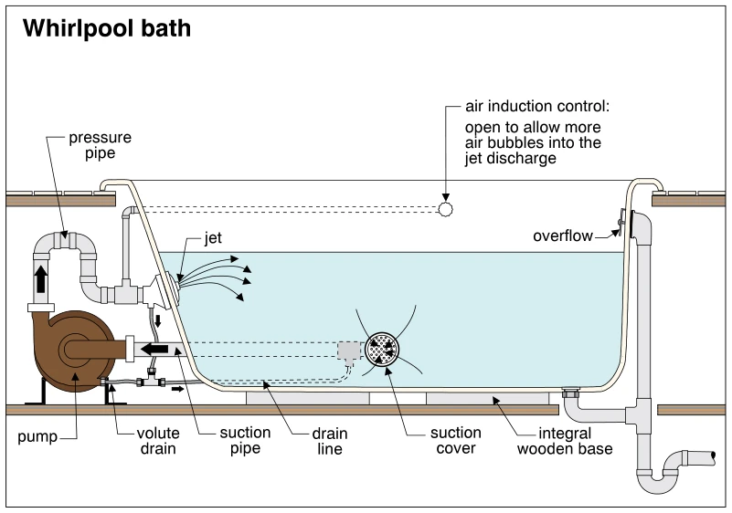 1687
1687Whirlpool bath
· p. 300
The illustration shows a sectional view of a filled whirlpool bathtub with its pump and associated piping. Directional arrows show water being drawn through the suction cover and suction pipe into the pump, then returned through the pressure pipe to a jet in the tub wall. An air induction control is connected to the jet assembly, with an annotation explaining that opening it introduces more air bubbles into the jet discharge. A volute drain and drain line are shown beneath the circulation piping. The tub rests on an integral wooden base, and its bottom drain and overflow connect to waste piping and a trap at the right.
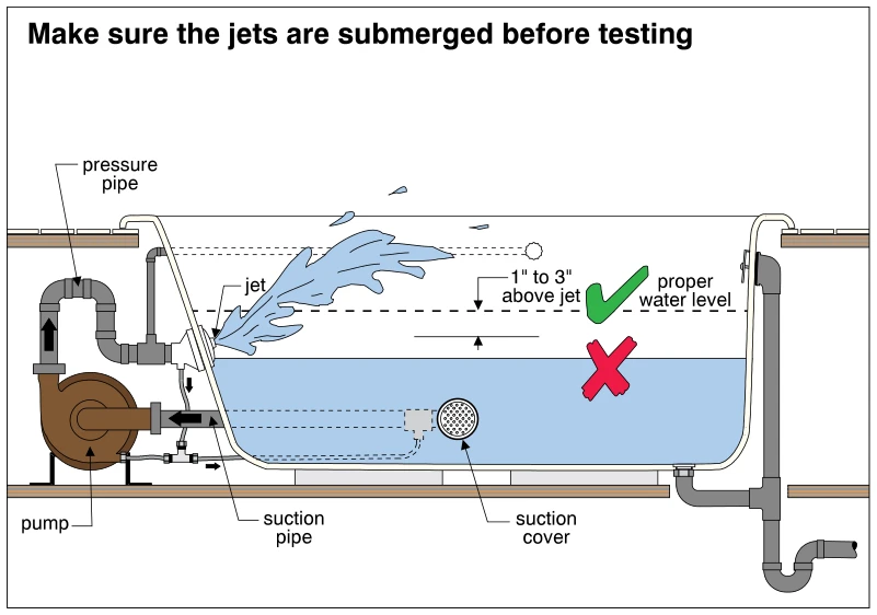 1688
1688Make sure the jets are submerged before testing
· p. 300
A cutaway view of a whirlpool bathtub shows the pump, pressure piping, wall jet, suction piping, and suction cover, along with the drain and overflow assembly. Arrows indicate circulation from the suction connection through the pump to the jet. The illustrated water level is below the jet, causing the exposed jet to spray above the water, and is marked with a red X. A dashed line marked with a green check indicates the proper testing water level, 1 to 3 inches above the jet.
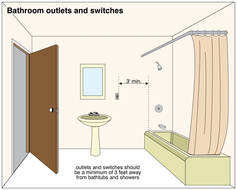 1689
1689Bathroom outlets and switches
· p. 300
The illustration shows a bathroom with a pedestal sink, mirror, and bathtub with a showerhead and curtain. A wall-mounted electrical device is positioned between the sink and the tub/shower area. A horizontal dimension marks a minimum separation of 3 feet between the electrical device location and the bathtub/shower boundary. The annotation presents this separation as the recommended placement for bathroom outlets and switches.