
Related illustrations
 1380
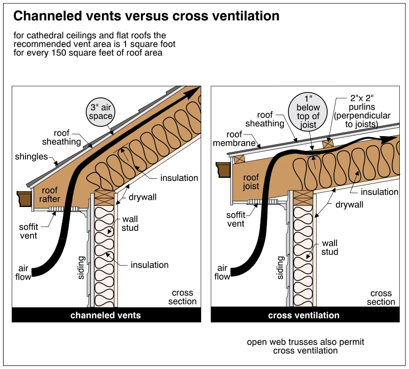
1380Channeled vents versus cross ventilation
· p. 250
Two roof-to-wall cross sections compare channeled ventilation with cross ventilation for cathedral ceilings and flat roofs. The left drawing shows air entering a soffit vent and traveling up a sloped shingle roof through
 0228
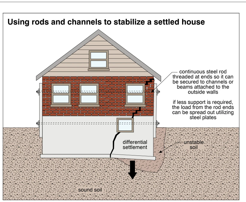
0228Using rods and channels to stabilize a settled house
· p. 37
The illustration shows a brick house with a below-grade foundation and footing affected by differential settlement on the right side. A zone of unstable soil beneath that side contrasts with the surrounding sound soil, a
 0365
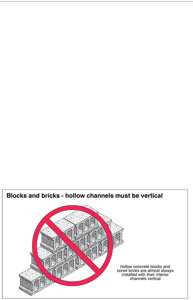
0365Blocks and bricks - hollow channels must be vertical
· p. 65
The illustration shows a stepped section of hollow masonry wall with staggered joints between units. The units are laid with their hollow channels running horizontally, exposing the openings on the wall face. A large red
 0265
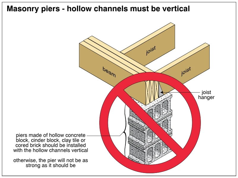
0265Masonry piers - hollow channels must be vertical
· p. 43
The illustration shows a built-up wood beam supported by a hollow masonry pier, with wood joists attached using joist hangers. The pier units are laid with their hollow channels horizontal, exposing the openings on the s
 2086
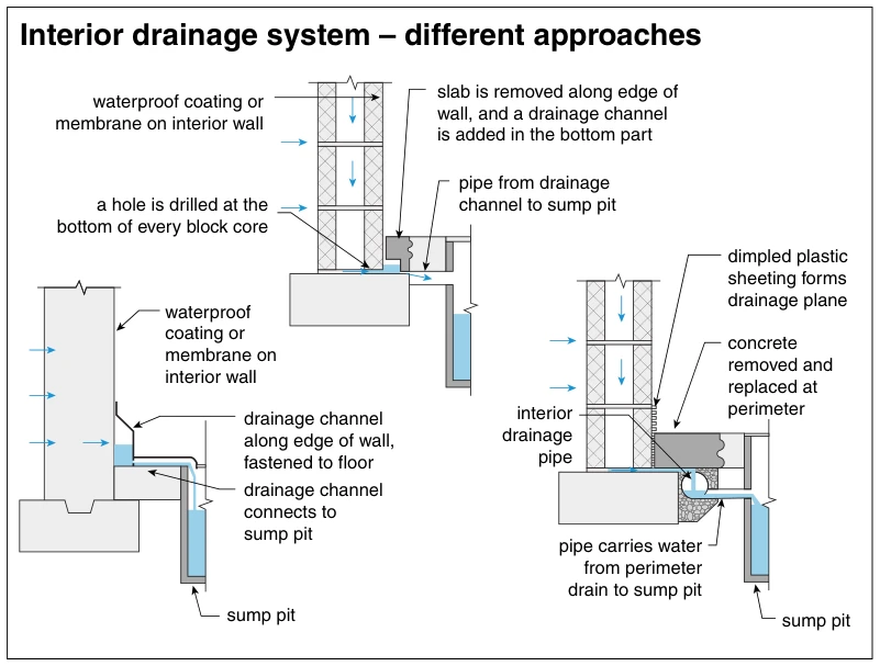
2086Interior drainage system – different approaches
· p. 372
Three cross-sectional details illustrate different interior basement drainage arrangements that direct water to sump pits. The upper detail shows holes drilled at the bottom of concrete block cores, an interior waterproo
 0362
0362Using rods and channels to stabilize a settled house
· p. 64
The illustration shows a masonry house with differential settlement at the right side, where unstable soil lies beneath the foundation. A large irregular crack extends through the foundation wall and continues as stepped
 0432.8
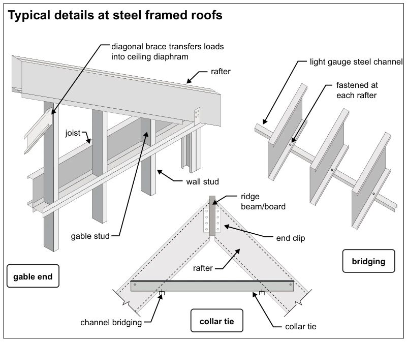
Typical details at steel framed roofs
· p. 79
Three details illustrate light-gauge steel roof framing at a gable end, rafter bridging, and a collar tie. The gable-end detail shows rafters, joists, wall studs, and gable studs, with a diagonal brace identified as tran
 0399.3
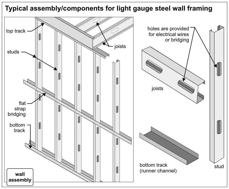
Typical assembly/components for light gauge steel wall framing
· p. 71
The illustration shows a light-gauge steel wall assembly with vertical studs seated in a bottom track and capped by a top track, with joists above. Horizontal flat strap bridging crosses the stud faces. Separate details