
02Structure
266 illustrations · printed pages 31-82
Footings And Foundations ·Descriptionp. 32
 0200
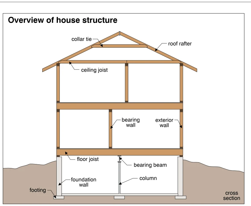
0200Overview of house structure
· p. 32
The illustration shows a cross section through a two-story house with a basement and a pitched roof. Roof rafters are connected by a collar tie, with ceiling joists spanning across the upper-story walls. Floor joists are supported by exterior walls and an interior bearing wall. At the basement level, a bearing beam rests on a central column, while foundation walls support the perimeter framing. Footings beneath the foundation walls and column distribute structural loads to the ground; no defects are indicated.
 0201
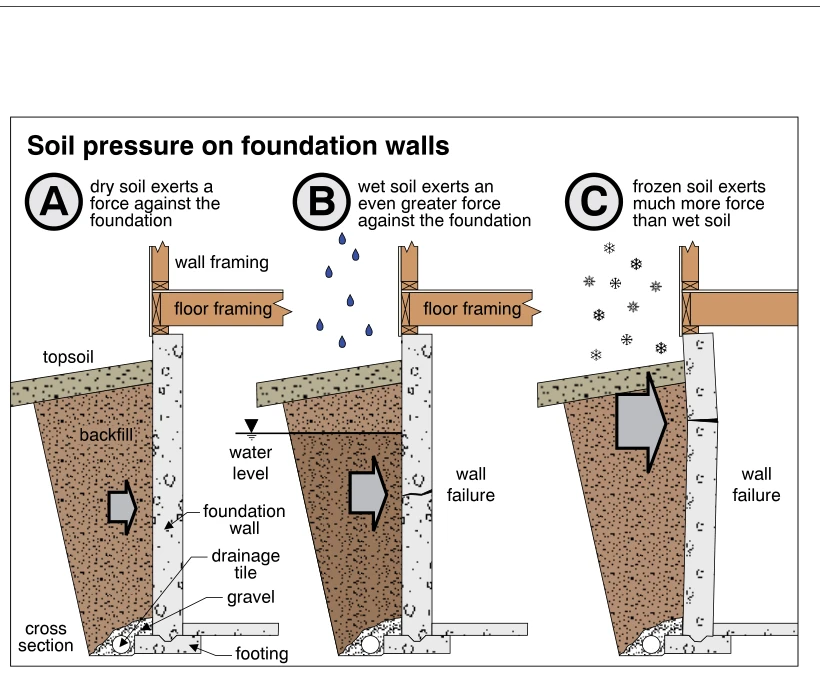
0201Soil pressure on foundation walls
· p. 32
Three cross sections compare lateral soil pressure against foundation walls under dry, wet, and frozen soil conditions. Each shows a foundation wall on a footing, adjacent backfill, drainage tile in gravel, and supported wood framing above. Increasingly large arrows indicate greater inward force from dry soil to wet soil to frozen soil. The wet-soil example includes a water-level line and a crack indicating wall failure. The frozen-soil example shows wall displacement and cracking, also labeled as wall failure.
 0202
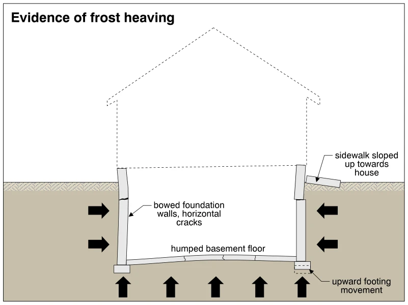
0202Evidence of frost heaving
· p. 32
The illustration shows a house foundation in section with surrounding soil and a basement floor. Large arrows indicate inward pressure against the foundation walls and upward pressure beneath the floor and footings. The left foundation wall bows inward and has a horizontal crack, while the basement floor is humped and cracked. Upward footing movement is indicated at the right footing with a dashed reference outline. An exterior sidewalk slopes upward toward the house, illustrating another sign of frost heaving.
 0203
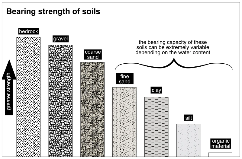
0203Bearing strength of soils
· p. 32
The illustration compares the relative bearing strengths of bedrock and several soil types using patterned bars of descending height. An upward arrow indicates greater strength, with bedrock highest, followed by gravel, coarse sand, fine sand, clay, silt, and organic material. A bracket spanning fine sand through organic material notes that their bearing capacity can be extremely variable depending on water content. No numerical capacities, footings, or foundation assemblies are shown.
 0204
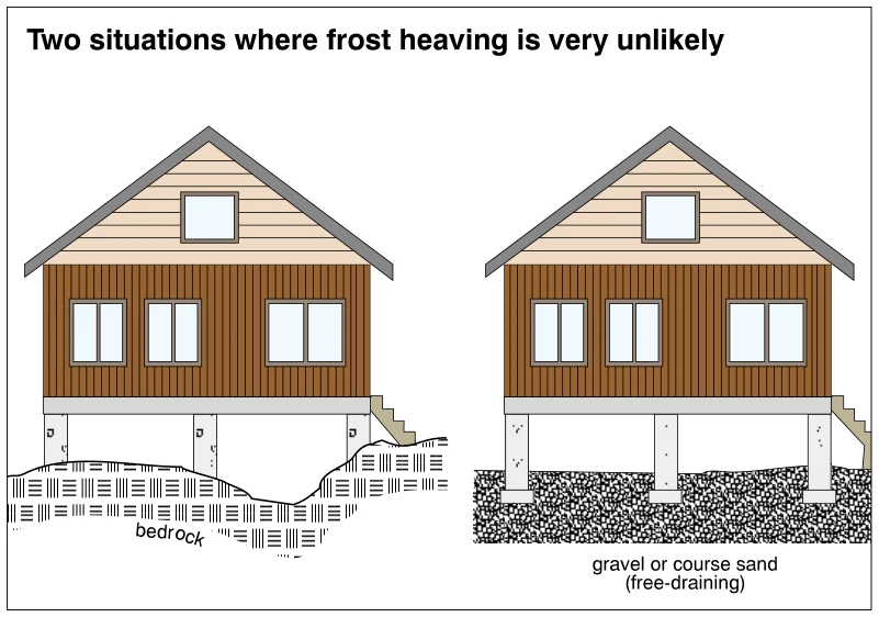
0204Two situations where frost heaving is very unlikely
· p. 32
The illustration shows two houses supported on foundation piers with different bearing conditions. On the left, the piers extend to an irregular bedrock surface. On the right, piers with widened footings bear in gravel or sand labeled as free-draining. Both conditions are presented as situations where frost heaving is very unlikely.
 0205
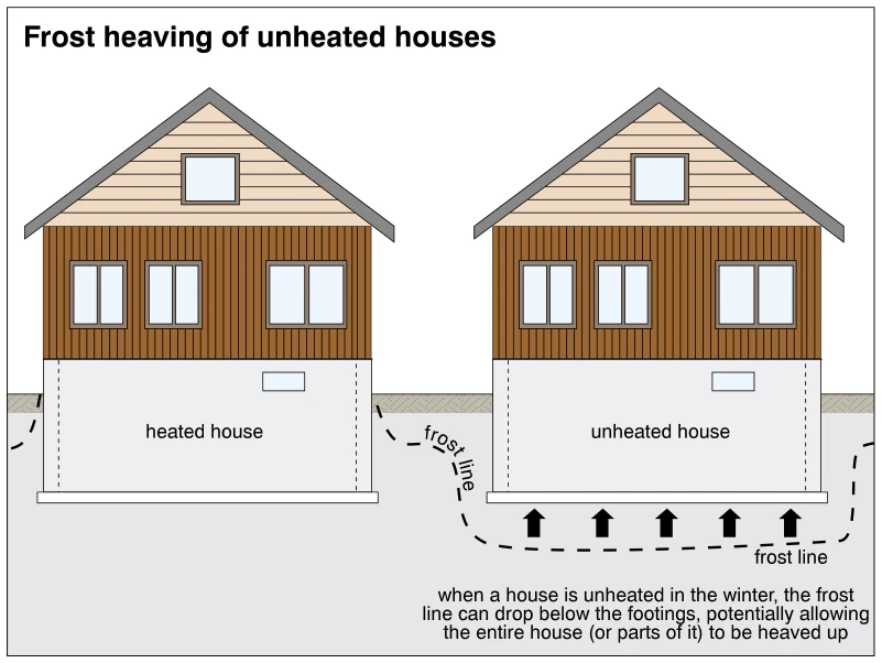
0205Frost heaving of unheated houses
· p. 32
The illustration compares the frost depth beneath a heated house and an unheated house, showing their foundation walls and continuous footings below grade. A dashed frost line remains above the footing level around the heated house but extends below the footings of the unheated house. Upward arrows beneath the unheated house indicate potential frost-heave forces acting on its foundation. The annotation explains that winter frost penetration below the footings can lift the entire house or portions of it.
 0206
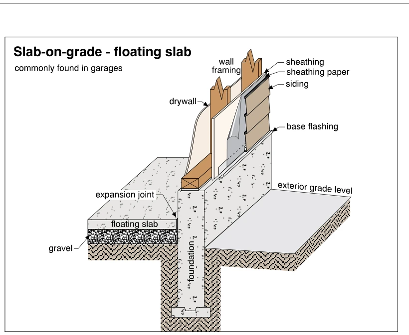
0206Slab-on-grade - floating slab
· p. 33
The cutaway depicts a floating concrete slab-on-grade beside a separate perimeter foundation wall and footing, an arrangement identified as commonly found in garages. The slab rests on a gravel layer and is separated from the foundation wall by an expansion joint. The foundation wall extends below the slab and exterior grade to a widened footing. Wood wall framing sits on the foundation, with interior drywall and exterior sheathing, sheathing paper, siding, and base flashing shown in cutaway. No damage or improper installation is indicated.
 0207
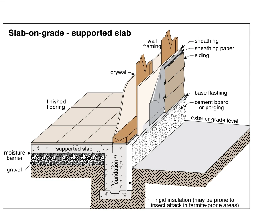
0207Slab-on-grade - supported slab
· p. 33
The cutaway shows a slab-on-grade floor with its perimeter supported by a foundation wall and footing. Finished flooring covers the slab, with a moisture barrier and gravel beneath it. A wood-framed exterior wall above the foundation includes interior drywall, sheathing, sheathing paper, and lap siding. Exterior rigid insulation extends down the foundation, with cement board or parging protecting its exposed upper portion and base flashing at the siding transition. The drawing marks the exterior grade level and cautions that rigid insulation may be prone to insect attack in termite-prone areas.
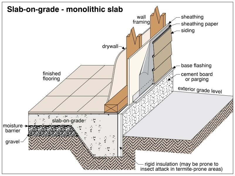 0208
0208Slab-on-grade - monolithic slab
· p. 33
The cutaway depicts a monolithic concrete slab-on-grade with a thickened perimeter forming the foundation beneath a framed exterior wall. Finished flooring covers the slab, with a moisture barrier and gravel beneath it. The wall includes wood framing, interior drywall, exterior sheathing, sheathing paper, and lap siding. Vertical rigid insulation covers the slab edge, with cement board or parging protecting the exposed exterior face and base flashing at the bottom of the siding. Exterior grade is below the floor level, and an annotation warns that rigid insulation may be prone to insect attack in termite-prone areas.
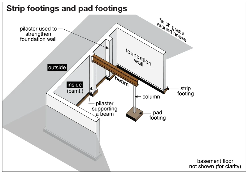 0209
0209Strip footings and pad footings
· p. 33
The cutaway illustration shows basement foundation walls supported on continuous strip footings, with finish grade indicated outside the house. An interior beam bears on a wall pilaster and is supported by a column resting on an isolated pad footing. Another pilaster is identified as strengthening the foundation wall. The basement floor is omitted for clarity, exposing the relationship between the walls, beam, column, and footings. No defects or improper practices are indicated.
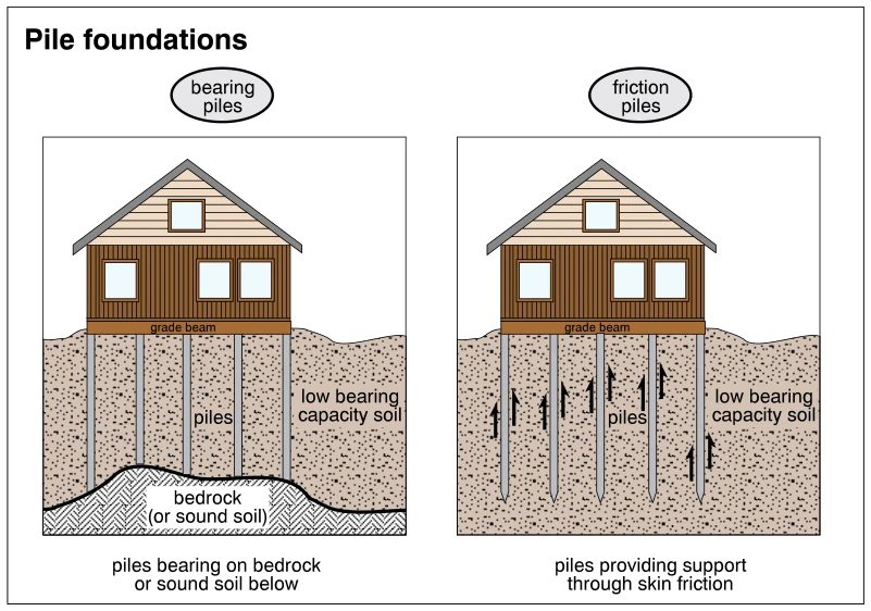 0210
0210Pile foundations
· p. 33
Two side-by-side sections illustrate houses supported on pile foundations beneath grade beams. On the left, bearing piles extend through low bearing capacity soil and terminate on bedrock or sound soil below. On the right, friction piles extend into low bearing capacity soil without a depicted bedrock bearing surface. Upward arrows along the friction pile shafts indicate support provided through skin friction. The illustration compares two foundation load-transfer mechanisms rather than correct and incorrect installation.
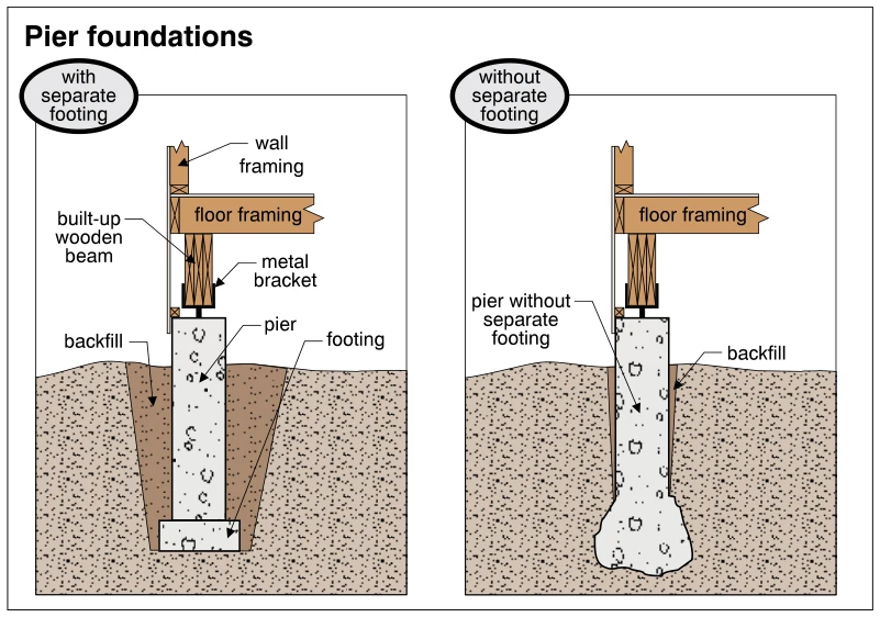 0211
0211Pier foundations
· p. 33
Two sectional diagrams show pier foundations supporting wood floor and wall framing through a built-up wooden beam and metal bracket. The left diagram shows a straight concrete pier bearing on a separate, wider rectangular footing below grade, with backfill around the assembly. The right diagram shows a concrete pier without a separate footing, widening into an irregular enlarged base below grade. Both arrangements illustrate foundation configurations rather than identified defects.
 0212
0212Brick foundation with masonry exterior walls
· p. 34
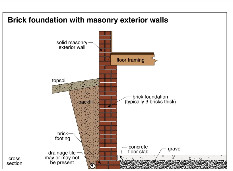
The illustration shows a cross section of a brick foundation supporting a solid masonry exterior wall and wood floor framing. The foundation is labeled as typically three bricks thick and widens at its base to form a brick footing. Exterior backfill lies against the foundation beneath a layer of topsoil. On the interior, a concrete floor slab rests on gravel alongside the footing. A drainage tile is shown near the exterior base of the footing, with a note that it may or may not be present.
 0213
0213Stone foundation with masonry exterior walls
· p. 34
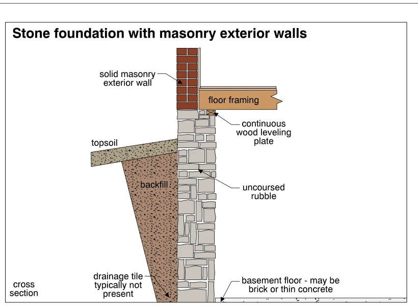
The cross section shows a solid masonry exterior wall supported on an uncoursed rubble stone foundation. Interior floor framing bears at the top of the foundation on a continuous wood leveling plate. Outside, backfill lies against the foundation beneath a layer of topsoil that slopes away from the wall. The basement floor meets the inside face of the foundation at its base and is identified as potentially brick or thin concrete. An annotation notes that drainage tile is typically not present.
 0214
0214Stone foundation wall with wood frame exterior walls
· p. 34
The cross section shows a wood-frame exterior wall and floor framing supported on a sill at the top of a stone foundation wall. Wood siding covers the exterior face of the wall framing. The foundation consists of irregular stones identified as uncoursed rubble, with backfill against its exterior and a layer of topsoil at grade. A basement floor meets the interior base of the foundation and is annotated as potentially brick or thin concrete. The drawing notes that drainage tile is typically not present.
 0215
0215Raft and mat foundations
· p. 34
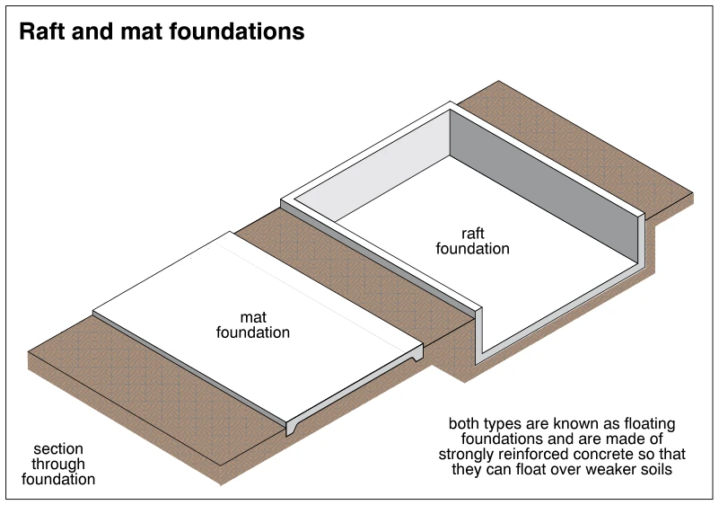
The illustration shows cutaway views of mat and raft foundations resting on soil. The mat foundation is depicted as a broad, flat concrete slab with locally thickened edges visible in section. The raft foundation has a broad concrete base connected to upright perimeter walls. An annotation identifies both as floating foundations made of strongly reinforced concrete to distribute support over weaker soils. No defects are depicted.
 0216
0216Preserved wood foundations
· p. 34
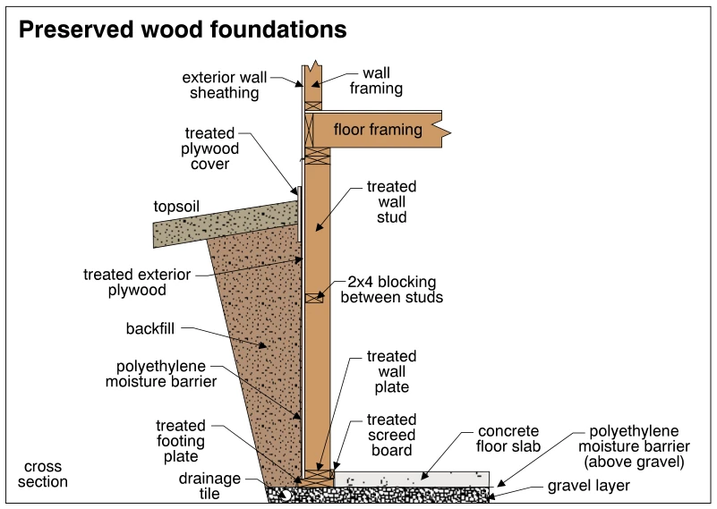
The cross section depicts a preserved wood foundation wall supporting floor framing and an above-grade framed wall. Treated wall studs, 2x4 blocking, and treated exterior plywood form the foundation wall, with a polyethylene moisture barrier on the backfill side and a treated plywood cover near grade. The wall rests on a treated wall plate and treated footing plate over a gravel layer. A concrete floor slab abuts a treated screed board on the interior, with a polyethylene moisture barrier above the gravel beneath the slab. Drainage tile is shown in the gravel at the exterior base of the foundation.
 0217
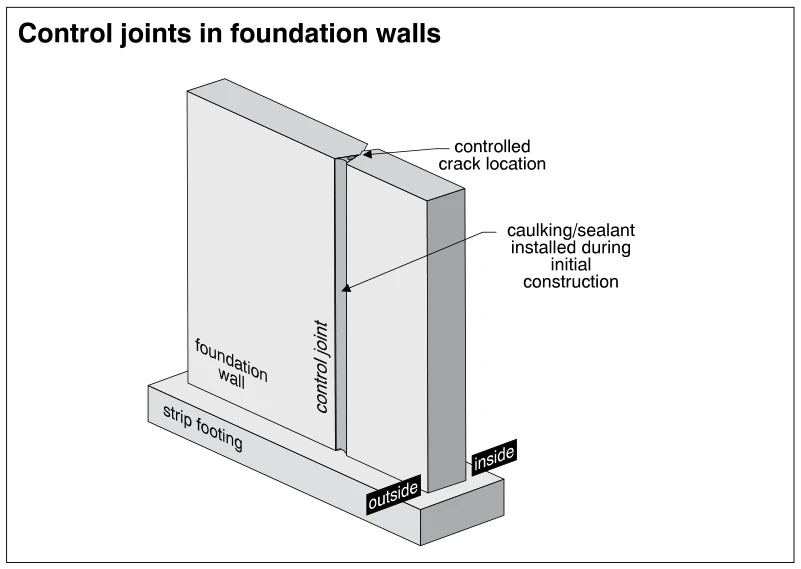
0217Control joints in foundation walls
· p. 34
The illustration shows a foundation wall supported on a continuous strip footing, with the inside and outside faces identified. A vertical control joint extends down the outside face of the wall to the footing. A detail at the top of the joint identifies the controlled crack location through the wall thickness. Caulking or sealant is shown at the exterior joint and is noted as being installed during initial construction.
Footings And Foundations ·Problemsp. 35
 0217.3
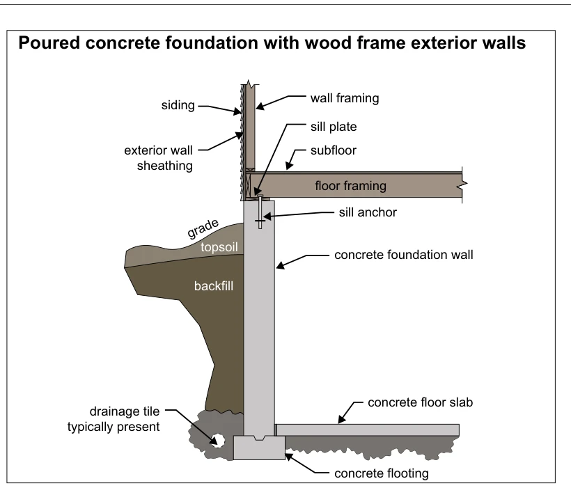
Poured concrete foundation with wood frame exterior walls
· p. 35
The illustration shows a section through a poured concrete foundation supporting wood-framed exterior walls and floor framing. A sill plate sits on the foundation wall and is secured by a sill anchor, with subfloor above the floor framing and sheathing and siding on the exterior wall. The foundation wall extends down to a wider concrete footing, beside which the interior concrete floor slab is shown. Exterior backfill and topsoil meet the wall below the wood framing, and a drainage tile is shown beside the footing. No specific defect is identified.
 0217.6
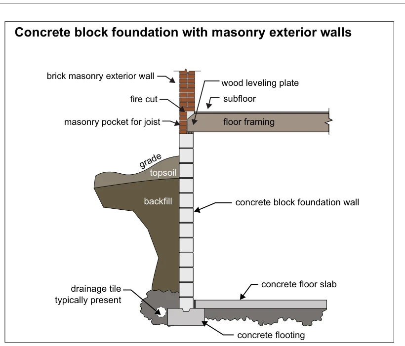
Concrete block foundation with masonry exterior walls
· p. 35
The illustration shows a cross-section of a concrete block foundation wall supporting a brick masonry exterior wall. Wood floor framing enters a masonry pocket, with a fire-cut joist end, a wood leveling plate beneath it, and subfloor above. The foundation wall bears on a widened concrete footing, with an interior concrete floor slab alongside its base. Exterior backfill and topsoil meet the wall below the floor framing, and drainage tile is shown beside the footing. The drawing identifies the assembly without explicitly marking any defects.
 0217.9
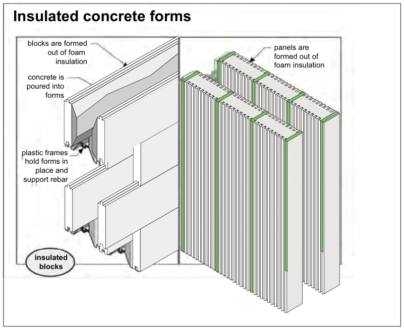
Insulated concrete forms
· p. 35
The illustration shows block and panel configurations of insulated concrete forms used for foundation walls. On the left, foam insulation blocks are stacked with staggered joints, creating a cavity into which concrete is poured. Plastic frames hold the forms in position and support reinforcing steel, as noted by the callout. On the right, paired ribbed foam panels form the two faces of a wall cavity. No defects or improper installation practices are depicted.
 0218
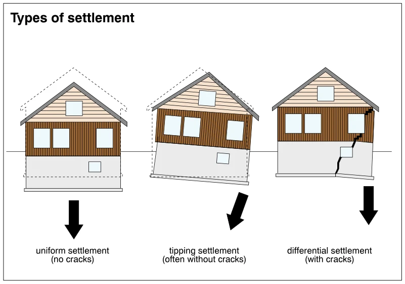
0218Types of settlement
· p. 35
Three house elevations illustrate uniform, tipping, and differential settlement of buildings and their foundations. The uniform-settlement example shows the house moving downward evenly without cracks, with dashed outlines indicating its earlier position. The tipping example shows the house and foundation tilting together, often without cracks. The differential-settlement example shows uneven movement with a prominent crack extending through the foundation and into the exterior wall near window openings. Large arrows beneath each house indicate the direction of movement.
 0219
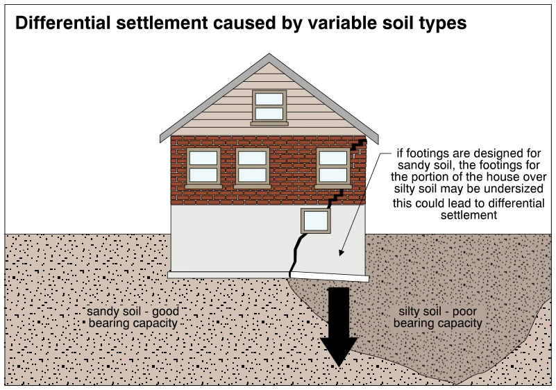
0219Differential settlement caused by variable soil types
· p. 35
The illustration shows a house with its foundation and footing bearing partly on sandy soil and partly on a pocket of silty soil. The sandy soil is identified as having good bearing capacity, while the silty soil has poor bearing capacity. The footing slopes downward on the silty-soil side, with a large downward arrow indicating settlement. Cracks extend through the foundation wall and brick wall above on that side of the house. The annotation explains that footings designed for sandy soil may be undersized where they bear on silty soil, leading to differential settlement.
 0220
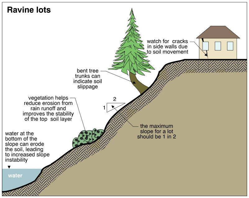
0220Ravine lots
· p. 35
The illustration shows a cross-section of a ravine lot with a house near the crest and water at the bottom of the slope. A bent tree trunk is identified as a possible indicator of soil slippage, and an arrow at the house advises watching for side-wall cracks caused by soil movement. Vegetation on the slope is shown helping reduce runoff erosion and stabilize the topsoil. Water at the toe of the slope is identified as a potential source of erosion and increased slope instability. A slope triangle indicates a maximum lot slope of one vertical to two horizontal.
 0221
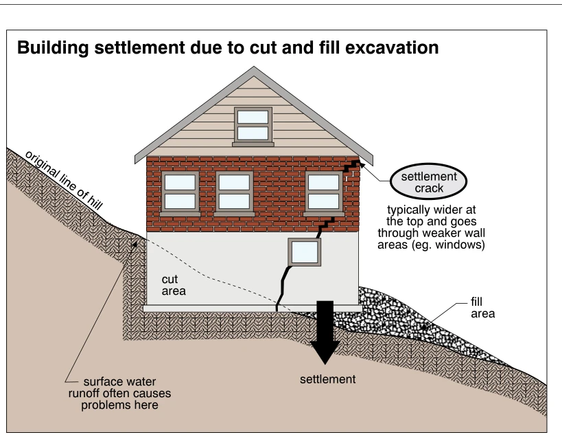
0221Building settlement due to cut and fill excavation
· p. 36
The illustration shows a house built on a hillside leveled by cutting into the uphill side and placing fill on the downhill side. A dashed line beneath the house indicates the original slope, with the foundation and footing spanning the cut and fill areas. A large downward arrow indicates settlement on the fill side. An irregular settlement crack extends through the foundation wall and brick wall near window openings; the annotation notes that such cracks are typically wider at the top and pass through weaker wall areas. Surface water runoff is also identified as a potential problem at the uphill side of the foundation.
 0222
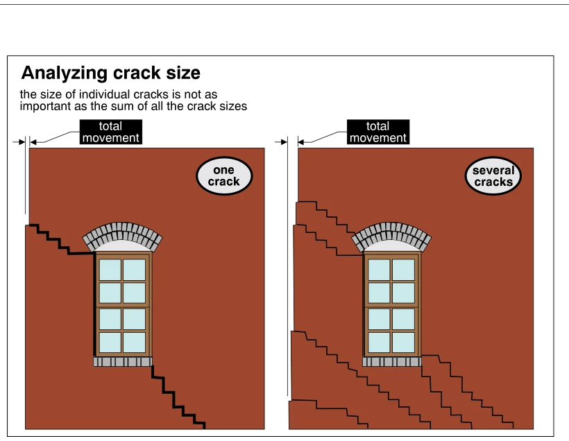
0222Analyzing crack size
· p. 36
Two masonry wall elevations with arched window openings compare movement concentrated in one large crack with movement distributed among several smaller cracks. The left wall has a wide stair-step crack extending from the wall edge to the window opening and continuing below the window to the base. The right wall shows several narrower stair-step cracks around and below the window. Dimension arrows at the upper left of each wall identify total movement. The illustration emphasizes that the sum of crack widths is more important for assessing overall movement than the width of an individual crack.
 0223
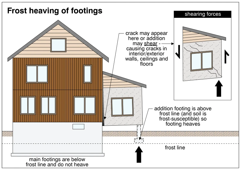
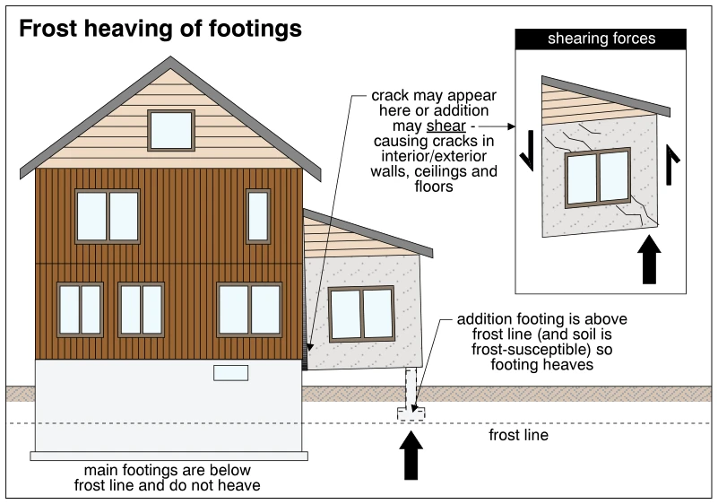
0223Frost heaving of footings
· p. 36
The illustration shows a house with a deep foundation and an attached addition supported on a shallow footing. The main house footings extend below the dashed frost line, while the addition footing lies above it in frost-susceptible soil. An upward arrow indicates frost heave beneath the addition footing, and a callout identifies potential cracking at the junction with the main house. An inset shows shearing forces and cracks around the addition's window, illustrating damage associated with differential movement.
 0224
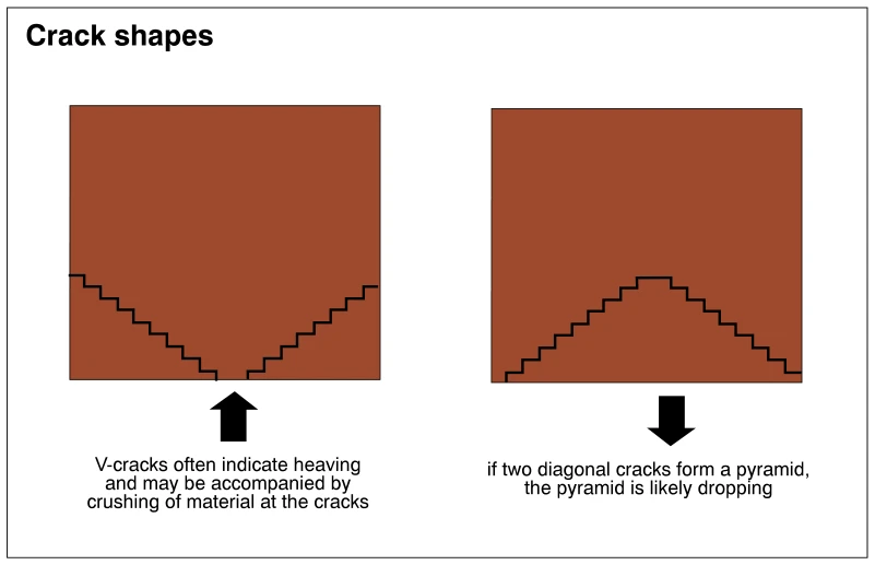
0224Crack shapes
· p. 36
Two schematic wall elevations illustrate stepped diagonal crack patterns associated with different directions of movement. On the left, cracks descend toward the bottom center to form a V, with an upward arrow indicating heaving; the annotation notes that material may be crushed at the cracks. On the right, two diagonal cracks rise toward the center to outline a pyramid-shaped lower section, with a downward arrow indicating that this section is likely dropping. The diagrams show crack geometry and movement direction without detailing wall construction or footings.
 0225
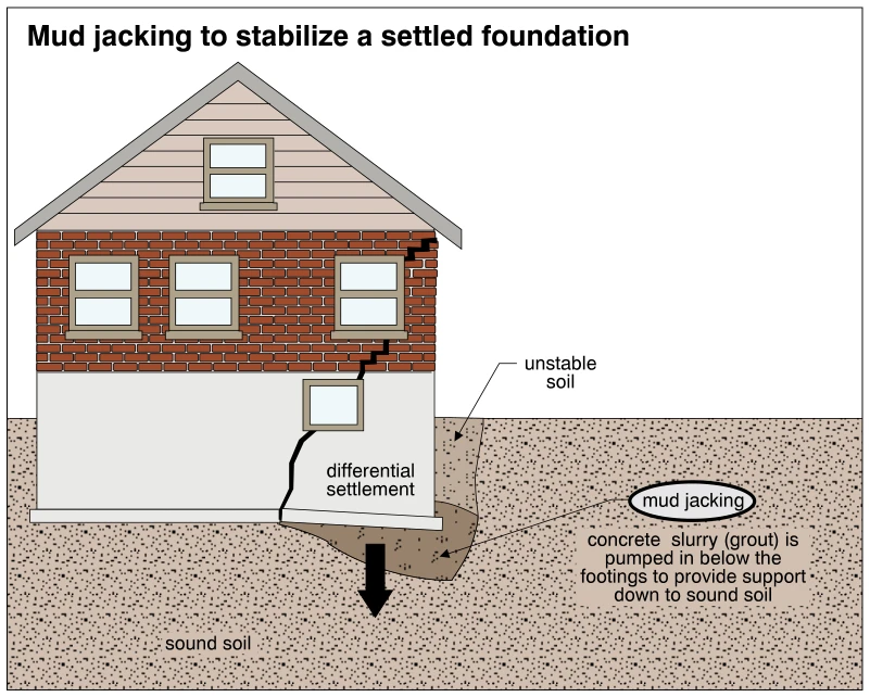
0225Mud jacking to stabilize a settled foundation
· p. 36
The illustration shows a house elevation with a cutaway of the soil beneath its foundation and footings. The right side has settled differentially over unstable soil, with cracking through the foundation wall and stair-step cracking in the brick wall above. A downward arrow emphasizes settlement beneath the affected footing. Mud jacking is illustrated as concrete slurry (grout) pumped below the footing to provide support down to sound soil.
 0226
0226Using a helical anchor to stabilize a settled foundation
· p. 36
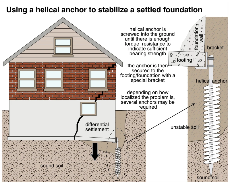
The illustration shows differential settlement at one side of a house, with a crack through the foundation wall and stepped cracking in the brick wall above. A helical anchor is installed beside the settled footing and extends through unstable soil into sound soil. An enlarged detail shows a bracket connecting the footing/foundation to the anchor shaft. Annotations explain that the anchor is screwed into the ground until torque resistance indicates sufficient bearing strength, then secured to the foundation with a special bracket. Several anchors may be needed depending on how localized the settlement is.
 0227
0227Using piles to stabilize a settled foundation
· p. 37
The illustration shows a house with differential settlement at one end of its foundation, indicated by a downward arrow and a sloping footing. Cracks extend through the foundation wall and the brick wall above, near window openings. A vertical pile passes through unstable soil to sound soil beneath the settled end. A reinforced concrete cap bridges between the pile and the house foundation to provide stabilizing support.
 0228
0228Using rods and channels to stabilize a settled house
· p. 37
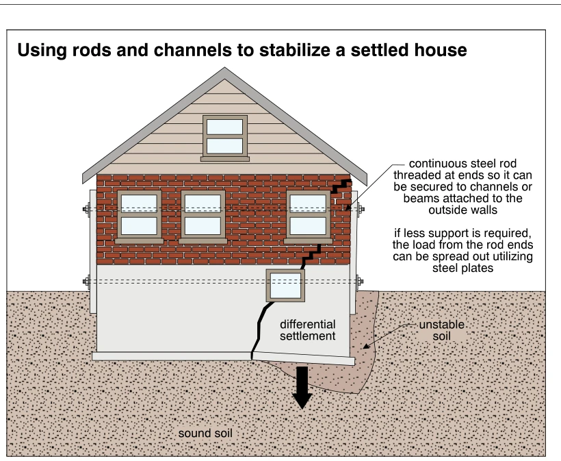
The illustration shows a brick house with a below-grade foundation and footing affected by differential settlement on the right side. A zone of unstable soil beneath that side contrasts with the surrounding sound soil, and a downward arrow indicates settlement. Large cracks extend through the foundation and brick wall, with the footing sloping downward toward the settled side. Horizontal continuous steel rods pass through the house and are secured at their threaded ends to exterior channels or beams. An annotation identifies steel plates as an alternative for distributing rod-end loads where less support is required.
 0229
0229Step footings on sloped lots
· p. 37
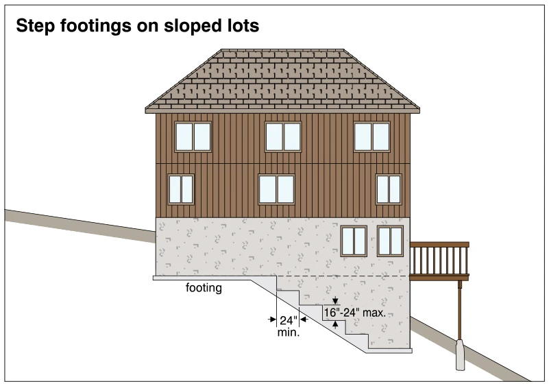
The illustration shows a house on a lot that slopes downward from left to right, exposing more of the foundation wall on the downhill side. The foundation and its supporting footing descend in a series of horizontal steps rather than following a continuous incline. Dimension arrows indicate a minimum horizontal step length of 24 inches and a maximum vertical step height of 16–24 inches. A small deck projects from the downhill side and is supported by a post on a separate concrete support.
 0230
0230Lowering basement floors - bench footing
· p. 37
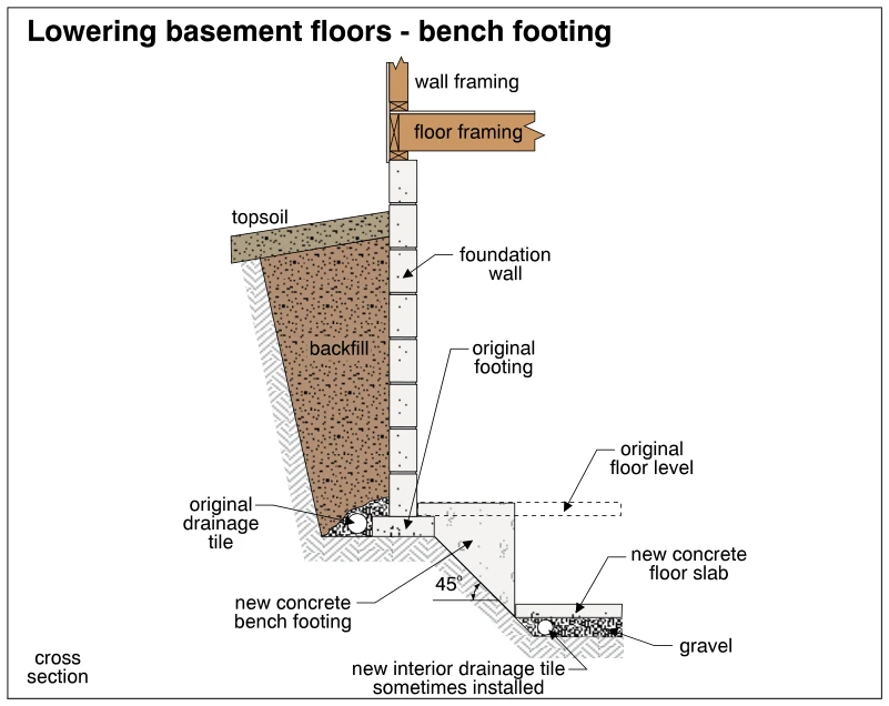
The cross section shows a basement floor lowered below the original foundation footing using a new concrete bench footing along the interior perimeter. The foundation wall and original footing remain in place, while the bench projects inward and extends down to the lowered floor level. A 45° angle is marked beside the sloping underside of the bench footing. The new concrete floor slab rests over gravel, with an optional interior drainage tile shown beneath its perimeter. Exterior backfill, topsoil, the original drainage tile, and wood wall and floor framing provide context for the assembly.
 0231
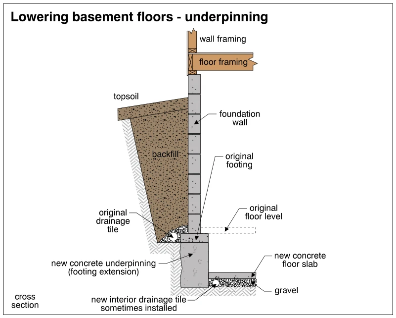
0231Lowering basement floors - underpinning
· p. 37
The cross section illustrates lowering a basement floor by extending the foundation support downward with concrete underpinning beneath the original footing. The existing foundation wall supports wood wall and floor framing, with topsoil and backfill on the exterior side. A dashed outline marks the original floor level above the new concrete floor slab. The lowered slab rests on gravel beside the underpinning, with an optional new interior drainage tile shown below its edge. The original exterior drainage tile remains beside the original footing.
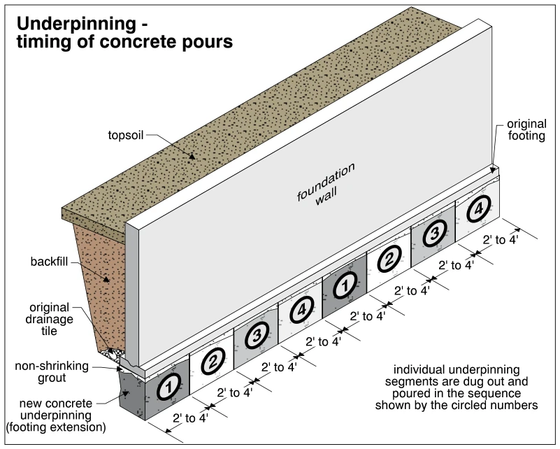 0232
0232Underpinning - timing of concrete pours
· p. 37
The illustration shows a foundation wall and original footing supported by new concrete underpinning segments. Each segment is labeled as 2 to 4 feet long, with circled numbers specifying the excavation and pouring sequence. The repeated sequence of 1 through 4 indicates that separated segments are completed in stages rather than excavating the entire footing at once. Non-shrinking grout is shown at the interface between the underpinning and the existing footing. A cutaway beside the wall identifies topsoil, backfill, and the original drainage tile.
 0233
0233Rotational settlement cracks
· p. 38
The illustration shows a two-story house with a gabled roof and a single-story shed-roof addition on its right side. Both structures have foundation walls and projecting footings shown below grade. The addition is tilted away from the main house, producing a separation at their junction that is wider at the top than at the bottom. A downward arrow identifies the addition as settling relative to the house, illustrating differential settlement with rotation.
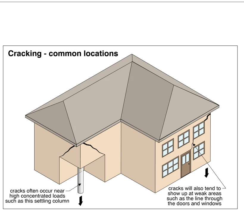 0234
0234Cracking - common locations
· p. 38
The illustration shows a two-story house with a hip roof and cracks at two common locations in its walls. A cutaway at the left exposes a supporting column beneath a wall corner, with cracks extending across the walls above the column. A downward arrow indicates settlement of this concentrated support. On the right elevation, a crack follows a weak line through the door and window openings, with another downward arrow indicating movement.
 0235
0235Frost heaving of footings
· p. 38
The illustration shows a house with deep main foundation footings and an attached addition supported on a shallow footing. A dashed frost line passes above the main footings but below the addition footing. An upward arrow indicates frost heaving beneath the shallow footing in frost-susceptible soil. The resulting differential movement can cause cracking at the house-addition junction or shear distortion of the addition. An inset depicts opposing vertical forces and cracks around the addition's window.
 0236
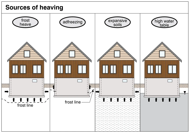
0236Sources of heaving
· p. 38
Four side-by-side house and foundation diagrams illustrate sources of foundation heaving: frost heave, adfreezing, expansive soils, and a high water table. The frost-heave panel shows a frost line beneath the footing, with arrows indicating upward pressure below and inward pressure at the foundation sides. The adfreezing panel shows upward forces along the outside faces of the foundation and identifies the frost line. The expansive-soils panel shows surrounding soil exerting upward pressure beneath the footing and inward pressure at the sides. The high-water-table panel shows a water level above the footing and arrows indicating upward pressure beneath the foundation.
 0237
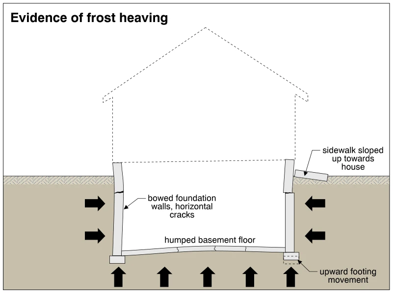
0237Evidence of frost heaving
· p. 38
A cross-section of a house foundation illustrates damage associated with frost heaving in the surrounding soil. Large horizontal arrows show inward pressure against the foundation walls, which are bowed and horizontally cracked or displaced. Upward arrows beneath the footings and basement floor indicate lifting, with the basement floor shown humped and cracked. A sidewalk beside the house slopes upward toward the foundation, and a dashed outline beneath the right footing indicates its upward movement.
 0238
0238Exterior basement stairwell
· p. 38
The illustration shows a side-view cross section of an exterior stairwell descending to a basement door, with a perspective inset locating the stairwell beside a house. Railings protect the stairwell opening, and a sloping handrail follows the stairs. Annotations call for a 4- to 6-inch door threshold, a drain at the bottom landing, and soil sloping away from the stairwell to reduce water pressure on its side walls. The side wall is identified for inspection for bowing or cracks. The foundation section indicates the old footing location and a lowered footing extending below and to either side of the stairwell.
 0239
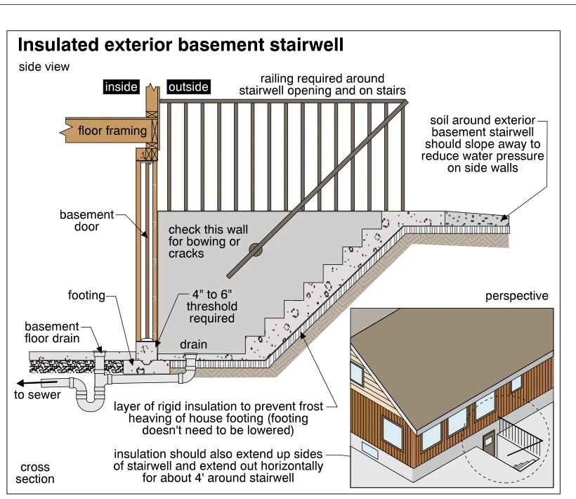
0239Insulated exterior basement stairwell
· p. 39
The illustration shows a section through an insulated exterior basement stairwell, with a perspective inset locating the stairwell beside a house. Concrete stairs descend to a drained landing outside the basement door, where a 4-inch to 6-inch threshold is specified. Rigid insulation runs beneath the stairs and landing to protect the house footing from frost heaving; annotations also call for insulation up the stairwell sides and extending horizontally about 4 feet around it. Railings surround the opening and follow the stairs, while adjacent soil is directed to slope away to reduce water pressure on the side walls. The drawing identifies the stairwell wall as a location to check for bowing or cracks and shows the drainage connection toward the sewer.
 0240
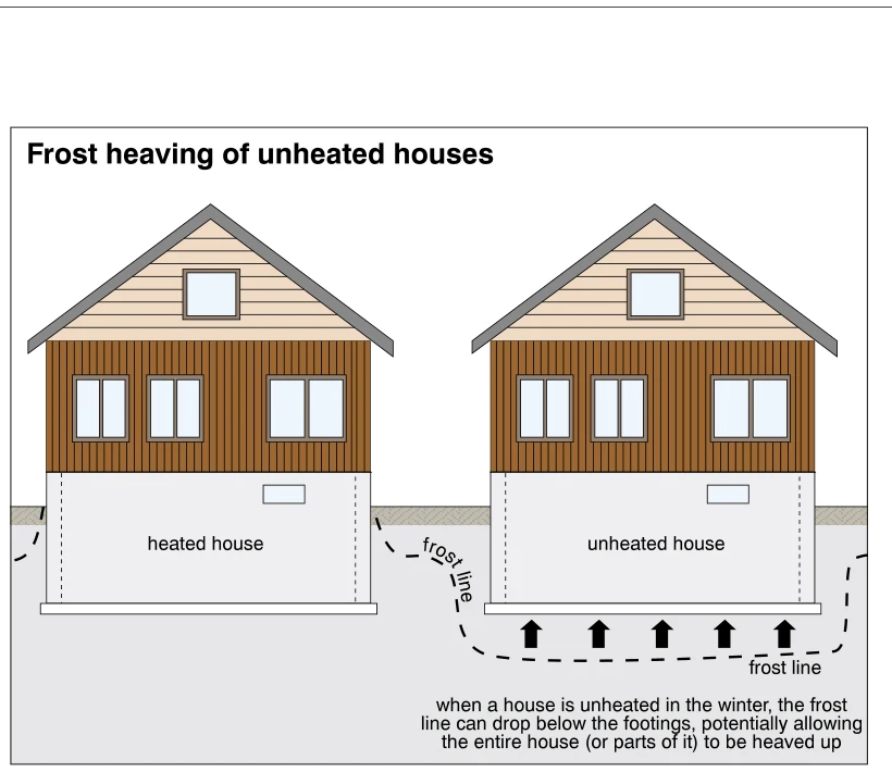
0240Frost heaving of unheated houses
· p. 39
The illustration compares frost penetration around the foundations and footings of a heated house and an unheated house. A dashed frost line remains above the footing level around the heated house but extends beneath the footings of the unheated house. Upward arrows beneath the unheated house indicate potential frost-heave forces on its foundation. The annotation explains that winter freezing beneath the footings can lift the entire house or portions of it.
 0241
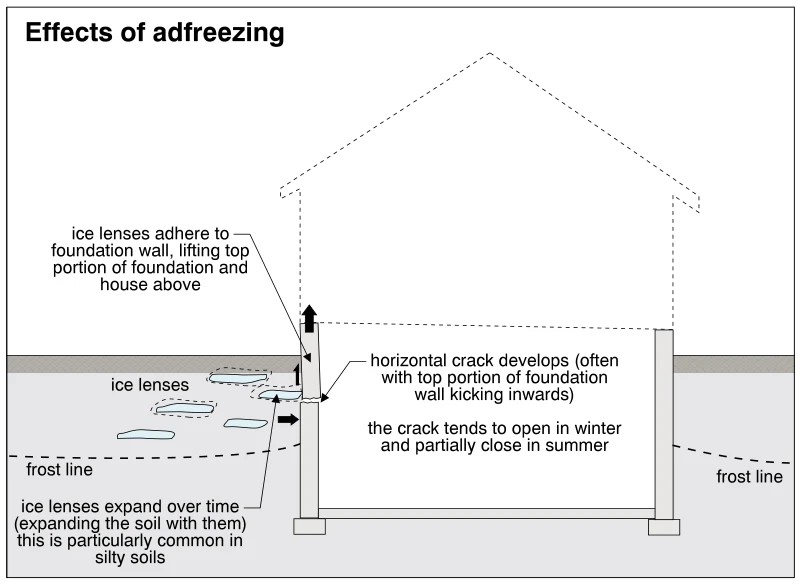
0241Effects of adfreezing
· p. 39
The illustration shows a house foundation in section, with foundation walls supported on footings and a floor slab between them. Ice lenses in the soil above the frost line adhere to the exterior of the left foundation wall. Arrows show upward lifting of the upper wall and house, along with inward movement at a horizontal wall crack. The annotations explain that expanding ice lenses enlarge the surrounding soil, particularly in silty soils, and that the crack tends to open in winter and partially close in summer.
 0242
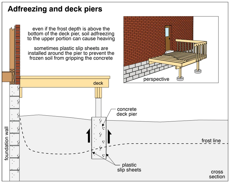
0242Adfreezing and deck piers
· p. 39
The illustration shows a deck attached to a house and supported at its outer edge by posts on concrete piers, with both perspective and cross-section views. In the cross section, the concrete deck pier extends below the dashed frost line, but upward arrows indicate heaving caused by frozen soil gripping the upper portion of the pier. The annotation explains that extending the pier below frost depth does not by itself prevent adfreezing-related movement. Plastic slip sheets around the pier are identified as a means of preventing frozen soil from gripping the concrete.
 0243
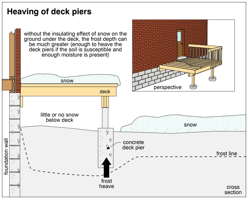
0243Heaving of deck piers
· p. 39
The illustration shows a deck attached to a house and supported at its outer edge by posts on concrete piers, with a perspective inset and a larger cross section. Snow covers the deck and adjacent ground, but little or no snow lies beneath the deck. The dashed frost line extends deeper beneath the uninsulated deck area than beneath the snow-covered ground and passes below the bottom of the illustrated pier. An upward arrow indicates frost heave acting on the pier; the annotation explains that susceptible soil and sufficient moisture can allow this deeper freezing to heave deck piers.
 0244
0244Foundation movement associated with horizontal cracks
· p. 39
Two adjoining foundation walls are shown on continuous footings, with horizontal cracks and inward deformation. Arrows indicate lateral thrust acting from outside toward the inside of the foundation. Labels identify bulging, bowing, and leaning, while dashed reference lines illustrate displacement of the walls. The cracks change direction or diminish near the corner, where the adjoining walls provide buttressing.
 0245
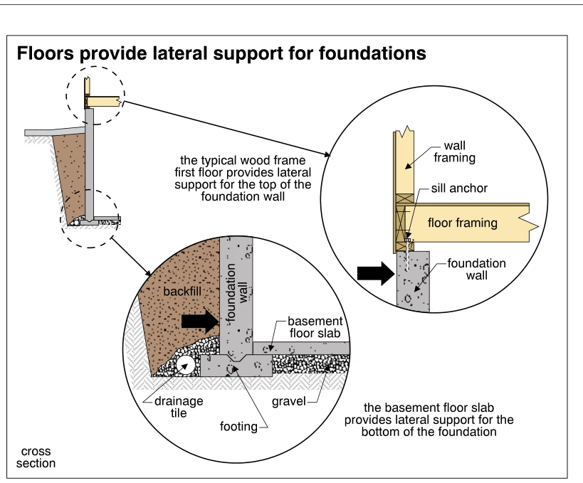
0245Floors provide lateral support for foundations
· p. 40
A foundation cross section includes enlarged details of the top and bottom of the foundation wall. At the top, wood wall and floor framing bear on the foundation, with a sill anchor securing the connection; the first-floor framing provides lateral support for the wall. At the bottom, the basement concrete floor slab abuts the foundation wall above the footing and provides lateral support at its base. Exterior backfill and inward-pointing arrows illustrate lateral pressure against the foundation. Gravel and drainage tile are shown beside the footing, with gravel also beneath the basement slab.
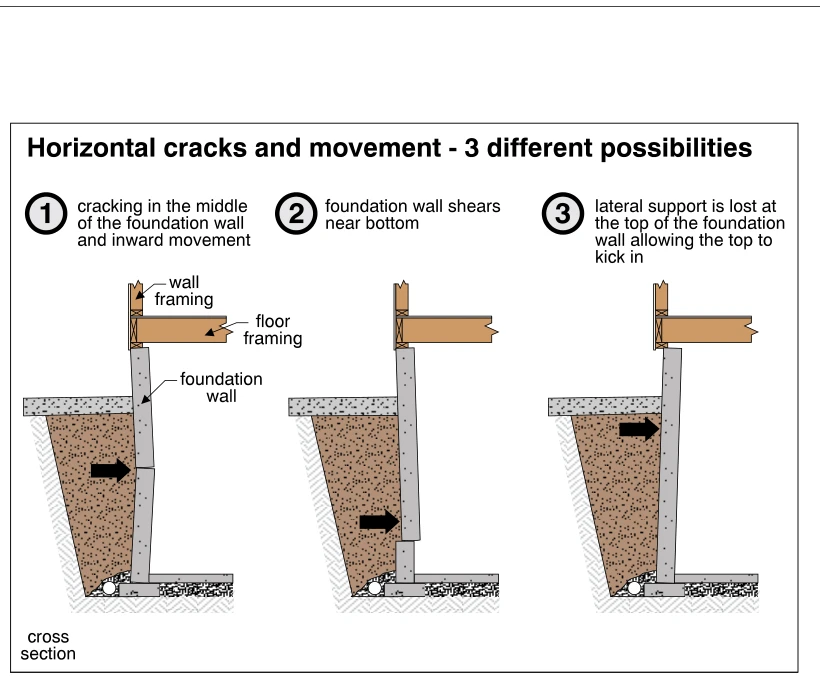 0246
0246Horizontal cracks and movement - 3 different possibilities
· p. 40
Three cross sections illustrate different patterns of inward foundation wall movement beside exterior soil backfill. The first shows a horizontal crack near midheight, with the wall bending inward at the crack. The second shows shearing near the bottom, with the upper wall displaced inward relative to its base. The third shows the top of the wall moving inward after loss of lateral support at the framing connection. Arrows indicate inward loading or movement, and each section includes framing above, a footing below, and a drain pipe beside the footing.
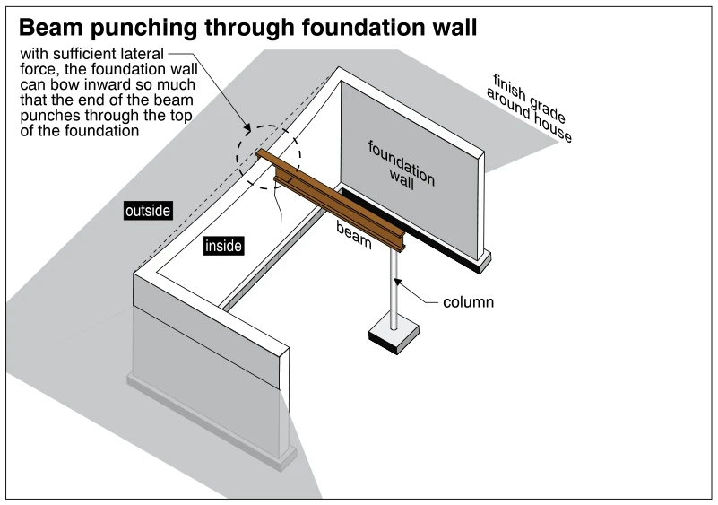 0247
0247Beam punching through foundation wall
· p. 40
The illustration shows a partial foundation enclosure with perimeter footings and a beam supported by a foundation wall at one end and an interior column on a pad footing. Surrounding finish grade is shown outside the walls. A dashed outline indicates inward displacement of the foundation wall, and a dashed circle highlights the beam end projecting through the top of the wall. Cracking is drawn below the beam bearing location. The annotation explains that sufficient lateral force can bow the wall inward until the beam punches through it.
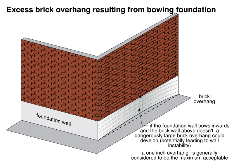 0248
0248Excess brick overhang resulting from bowing foundation
· p. 40
The illustration shows two brick walls meeting at a corner above foundation walls supported on a projecting footing. Along one side, the foundation wall bows inward while the brick wall above remains straight, creating excessive brick overhang. A dashed reference line along the base helps illustrate the foundation's inward displacement. The annotation identifies reduced support and potential wall instability, and states that a one inch overhang is generally considered the maximum acceptable.
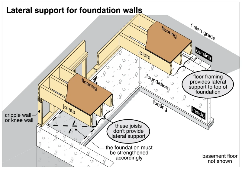 0249
0249Lateral support for foundation walls
· p. 40
The cutaway illustration compares foundation-wall lateral support with floor framing seated at the foundation top versus framing raised on a cripple wall or knee wall. On the right, the joists and flooring provide lateral support to the top of the foundation. On the left, a short wood-framed wall separates the floor framing from the foundation, and the annotation states that these joists do not provide lateral support. The foundation in this arrangement must be strengthened accordingly. Concrete foundation walls and footings are shown relative to the exterior finish grade, with the basement floor omitted.
 0250
0250Vertical foundation cracks
· p. 40
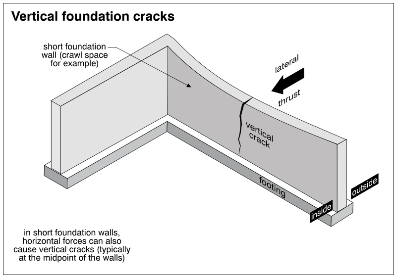
The illustration shows two short foundation walls meeting at a corner and supported on continuous footings. An arrow indicates lateral thrust acting from the outside toward the inside of one wall. That wall is depicted bowing inward, with a vertical crack near its midpoint extending downward from the top. The annotations explain that horizontal forces can cause vertical cracks in short foundation walls, such as those enclosing a crawl space.
 0251
0251Determining height of backfill
· p. 41
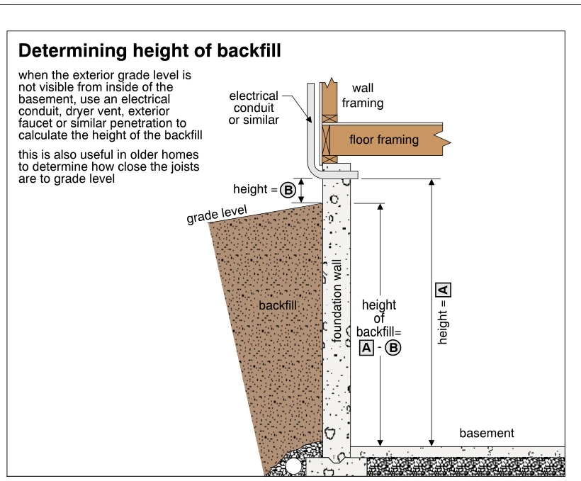
The illustration shows a section through a basement foundation wall and footing, with exterior backfill and wood wall and floor framing above. An electrical conduit or similar penetration through the top of the foundation provides a reference elevation visible from both sides. Dimension A runs from the basement floor level to this reference, while dimension B measures the reference height above exterior grade. Subtracting B from A determines the backfill height relative to the basement floor. The notes explain that this method is useful when exterior grade cannot be seen from the basement and for assessing how close floor joists are to grade.
 0252
0252How driveways can contribute to foundation cracking
· p. 41
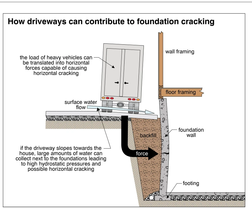
The illustration shows a heavy vehicle on a driveway beside a house foundation in cross-section. The foundation wall supports floor and wall framing and bears on a footing, with backfill against its exterior face. A large arrow illustrates vehicle loads being translated into lateral pressure through the backfill, and a horizontal crack is shown in the foundation wall. The driveway slopes toward the house, with an arrow showing surface water flowing toward the foundation. An annotation explains that water collecting beside the foundation can produce high hydrostatic pressure and possible horizontal cracking.
 0253
0253Foundation cracks related to tree roots
· p. 41
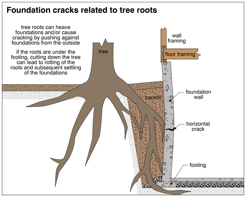
The cross-section depicts a tree next to a foundation wall supporting floor and wall framing. Tree roots extend through the exterior backfill, against the foundation wall, and beneath its footing. A horizontal crack is shown in the wall where a root presses against its exterior face. The annotations explain that roots can heave foundations or crack them by pushing from outside. They also warn that cutting down a tree with roots beneath the footing can lead to root decay and subsequent foundation settlement.
 0254
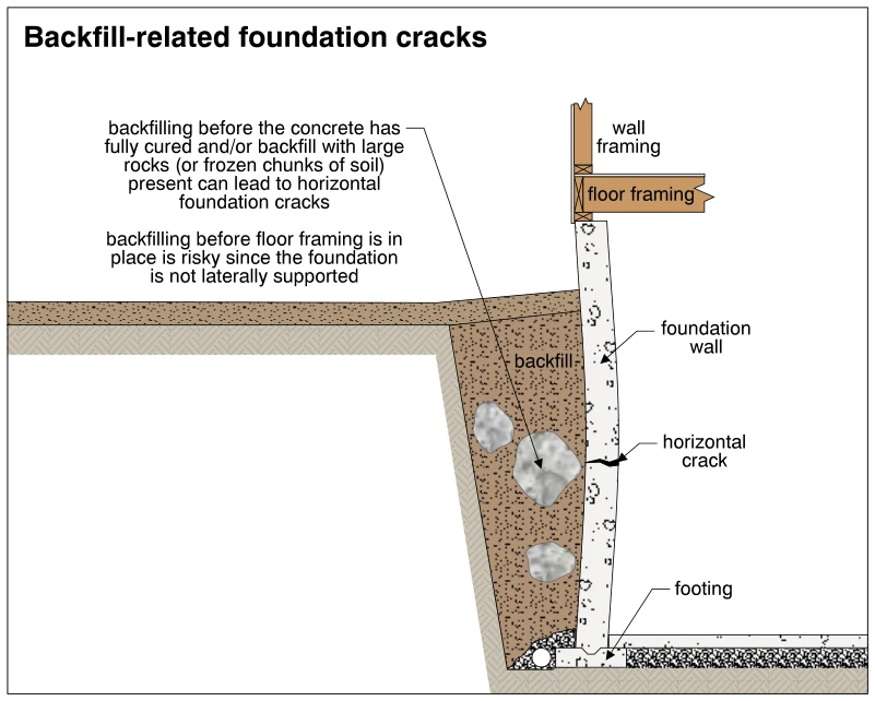
0254Backfill-related foundation cracks
· p. 41
The cross-section shows a concrete foundation wall on a footing, with soil backfill against its exterior and wood floor and wall framing above. Large rocks are embedded in the backfill beside the wall. The foundation wall is bowed inward and has a horizontal crack near mid-height. Annotations identify premature backfilling before concrete has fully cured and backfill containing large rocks or frozen soil chunks as potential causes of horizontal cracking. The drawing also warns that backfilling before floor framing is installed leaves the foundation without lateral support.
 0255
0255Basement floors provide lateral support
· p. 41
A basement foundation cross section is enlarged into two details comparing keyed and unkeyed foundation-wall connections to a footing. Horizontal arrows show backfill pressure pushing inward against the foundation wall. In both details, a basement floor slab abuts the inside face of the wall and provides lateral restraint at its base. The keyed detail shows the wall engaging a recess in the footing to resist sliding under horizontal pressure. Exterior drainage tile and gravel beneath the slab are also shown.
 0256
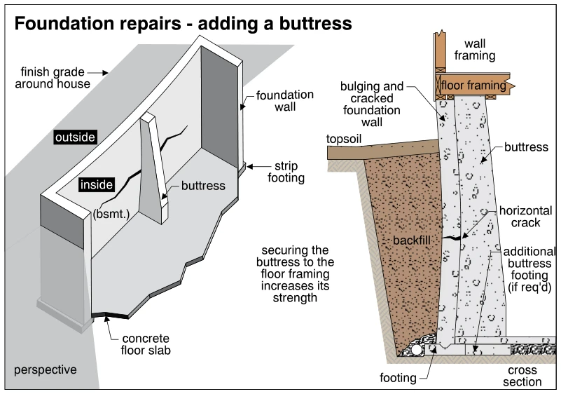
0256Foundation repairs - adding a buttress
· p. 41
Perspective and cross-section views illustrate adding an interior buttress to reinforce a bulging and cracked basement foundation wall. The perspective shows the buttress projecting inward from the wall beside the concrete floor slab, with the foundation supported on a strip footing. The cross section shows exterior topsoil and backfill against the damaged wall and a tapered buttress extending up to the floor framing on the interior. A horizontal crack is identified in the foundation wall, and an additional buttress footing is indicated if required. An annotation states that securing the buttress to the floor framing increases its strength.
 0257
0257Foundation repairs - adding a pilaster
· p. 42
Perspective and cross-section views depict adding an interior masonry pilaster to reinforce a bulging and cracked basement foundation wall. The perspective shows the pilaster against the wall above the concrete floor slab, with the foundation supported on a strip footing. The cross section shows exterior topsoil and backfill against the bowed wall, a horizontal crack, and the pilaster extending up to the floor framing. An additional footing beneath the pilaster is indicated if required. Notes recommend filling the pilaster block cores with concrete and reinforcement and securing the pilaster to the floor framing to increase its strength.
 0258
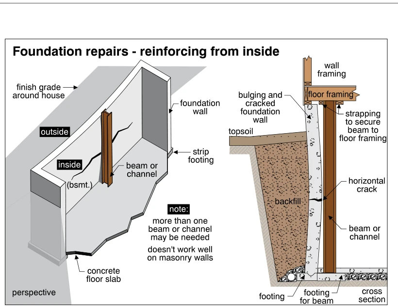
0258Foundation repairs - reinforcing from inside
· p. 42
Perspective and cross-section views illustrate reinforcing a bulging, cracked foundation wall from the basement side with a vertical beam or channel. The reinforcement is placed against the inside face of the wall, supported on a footing for the beam, and secured to the floor framing above with strapping. The cross section shows exterior topsoil and backfill against the wall, along with a horizontal crack through the wall. The perspective shows the foundation wall, strip footing, and concrete floor slab. Notes state that more than one beam or channel may be needed and that this repair does not work well on masonry walls.
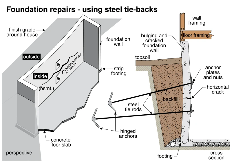 0259
0259Foundation repairs - using steel tie-backs
· p. 42
The illustration shows perspective and cross-section views of a foundation wall repaired with steel tie-backs. The wall has a horizontal crack and is shown bulging inward in cross section. Steel tie rods extend from anchor plates and nuts on the basement side of the wall, through the exterior backfill, to hinged anchors in the soil beyond. The drawings also show the foundation footing, basement concrete floor slab, exterior grade, and wood floor and wall framing above the foundation.
 0260
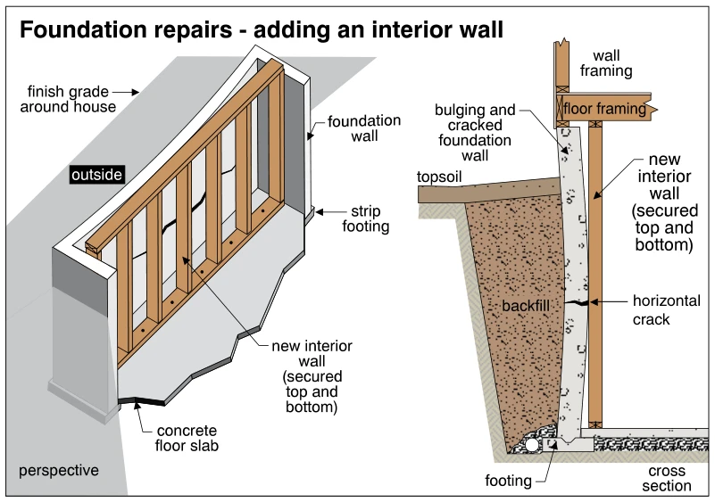
0260Foundation repairs - adding an interior wall
· p. 42
Perspective and cross-section views depict a foundation repair using a new interior wood-framed wall. The new wall stands immediately inside the existing foundation wall and is secured at its top and bottom. The cross section shows the foundation wall bulging inward and developing a horizontal crack, with backfill and topsoil on the exterior. The interior wall extends from the foundation base to the floor framing above, providing restraint against inward movement. The perspective view also identifies the strip footing and concrete floor slab.
 0261
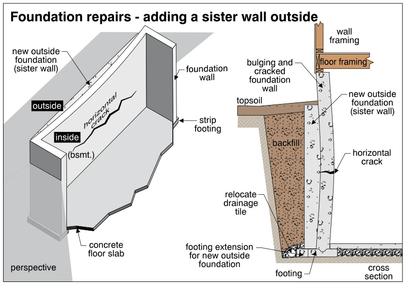
0261Foundation repairs - adding a sister wall outside
· p. 42
The illustration presents perspective and cross-section views of a foundation repair using a new exterior sister wall alongside an existing foundation wall. The existing wall is shown bulging inward and developing a horizontal crack. The new outside wall bears on a footing extension next to the existing footing, with backfill and topsoil on its exterior side. The cross section calls for relocating the drainage tile beside the extended footing. Wall and floor framing remain above the existing foundation, and a concrete basement floor slab is shown on the interior.
 0262
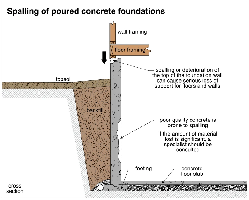
0262Spalling of poured concrete foundations
· p. 42
The cross section shows a poured concrete foundation wall on a footing supporting wood wall and floor framing. Topsoil and backfill lie against the exterior, while a concrete floor slab meets the wall near its base on the interior. Spalling is depicted at the top of the wall beneath the framing and along its interior face. The annotations warn that deterioration at the wall top can seriously reduce support for floors and walls, and that poor-quality concrete is prone to spalling. Consultation with a specialist is recommended when material loss is significant.
 0263
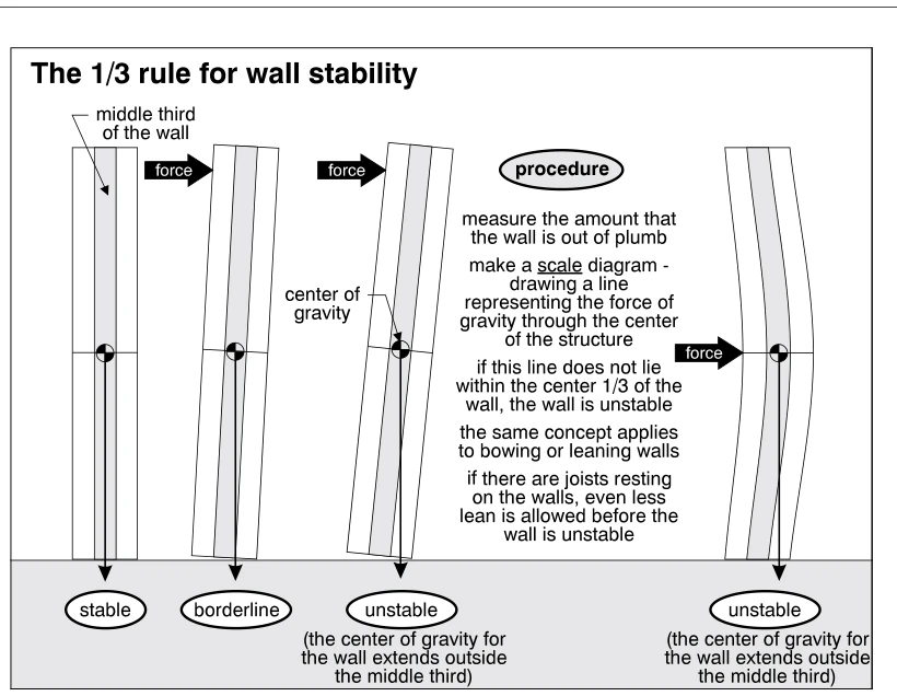
0263The 1/3 rule for wall stability
· p. 43
Four wall profiles illustrate the one-third rule for wall stability, comparing a plumb wall, two increasingly leaning walls, and a bowed wall. Each profile marks the wall's middle third, its center of gravity, and a vertical gravity line extending to the base. The plumb wall is labeled stable, the slightly leaning wall borderline, and the more severely leaning and bowed walls unstable because their gravity lines extend outside the middle third at the base. Horizontal arrows indicate forces acting on the displaced walls. The procedure instructs the reader to measure the out-of-plumb displacement and make a scale diagram, and notes that walls supporting joists allow even less lean before becoming unstable.
 0264
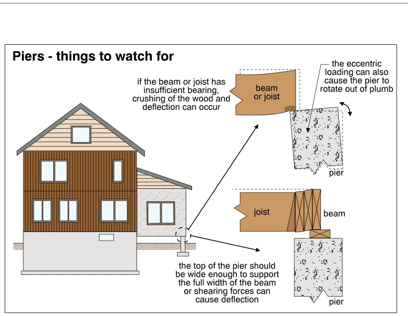
0264Piers - things to watch for
· p. 43
The illustration shows a house with a side addition supported at its outer edge by a pier and footing, with two enlarged views of wood framing bearing on piers. The upper detail shows a beam or joist with insufficient bearing on the edge of a concrete pier; the annotation warns of wood crushing and deflection. Eccentric loading is also shown causing the pier to rotate out of plumb. The lower detail shows joists meeting a built-up beam supported over a pier and warns that the pier top must support the beam's full width to avoid deflection from shearing forces.
 0265
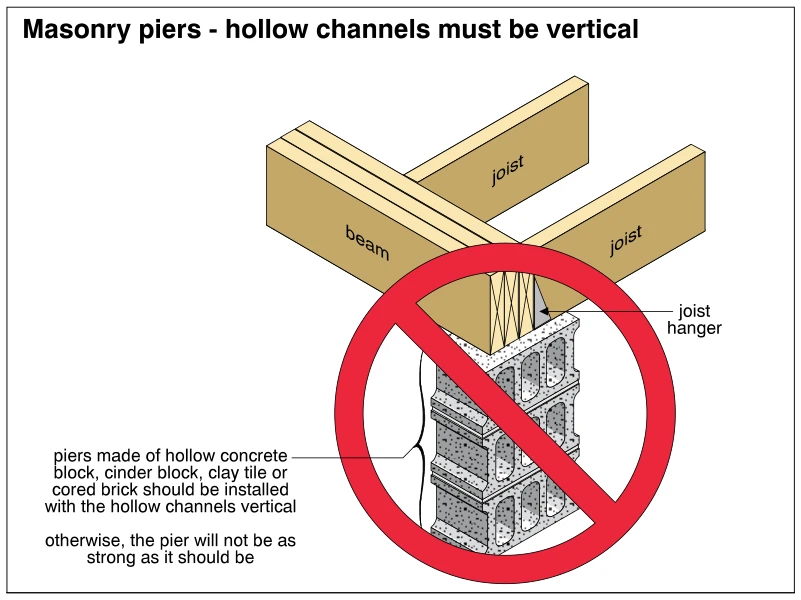
0265Masonry piers - hollow channels must be vertical
· p. 43
The illustration shows a built-up wood beam supported by a hollow masonry pier, with wood joists attached using joist hangers. The pier units are laid with their hollow channels horizontal, exposing the openings on the side of the pier. A red prohibition symbol identifies this orientation as incorrect. The annotation states that hollow concrete block, cinder block, clay tile, or cored brick piers must have their hollow channels vertical; otherwise, the pier will not have its intended strength.
 0266
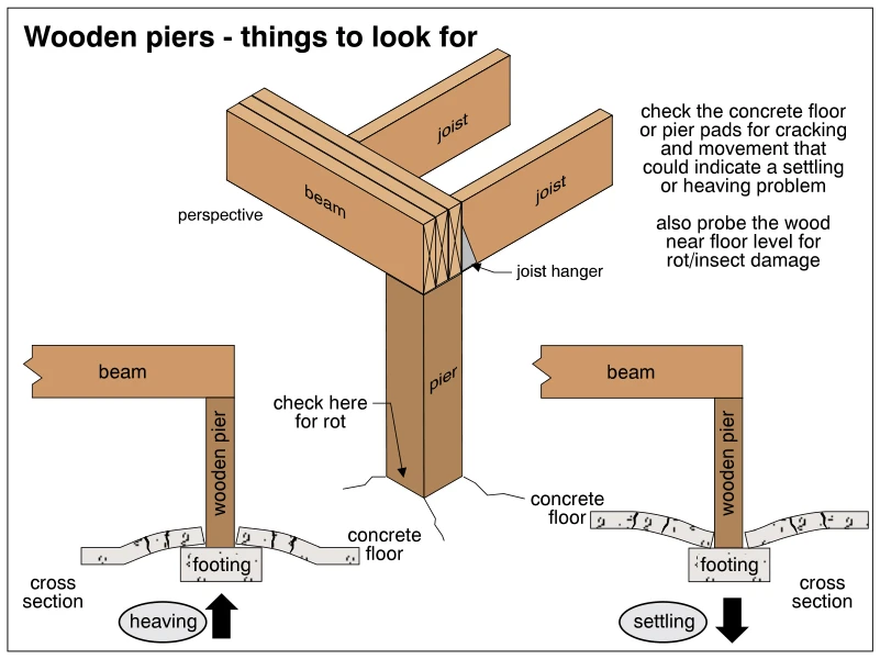
0266Wooden piers - things to look for
· p. 43
The perspective drawing shows a wooden pier supporting a built-up wood beam, with floor joists attached at the beam and a labeled joist hanger. Cracks are illustrated in the concrete floor around the pier, and an arrow identifies the base of the wood as a location to check for rot. Annotations advise checking the concrete floor or pier pads for cracking and movement and probing the wood near floor level for rot or insect damage. Two cross sections show a pier bearing on a footing: one illustrates upward heaving and the other downward settling, with corresponding distortion and cracking of the surrounding concrete floor.
 0267
0267Pilaster pulling away from wall
· p. 43
The cross section shows a bulging foundation wall with a horizontal crack, exterior backfill, and wood wall and floor framing above. A retrofit masonry pilaster on the interior side is pulling away from the foundation wall. Annotations identify poor installation, continued foundation wall leaning or bowing, and an inadequately sized or missing footing as possible causes. A plumb bob beside the pilaster illustrates checking whether it is plumb; the annotation also suggests using a mason's level.
 0268
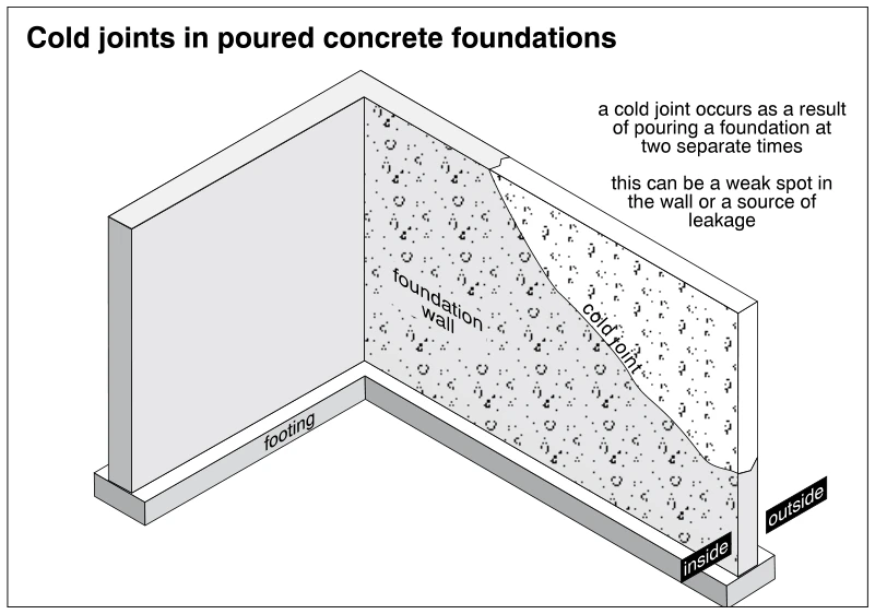
0268Cold joints in poured concrete foundations
· p. 43
The illustration shows two poured concrete foundation walls meeting at a corner and resting on continuous footings. An irregular cold joint runs diagonally down one wall, separating concrete placed at two separate times. The annotation identifies this joint as a potential weak spot in the foundation wall and a possible source of leakage. Labels indicate the inside and outside faces of the wall.
Floors ·Introductionp. 44
 0269
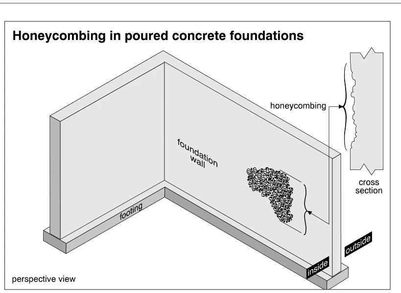
0269Honeycombing in poured concrete foundations
· p. 44
The illustration shows a perspective view of two poured concrete foundation walls meeting at a corner and supported on continuous footings. A localized honeycombed area on the inside face of one wall exposes coarse aggregate and voids within the concrete. Brackets link this defective area to a separate cross-section detail showing an irregular, recessed wall surface. The inside and outside faces of the wall are identified.
 0270
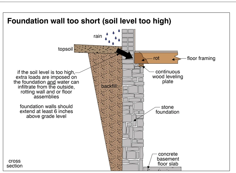
0270Foundation wall too short (soil level too high)
· p. 44
The cross section depicts a stone foundation supporting wood floor framing on a continuous wood leveling plate, with a concrete basement floor slab at its base. Exterior topsoil and backfill rise above the top of the foundation to the masonry wall beside the floor framing. Rain and a heavy inward-pointing arrow illustrate water infiltration from the high exterior grade, with rot indicated at the end of the floor framing. An annotation warns that high soil levels also impose extra loads on the foundation. The illustration states that foundation walls should extend at least 6 inches above grade.
 0271
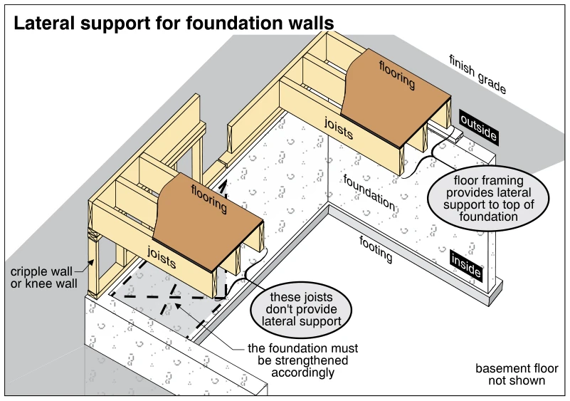
0271Lateral support for foundation walls
· p. 44
The cutaway illustration compares two floor-framing arrangements at foundation walls. On the right, floor joists bear at the top of the foundation, and the framing is identified as providing lateral support to the foundation wall. On the left, a wood-framed cripple wall or knee wall raises the floor framing above the foundation; these joists are identified as not providing lateral support to the foundation. An annotation states that the foundation must be strengthened accordingly. The drawing also identifies the footing, finish grade, and inside and outside faces, with the basement floor omitted.
 0272
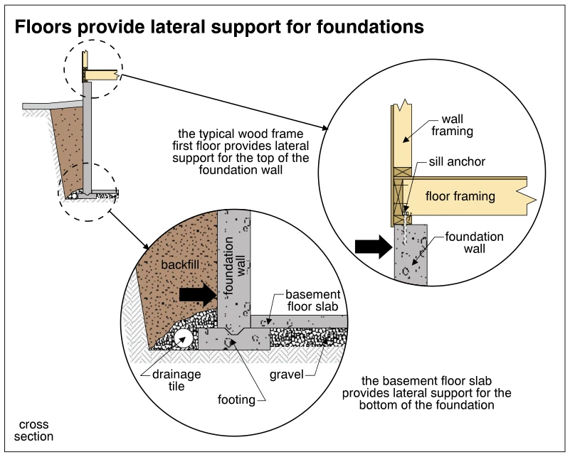
0272Floors provide lateral support for foundations
· p. 44
The illustration shows a cross section of a foundation wall with enlarged details of its top and bottom lateral supports. At the top, wood first-floor framing connects to the foundation through an anchored sill, with wall framing above. At the bottom, the basement floor slab abuts the foundation wall above its footing and provides lateral restraint. Exterior backfill bears against the wall, while gravel and drainage tile are shown beside the footing. Bold arrows indicate inward lateral loading on the foundation wall.
 0273
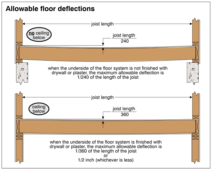
0273Allowable floor deflections
· p. 44
Two sectional diagrams show wood floor joists spanning between end supports, with downward deflection greatest near midspan. Horizontal arrows identify the joist length, and vertical arrows mark the midspan deflection relative to a straight reference line. The upper diagram, labeled no ceiling below, gives a maximum allowable deflection of joist length divided by 240 when the underside is not finished with drywall or plaster. The lower diagram, labeled ceiling below, gives a maximum allowable deflection of joist length divided by 360 or 1/2 inch, whichever is less, when the underside is finished with drywall or plaster.
 0274
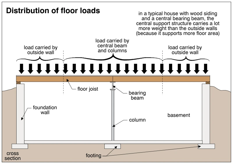
0274Distribution of floor loads
· p. 44
A basement cross section shows floor joists supported by exterior foundation walls and a central bearing beam on a column. Downward arrows represent floor loading, and brackets divide the load between the outside walls and central support structure. The central beam and columns carry load from a larger portion of the floor than either outside wall. The foundation walls and central column transfer their loads to footings below. The illustration explains load distribution without depicting a defect.
Floors ·Sillsp. 45
 0275
0275Air gaps around ends of wooden beams
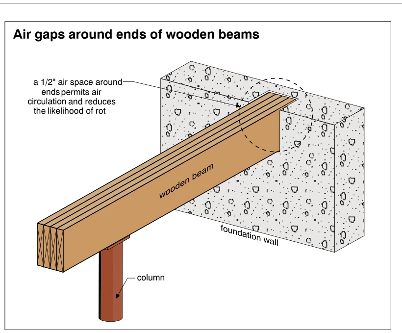
· p. 45
A built-up wooden beam extends into a pocket in a concrete foundation wall and is also supported by a column. The beam end is shown with clearance around it where it enters the wall. An annotation specifies a 1/2-inch air space around the ends to permit air circulation and reduce the likelihood of rot. A dashed circle highlights the beam-to-wall connection.
 0276
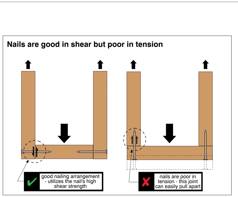
0276Nails are good in shear but poor in tension
· p. 45
The illustration compares two nailed wood assemblies, each with a horizontal member connecting two upright members. Upward arrows above the uprights and downward arrows over the horizontal members indicate opposing loads. In the left arrangement, nails driven horizontally through the uprights into the horizontal member resist the load in shear, and a green check marks this as a good nailing arrangement. In the right arrangement, nails driven upward through the horizontal member into the ends of the uprights are loaded in withdrawal, described as tension in the illustration. A red cross and a dashed displaced outline show that this joint can easily pull apart.
 0277
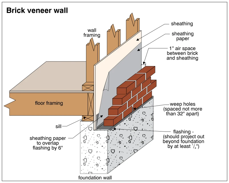
0277Brick veneer wall
· p. 45
The cutaway shows a brick veneer wall outside a wood-framed wall, with floor framing supported on a sill over a concrete foundation wall. Sheathing and sheathing paper cover the wall framing, and a labeled 1-inch air space separates the veneer from the sheathing. Base flashing runs beneath the brick veneer and turns up behind the sheathing paper, which is specified to overlap it by 6 inches. Weep holes at the base of the veneer are specified at no more than 32 inches apart, and the flashing should project at least ¼ inch beyond the foundation. The detail illustrates drainage provisions at the wall-to-foundation junction.
 0278
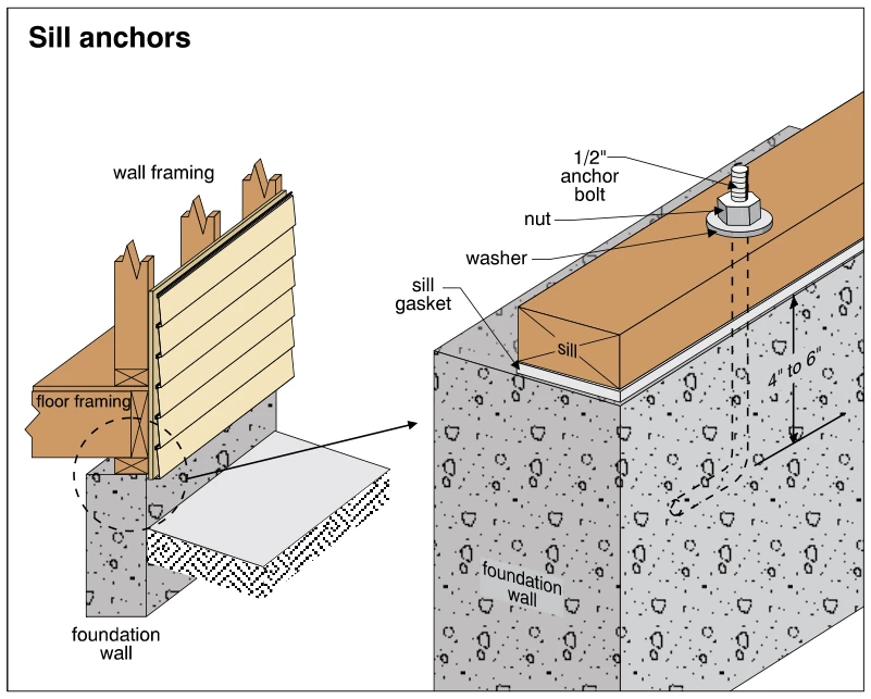
0278Sill anchors
· p. 45
The illustration shows wood wall and floor framing supported on a concrete foundation wall, with an enlarged detail of the sill anchorage. A wood sill rests on a sill gasket separating it from the foundation. A 1/2-inch anchor bolt passes through the sill and is secured above with a washer and nut. Dashed lines show the bent lower end embedded in the concrete, with a 4- to 6-inch embedment dimension indicated.
 0279
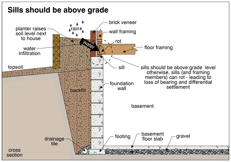
0279Sills should be above grade
· p. 45
The cross section shows a basement foundation wall supporting a wood sill, wall framing, and floor framing, with brick veneer on the exterior. A planter raises the exterior soil level above the sill, and rainwater infiltrating the soil is directed toward the wood framing. Rot is indicated at the sill and floor-framing bearing area. The annotation warns that sills below grade can rot, causing loss of bearing and differential settlement. The lower portion shows foundation backfill, drainage tile beside the footing, and a basement floor slab over gravel.
 0280
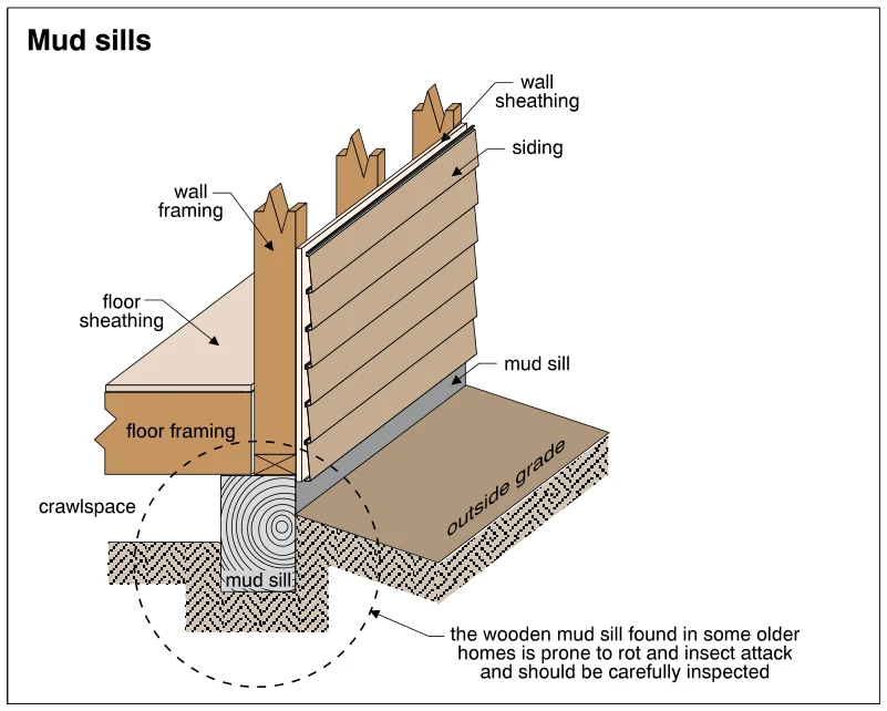
0280Mud sills
· p. 45
The cutaway illustrates an exterior wall and floor assembly supported by a wooden mud sill at the perimeter of a crawlspace. Wall framing, wall sheathing, and horizontal siding are shown above the sill, with floor framing and floor sheathing extending inward. The sill is depicted as a large timber seated directly in the soil below outside grade. A dashed inspection circle highlights this ground-contact condition, and an annotation warns that wooden mud sills in some older homes are prone to rot and insect attack and require careful inspection.
Floors ·Columnsp. 46
 0281
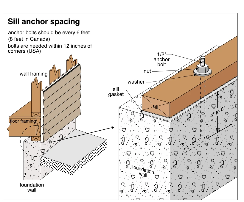
0281Sill anchor spacing
· p. 46
The illustration shows wood wall and floor framing supported on a sill at the top of a concrete foundation wall, with an enlarged detail of the sill anchorage. A 1/2-inch anchor bolt embedded in the foundation passes through the wood sill and is secured with a washer and nut. A sill gasket separates the sill from the concrete, and the embedded bolt has a hooked lower end with a vertical dimension marked 4 to 6 inches. The annotations specify anchor bolts every 6 feet, or 8 feet in Canada, and bolts within 12 inches of corners in the USA.
 0282
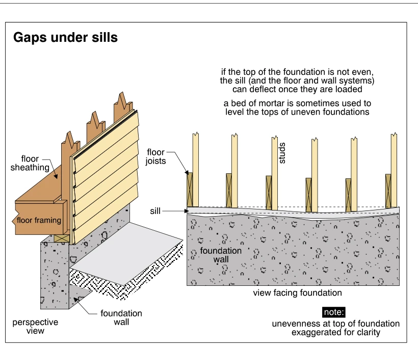
0282Gaps under sills
· p. 46
A perspective cutaway shows wood floor and exterior wall framing supported on a sill over a concrete foundation wall. An adjacent elevation shows an uneven foundation top beneath the sill, with floor joists and wall studs above. The uneven support allows the sill and the supported floor and wall systems to deflect under load. A dashed reference line emphasizes the variation in elevation, which is exaggerated for clarity. The annotation identifies a mortar bed as a possible means of leveling uneven foundation tops.
 0283
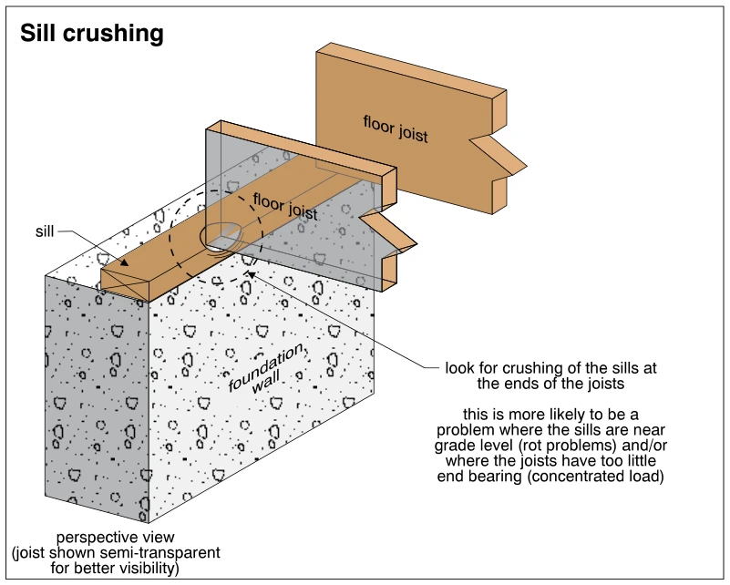
0283Sill crushing
· p. 46
The perspective drawing shows wood floor joists bearing on a wood sill atop a concrete foundation wall. One joist is shown semi-transparent to expose its bearing contact with the sill. A circled area and leader identify sill crushing beneath the joist end as an inspection concern. The annotation explains that crushing is more likely where sills are near grade and susceptible to rot, or where insufficient joist end bearing concentrates the load.
 0284
0284Column types
· p. 46
The illustration shows wood, steel, and concrete structural column types. The wood examples include a fastened built-up column supporting a beam, a square solid column, and a round column. Wrapped barriers at the wood column bases are identified as polyethylene or type S roll roofing to prevent direct wood-to-concrete contact. The steel column supports a beam through a top bearing plate and has a base plate. Concrete examples include square and round solid columns and a column built from stacked hollow concrete masonry units.
 0285
0285Reasons for column settling
· p. 46
Four side-by-side sectional diagrams show reasons a structural support column may settle. Each column supports a bearing beam beneath a loaded floor joist, with its base at a concrete floor slab over gravel and soil. The first example shows an undersized footing, and the second shows a column supported without a footing. The third depicts poor soil conditions beneath the footing, while the fourth uses larger downward arrows to indicate a greater-than-intended load on the column. Downward arrows below each assembly emphasize the resulting settlement.
 0286
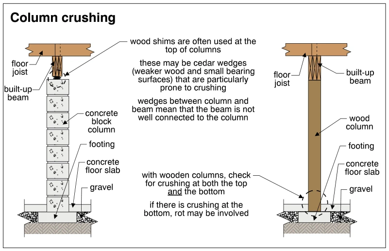
0286Column crushing
· p. 46
Two section diagrams show a concrete block column and a wood column supporting built-up beams beneath floor joists. Both columns bear on footings at the concrete floor slab, with gravel shown beneath the slab. The concrete block column has wood shims between its top and the beam; annotations warn that cedar wedges with small bearing surfaces are prone to crushing and leave the beam poorly connected to the column. The wood-column diagram identifies the top and bottom as locations to check for crushing, with the base highlighted by a dashed outline. An annotation notes that crushing at the bottom may involve rot.
 0287
0287The 1/3 rule for wall stability
· p. 47
The illustration compares an upright wall, two progressively leaning walls, and a bowed wall using the middle-third rule for stability. Each wall has its middle third shaded, a center-of-gravity marker, and a vertical downward arrow showing the gravity force line relative to its base. The upright wall is labeled stable, the slightly leaning wall borderline, and the more tilted and bowed walls unstable because the gravity line falls outside the middle third at the base. Horizontal arrows indicate lateral forces on the walls. The printed procedure calls for measuring the out-of-plumb displacement and making a scale diagram, and notes that walls supporting joists tolerate even less lean.
 0288
0288Column sizes
· p. 47
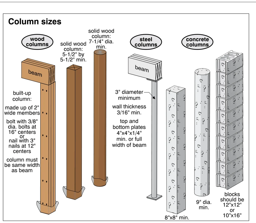
The illustration presents column sizes for built-up wood, solid wood, steel, concrete, and concrete block supports. The built-up wood column supports a beam and is annotated with member width, fastening requirements, and a requirement that the column match the beam width. Square and round solid wood columns are labeled with minimum dimensions of 5-1/2 inches square and 7-1/4 inches diameter, respectively. A tubular steel column supporting a beam is shown with top and bottom bearing plates and notes specifying minimum diameter, wall thickness, and plate dimensions. Square and round concrete columns and a stacked concrete block column are shown with their respective size annotations.
 0288.5
Adjustable steel columns
· p. 47
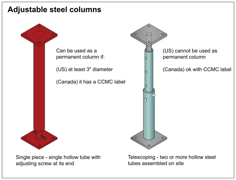
The illustration compares single-piece and telescoping adjustable steel columns, both with square top and base plates. The single-piece column has one hollow tube and an adjusting screw at its lower end. The telescoping column has nested hollow tubes, adjustment holes, a locking pin, and an upper screw adjustment. The annotations state that the single-piece column can serve as a permanent column in the US if it is at least 3 inches in diameter, and in Canada if it has a CCMC label. The telescoping column is identified as unsuitable for permanent use in the US but acceptable in Canada with a CCMC label.
 0289
0289Column buckling
· p. 47
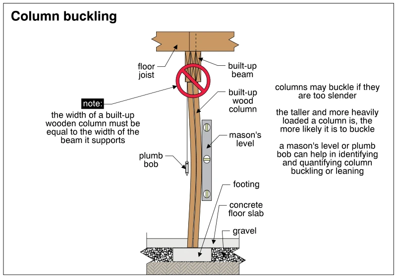
The illustration shows a bowed built-up wood column supporting a built-up beam beneath a floor joist. The column rests on a footing below a concrete floor slab with gravel beneath it. A prohibition symbol highlights the column-to-beam connection, accompanied by a note that the built-up column must equal the width of the beam it supports. A mason's level and plumb bob are shown beside the column to illustrate checking for buckling or leaning. Annotations explain that slenderness, height, and heavier loading increase the likelihood of column buckling.
 0290
0290Column connections
· p. 47
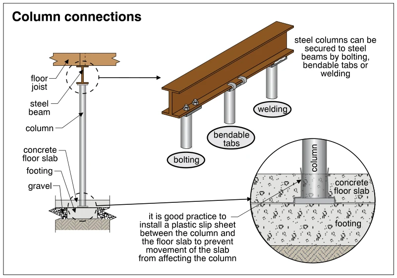
The illustration shows a steel column supporting a steel beam beneath a floor joist, with the column base bearing on a footing below a concrete floor slab. An enlarged beam detail illustrates three ways to secure steel columns to steel beams: bolting, bendable tabs, and welding. The foundation section shows gravel adjacent to the footing beneath the slab. An enlarged column-base detail shows a plastic slip sheet separating the column from the floor slab so slab movement does not affect the column.
 0291
0291Rising damp in masonry columns
· p. 47
The illustration shows a brick masonry column supporting a bearing beam beneath a floor joist. The column extends through a concrete floor slab into wet soil below, with the water level marked near the slab. Large upward arrows show water rising into the column bricks by capillary action. Annotations explain that this moisture can weaken the brick or mortar and advise checking for efflorescence and deterioration around the column base.
Floors ·Beamsp. 48
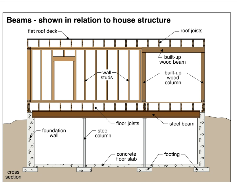 0292
0292Beams - shown in relation to house structure
· p. 48
This cross section shows beams in relation to a house's wood framing and foundation structure. Roof joists beneath a flat roof deck bear on stud walls and a built-up wood beam spanning an opening supported by built-up wood columns. Floor joists are shown above a steel beam, which is supported by steel columns and the foundation walls. The basement includes a concrete floor slab, with footings beneath the steel columns and foundation walls. The illustration identifies structural components without depicting a defect.
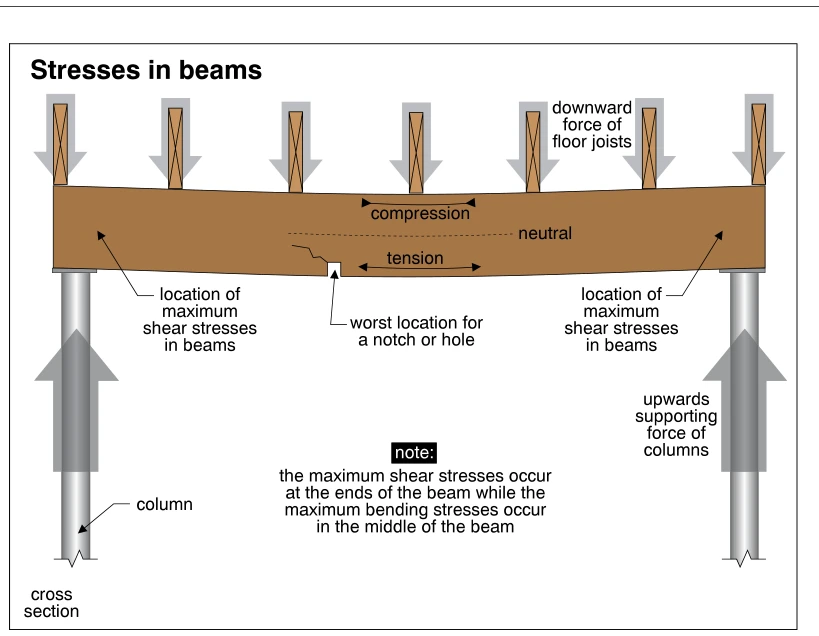 0293
0293Stresses in beams
· p. 48
The cross-section diagram shows a beam supported by columns at both ends and loaded downward by floor joists along its length. The beam is drawn bending downward, with compression at the top, tension at the bottom, and a dashed neutral line between them. Arrows identify maximum shear stresses near the end supports, while a note identifies maximum bending stresses in the middle of the span. A notch in the bottom edge toward midspan is labeled as the worst location for a notch or hole, and an irregular line extends from the notch into the beam. Large upward arrows illustrate the supporting forces supplied by the columns.
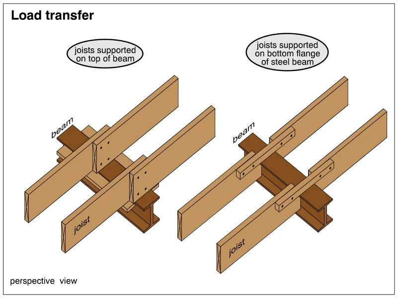 0294
0294Load transfer
· p. 48
Two perspective details illustrate wood floor joists transferring loads to steel I-beams. In the left detail, opposing joists overlap above the beam and bear on its top flange. In the right detail, joist ends sit lower, supported on the beam's bottom flange, with wood connecting pieces fastened along their sides across the beam location. The illustration compares two bearing arrangements without identifying either as defective.
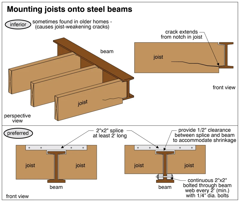 0295
0295Mounting joists onto steel beams
· p. 48
The illustration compares inferior and preferred methods of mounting wood joists onto steel I-beams. The upper perspective and front views show joist ends notched to fit between the beam flanges, with a crack extending into a joist from its lower notch. The lower front views show preferred arrangements with a 2-by-2 splice at least 2 feet long joining opposing joists above the beam. One arrangement includes continuous 2-by-2 supports bolted through the beam web and specifies a half-inch clearance between the splice and beam to accommodate wood shrinkage.
 0296
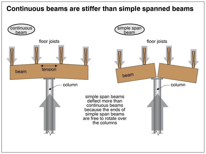
0296Continuous beams are stiffer than simple spanned beams
· p. 48
The illustration compares a continuous beam passing over a column with two simple-span beams meeting above a column. Floor joists impose downward loads on both assemblies, while upward arrows indicate support reactions at the columns. The continuous beam is shown bending across the support, with tension indicated along its upper surface over the column. The simple-span beam ends rotate independently at the support, illustrating greater deflection than the continuous arrangement.
 0297
0297Sight along beams to check for sag
· p. 48
The illustration shows side and perspective views of a wood beam spanning between brick masonry piers. A mason's level is placed against the underside of the beam in the side view, where slight sag is difficult to recognize. The perspective view exposes the beam's curved bottom edge along its span. The annotations recommend sighting along the bottom edge to obtain a clearer indication of beam sag.
 0298
0298Support for beam ends
· p. 49
A perspective view shows a basement steel beam supported at its end by a foundation-wall pilaster and farther along by a column on a footing. The basement floor is omitted for clarity, and the surrounding finish grade is indicated outside the foundation walls. An enlarged detail shows the beam end resting on stacked steel plate shims at the foundation wall, with a minimum bearing length of 3 inches, or 3½ inches in Canada. Annotations recommend welding the steel plate shims together and to the beam, and warn against supporting steel beams or columns on wood or pieces of brick.
 0299
0299Air gaps around ends of wooden beams
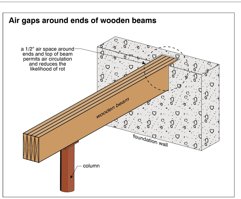
· p. 49
A built-up wooden beam extends into a pocket in a concrete foundation wall and is also supported by a column. A dashed circle highlights the beam end at the wall pocket. The annotation specifies a 1/2-inch air space around the ends and top of the beam to permit air circulation and reduce the likelihood of rot. The illustration presents this clearance as proper detailing for a wood beam bearing in a foundation wall.
 0300
0300Rotated or twisted beams
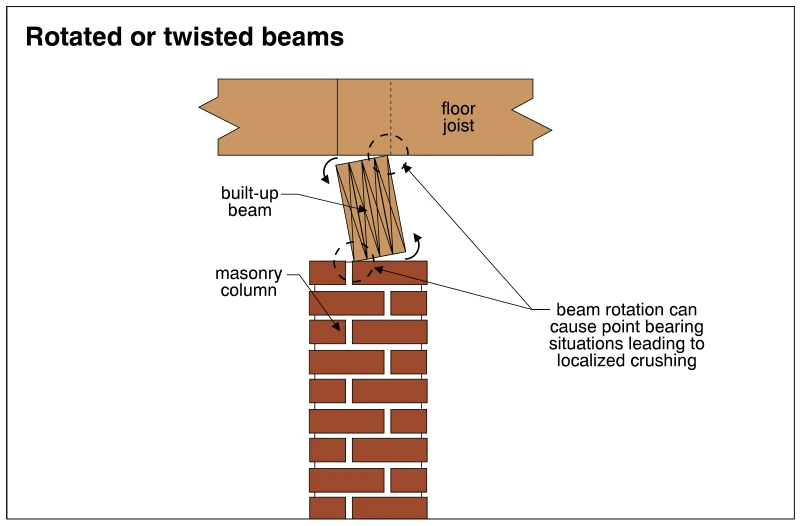
· p. 49
The illustration shows a built-up wood beam supporting a floor joist and bearing on a masonry column. The beam is rotated out of its upright position, with curved arrows indicating rotation. Its tilted cross-section creates concentrated contact at the joist above and the column below rather than full-width bearing. Dashed circles highlight these contact areas, and the annotation warns that point bearing can lead to localized crushing.
 0301
0301Notches or holes not allowed in beams
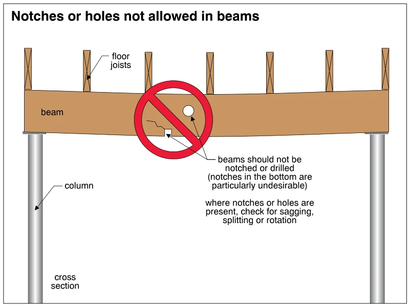
· p. 49
A cross-sectional illustration shows a wood beam supporting floor joists and bearing on columns at both ends. Near midspan, the beam has a circular drilled hole, a notch in its bottom edge, and a jagged split adjacent to the notch. A red prohibition symbol emphasizes that beams should not be notched or drilled, particularly along the bottom edge. The annotation directs inspectors to check for sagging, splitting, or rotation wherever holes or notches are present.
 0302
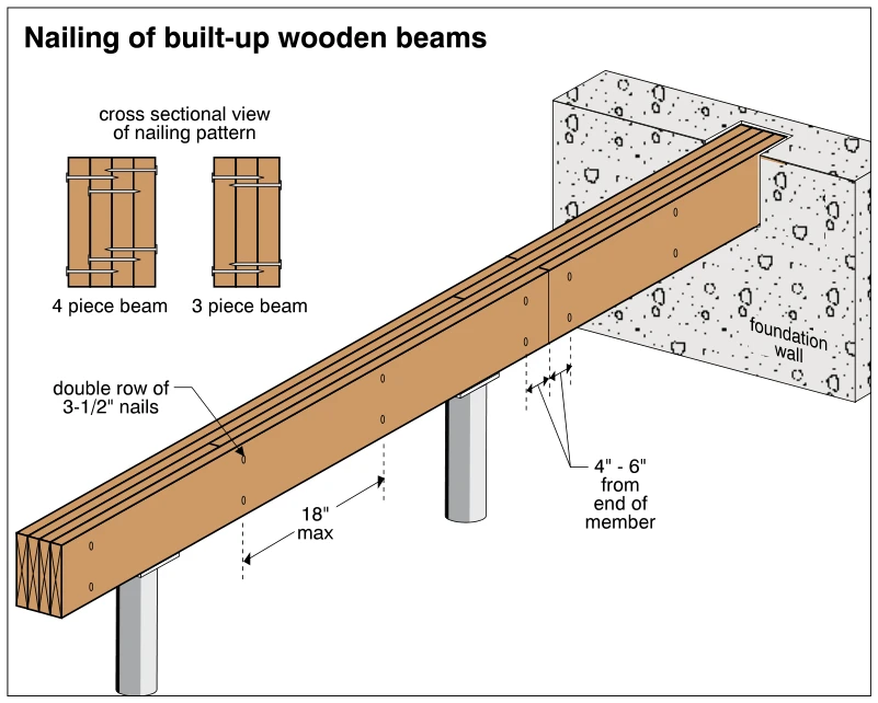
0302Nailing of built-up wooden beams
· p. 49
The illustration shows a built-up wooden beam supported by columns and seated in a pocket in a foundation wall. The beam consists of side-by-side lumber plies fastened with a double row of 3-1/2-inch nails. Dimension annotations specify a maximum 18-inch spacing along the beam and nail placement 4 to 6 inches from the end of a member. Cross-sectional insets illustrate nailing patterns from opposite faces for three-piece and four-piece beams.
 0303
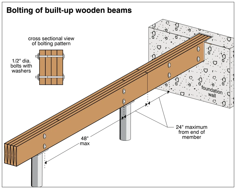
0303Bolting of built-up wooden beams
· p. 49
The illustration shows a built-up wooden beam composed of parallel lumber plies, supported by posts and seated in a pocket in a foundation wall. Pairs of through-bolts are positioned vertically along the beam to connect the plies. A cross-sectional inset shows 1/2-inch-diameter bolts with washers passing through the full beam width. Dimension annotations specify a maximum spacing of 48 inches between bolt locations and a maximum distance of 24 inches from the end of a member.
 0304
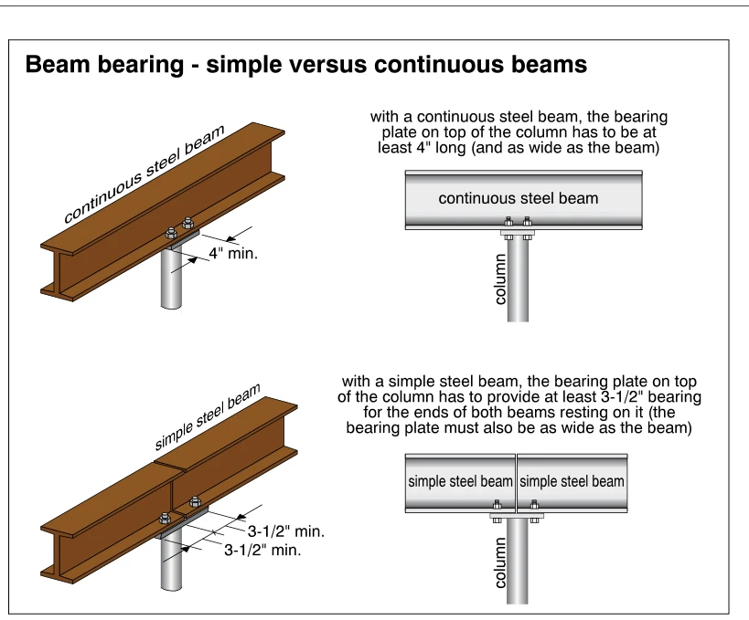
0304Beam bearing - simple versus continuous beams
· p. 50
The illustration compares column bearing requirements for continuous steel beams and simple steel beams using perspective and elevation views. The upper diagrams show a continuous I-beam passing over a column, with a bearing plate at least 4 inches long and as wide as the beam. The lower diagrams show two simple I-beams meeting end-to-end over a column, with the bearing plate providing at least 3-1/2 inches of bearing for each beam end and matching the beam width. Bolted connections are shown at the beam bottom flanges and column bearing plates.
 0305
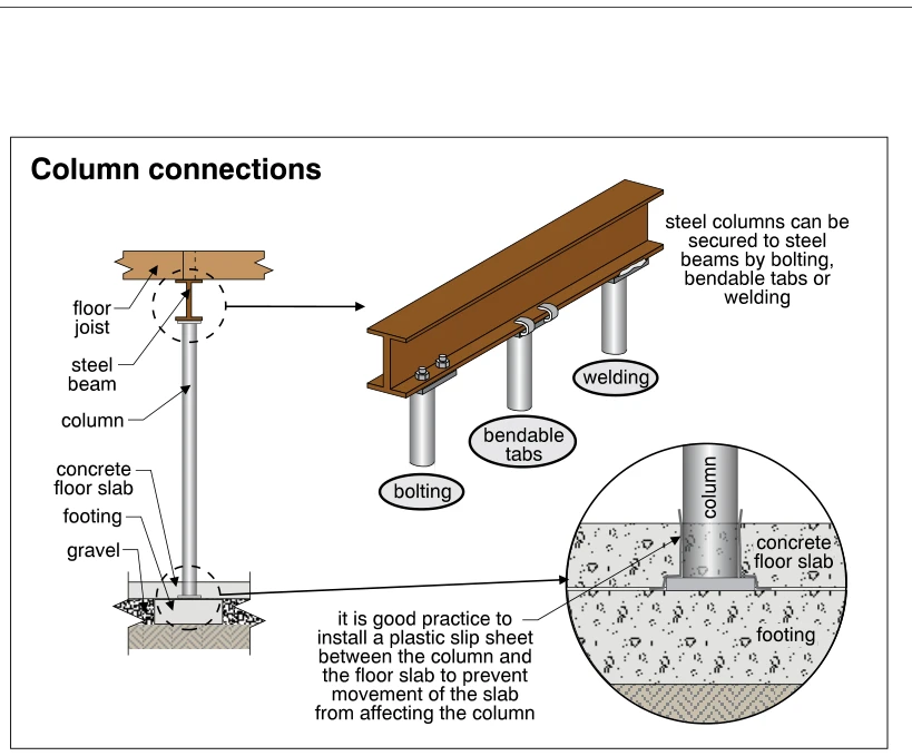
0305Column connections
· p. 50
The illustration shows a steel column supporting a steel beam beneath a floor joist, with the column base bearing on a footing below a concrete floor slab. An enlarged beam detail shows three methods of securing steel columns to the beam: bolting, bendable tabs, and welding. A circular base detail shows the column passing through the slab to its base plate on the footing. A plastic slip sheet separates the column from the slab to prevent slab movement from affecting the column.
 0306
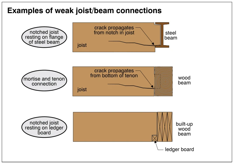
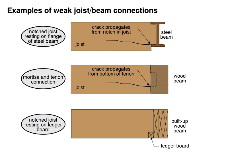
0306Examples of weak joist/beam connections
· p. 50
The illustration shows three examples of weak wood joist-to-beam connections. The upper detail shows a notched joist bearing on the bottom flange of a steel beam, with a crack propagating inward from the notch. The middle detail shows a mortise-and-tenon connection to a wood beam, with a crack extending into the joist from the bottom of the tenon. The lower detail shows a bottom-notched joist resting on a ledger board attached to the side of a built-up wood beam.
 0307
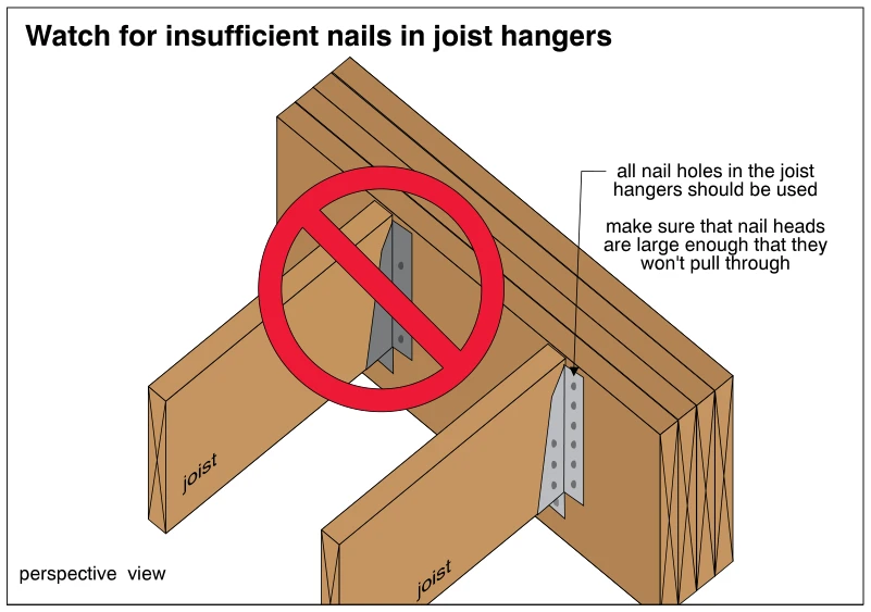
0307Watch for insufficient nails in joist hangers
· p. 50
The perspective drawing shows two wood joists connected to a built-up wood beam with metal joist hangers. A red prohibition symbol overlays the left connection, highlighting insufficient nailing of the hanger. The right hanger exposes rows of fastening locations on its flanges. Annotations state that all nail holes in the hangers should be used and that nail heads must be large enough to prevent pull-through.
 0308
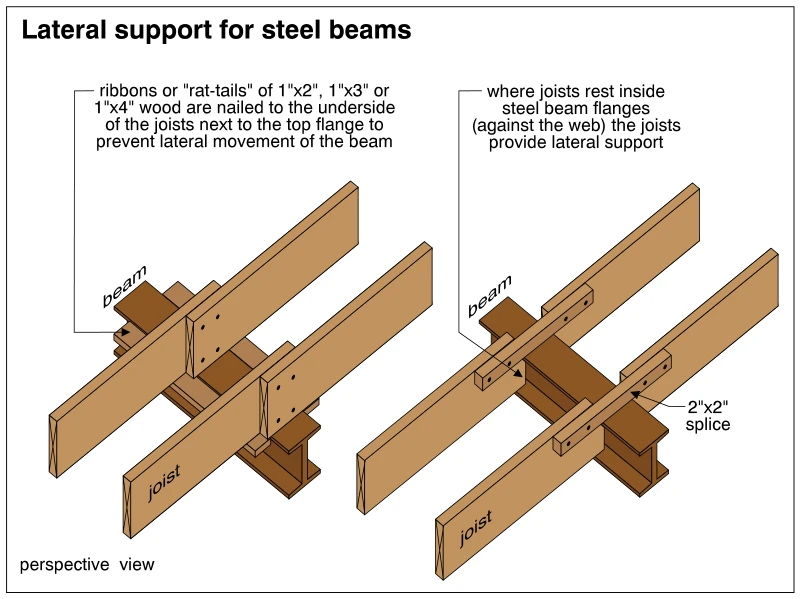
0308Lateral support for steel beams
· p. 50
Two perspective details illustrate ways wood floor joists provide lateral support for a steel I-beam. In the left detail, joists bear on the top flange, with wood ribbons or "rat-tails" nailed to their undersides alongside the flange to restrain lateral beam movement. In the right detail, joist ends fit between the beam flanges and rest against the web, providing lateral support directly. The right detail also shows nailed 2-by-2 wood splices along the sides of the joists across the beam.
 0309
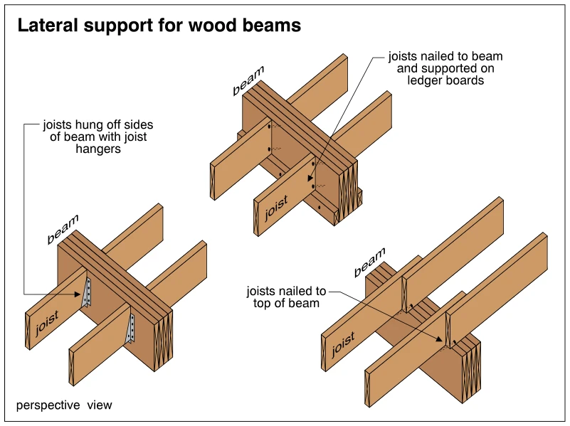
0309Lateral support for wood beams
· p. 50
Three perspective details illustrate ways floor joists provide lateral support for built-up wood beams. One detail shows joists attached to the sides of a beam with metal joist hangers. Another shows joists nailed to the beam sides and bearing on ledger boards along the lower edges of the beam. The third shows joists bearing on and nailed to the top of a beam. These connections restrain the beam laterally; no defective installation is depicted.
Floors ·Joistsp. 51
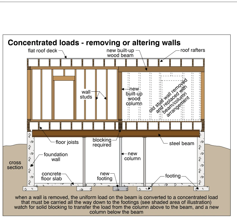 0310
0310Concentrated loads - removing or altering walls
· p. 51
The cross section shows a wood-framed building with a flat roof, floor joists, a basement steel beam, foundation walls, and a concrete floor slab. Dashed lines indicate a removed stud wall, replaced by a new built-up wood beam and wood column. The highlighted load path passes from the new wood column through required solid blocking in the floor framing to the steel beam below. A new column beneath the steel beam carries this concentrated load to a new footing. The illustration emphasizes that replacing a uniformly supporting wall with a beam-and-column arrangement requires continuous support down to the footings.
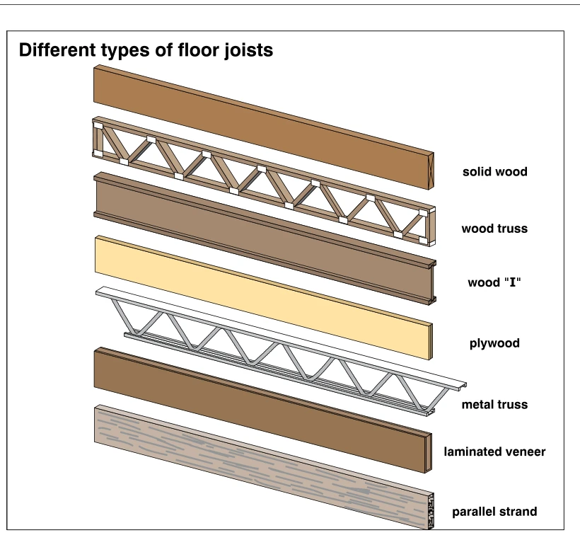 0311
0311Different types of floor joists
· p. 51
The illustration shows seven types of floor joists as separate members arranged vertically for identification. Solid wood, plywood, laminated veneer, and parallel strand members have continuous rectangular profiles. The wood truss has upper and lower chords connected by diagonal web members, with connector plates shown at the joints. The wood I-joist has a continuous web between projecting top and bottom flanges, while the metal truss has an open triangular web between its chords. No installed floor assembly, defects, or improper practices are depicted.
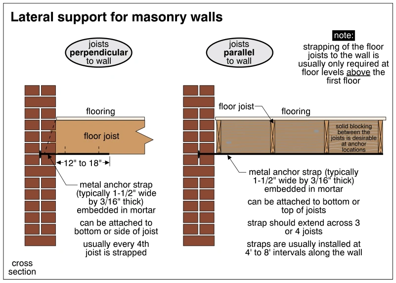 0312
0312Lateral support for masonry walls
· p. 51
Two cross-sectional details show floor framing providing lateral support to masonry walls through metal anchor straps embedded in mortar joints. With joists perpendicular to the wall, the strap attaches to the bottom or side of a joist, with a labeled 12- to 18-inch dimension and a note that usually every fourth joist is strapped. With joists parallel to the wall, the strap attaches to the bottom or top of the joists and should extend across three or four joists. Solid blocking is identified as desirable at anchor locations, and straps along the wall are noted as usually spaced at 4- to 8-foot intervals. A general note states that this strapping is usually only required at floor levels above the first floor.
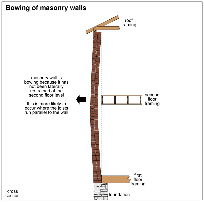 0313
0313Bowing of masonry walls
· p. 51
The cross section shows a masonry wall extending from a foundation to wood roof framing, with first- and second-floor framing on its interior side. The wall bows outward near the second-floor level, illustrated by a left-pointing arrow and a dashed vertical reference line. The second-floor framing is shown separated from the wall without lateral restraint. The annotation identifies the missing lateral restraint as the cause of bowing and notes that this is more likely where joists run parallel to the wall.
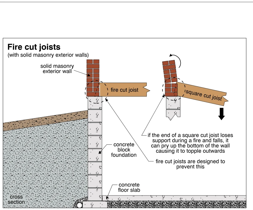 0314
0314Fire cut joists
· p. 52
The illustration compares fire-cut and square-cut wood joists bearing in a solid masonry exterior wall above a concrete block foundation. The main cross section shows a fire-cut joist with its embedded end beveled to provide clearance as the joist falls. An inset shows a square-cut joist rotating downward and prying against the masonry, causing the wall above to tilt outward. The annotations explain that fire-cut joists are designed to prevent this wall-toppling action when joists lose support during a fire. A concrete floor slab and below-grade foundation are also shown.
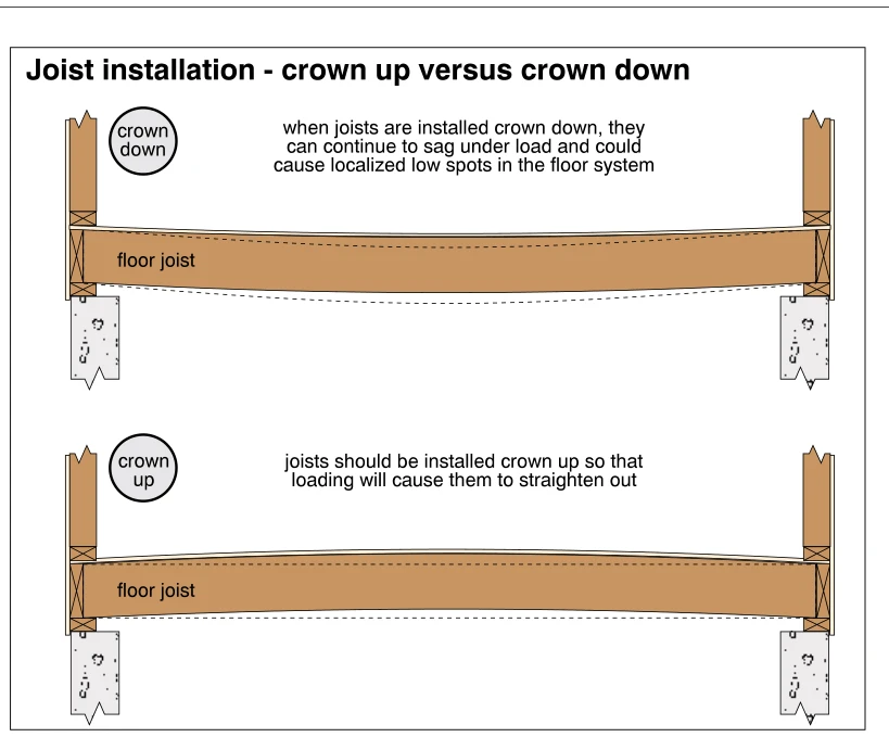 0315
0315Joist installation - crown up versus crown down
· p. 52
The illustration compares two orientations of a wood floor joist spanning between supported wall assemblies. The upper drawing shows a joist installed crown down, with a downward bow that can increase under loading and produce localized low spots in the floor. The lower drawing shows the recommended crown-up orientation, with an upward bow that straightens under loading. Dashed outlines indicate the change in joist shape under load, and both assemblies show joist ends supported above concrete foundation walls.
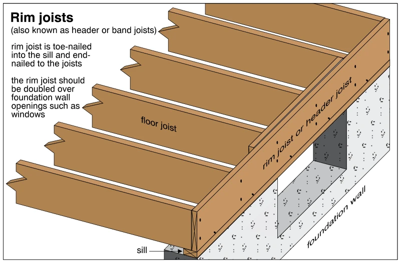 0316
0316Rim joists
· p. 52
The illustration shows wood floor joists terminating at a rim joist along the perimeter of a concrete foundation wall. The rim joist runs perpendicular to the floor joists and rests on a sill at the top of the foundation. Nail marks and an annotation indicate that the rim joist is toe-nailed into the sill and end-nailed to the floor joists. A rectangular opening is shown in the foundation wall, with additional rim framing above it illustrating the instruction to double the rim joist over openings such as windows.
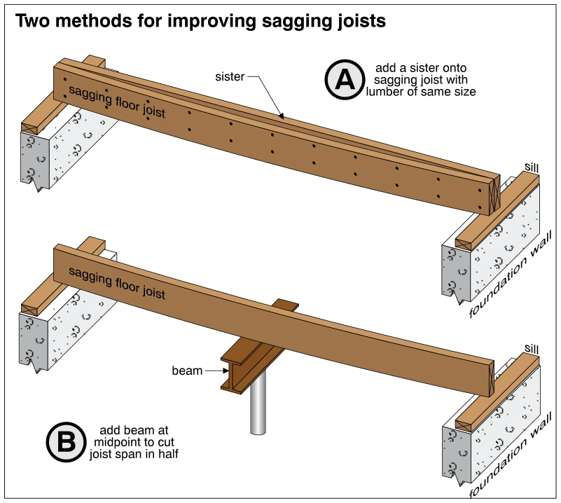 0317
0317Two methods for improving sagging joists
· p. 52
The illustration shows two methods for improving a sagging wood floor joist spanning between sills on foundation walls. Method A adds a same-size lumber sister alongside the existing joist, with fasteners shown along its length. Method B adds an intermediate beam beneath the joist at its midpoint to cut the unsupported span in half. The intermediate support is depicted as an I-section beam supported by a round column.
 0318
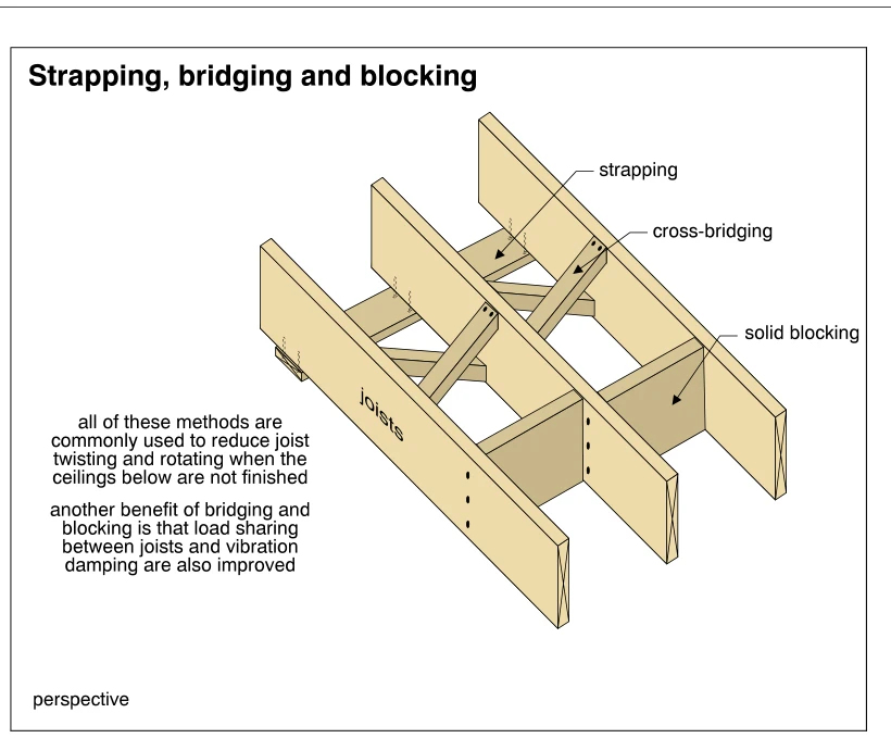
0318Strapping, bridging and blocking
· p. 53
A perspective drawing shows three parallel wood floor joists with examples of strapping, cross-bridging, and solid blocking. Strapping runs across the undersides of the joists, while diagonal cross-bridging forms X-shaped braces between adjacent joists. Solid wood blocks fit vertically between the joists, with fasteners indicated through the joist faces. The annotations explain that these methods reduce joist twisting and rotation where ceilings below are unfinished, and that bridging and blocking also improve load sharing and vibration damping.
 0319
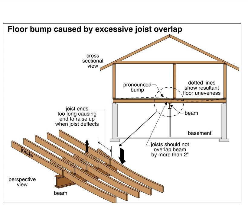
0319Floor bump caused by excessive joist overlap
· p. 53
The illustration combines a house cross section with a perspective detail of floor joists overlapping above a basement support beam. The joist ends extend excessively beyond the beam, and arrows show how downward joist deflection lifts the projecting ends. In the cross section, dotted lines indicate resultant floor unevenness, including a pronounced bump over the beam. An annotation states that joists should not overlap the beam by more than 2 inches.
 0320
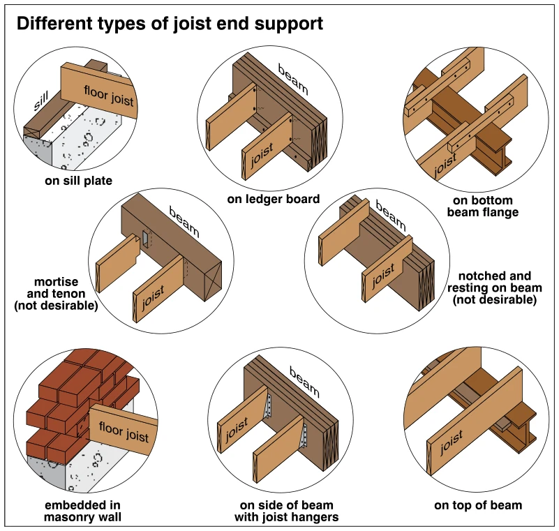
0320Different types of joist end support
· p. 53
Eight detail views compare different ways to support wood floor joist ends. The examples show bearing on a sill plate, support on a ledger board attached to a wood beam, and bearing on the bottom flange of a steel beam. Mortise-and-tenon connections and joists notched to rest on a beam are explicitly identified as not desirable. Additional views show joist ends embedded in a masonry wall, attached to the side of a wood beam with metal joist hangers, and resting on top of a steel beam.
 0321
0321Examples of weak joist/beam connections
· p. 53
The illustration shows three examples of weak connections between wood joists and supporting beams. At the top, a notched joist rests on the lower flange of a steel beam, with a crack extending into the joist from the notch. The middle example shows a mortise and tenon connection to a wood beam, with a crack propagating into the joist from the bottom of the tenon. The bottom example shows a notched joist supported on a ledger board alongside a built-up wood beam. All three details are presented as weak joist/beam connections.
 0322
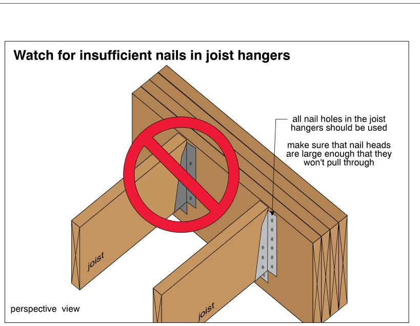
0322Watch for insufficient nails in joist hangers
· p. 54
A perspective drawing shows two wood joists connected to a built-up wood support member with metal joist hangers. A red prohibition symbol overlays the left connection, identifying insufficient nailing as improper. The right hanger illustrates the multiple fastening locations along its flanges. Annotations state that all nail holes should be used and that nail heads must be large enough to prevent pull-through.
 0323
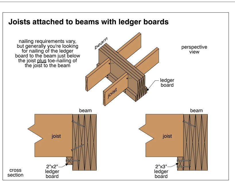
0323Joists attached to beams with ledger boards
· p. 54
The illustration shows wood joists attached to the sides of a built-up wood beam, with ledger boards supporting the joist ends from below. A perspective view shows the relationship between the beam, joists, and ledger boards. Two cross sections illustrate 2"x2" and 2"x3" ledger boards nailed to the beam, with the joists also toe-nailed into the beam. The annotation states that nailing requirements vary but generally calls for fastening the ledger to the beam just below the joist and toe-nailing the joist to the beam.
 0324
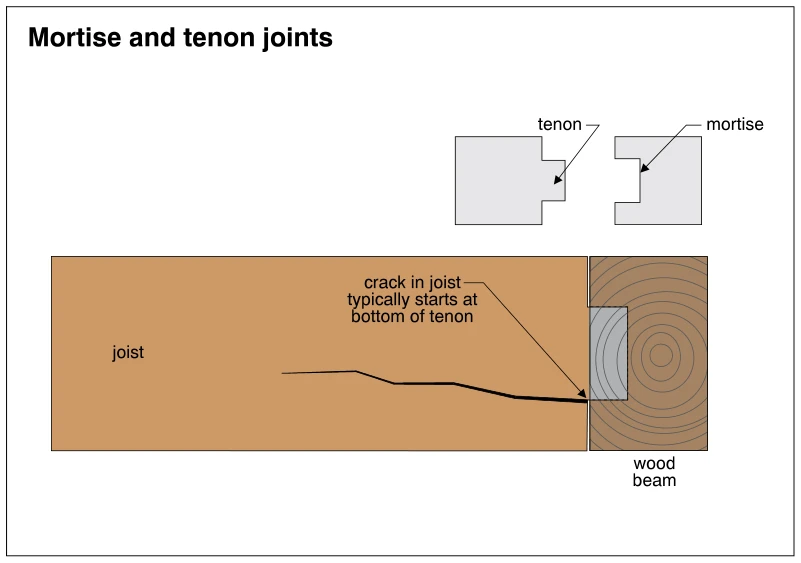
0324Mortise and tenon joints
· p. 54
The illustration shows a wood joist joined to a wood beam with a mortise-and-tenon connection. Small diagrams above the assembly identify the projecting tenon and the matching mortise recess. The main drawing shows the joist tenon seated in the side of the beam, which is drawn in cross section with growth rings. A crack extends back into the joist from the bottom of the tenon, identified as the typical starting point for cracking.
 0325
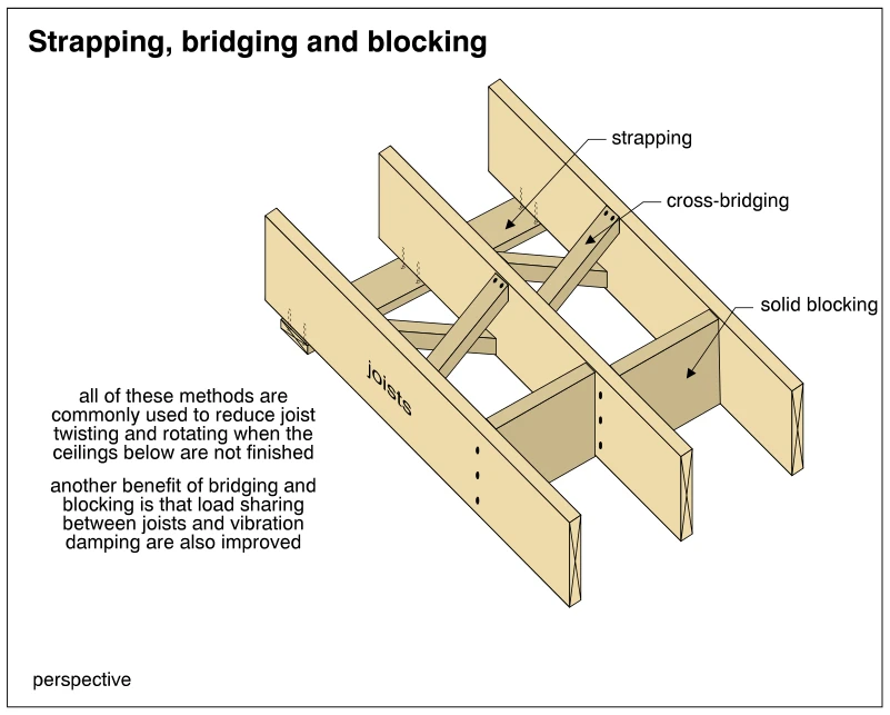
0325Strapping, bridging and blocking
· p. 54
A perspective drawing shows three parallel wood floor joists with strapping, cross-bridging, and solid blocking illustrated as methods of lateral restraint. Strapping runs across the undersides of the joists, while diagonal cross-bridging forms X-shaped braces between adjacent joists. Full-depth solid blocks fit between the joists, with fasteners shown through the joist faces at the block ends. The annotations explain that these methods reduce joist twisting and rotation when ceilings below are unfinished, and that bridging and blocking also improve load sharing and vibration damping.
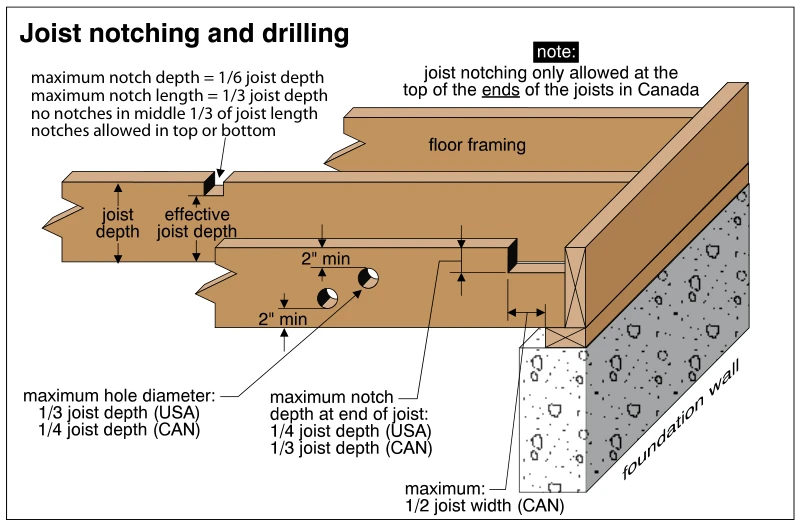 0326
0326Joist notching and drilling
· p. 54
The illustration shows wood floor joists supported at a concrete foundation wall, with examples of drilled holes and top notches. Dimension arrows distinguish full joist depth from the effective depth remaining below a notch. Two drilled holes illustrate minimum 2-inch clearance from joist edges, with maximum hole diameters specified separately for the USA and Canada. An end notch is shown near the joist bearing, with limits on notch depth and length. Notes give general notch restrictions, prohibit notches in the middle third of the span, and identify a Canadian restriction limiting notching to the tops of joist ends.
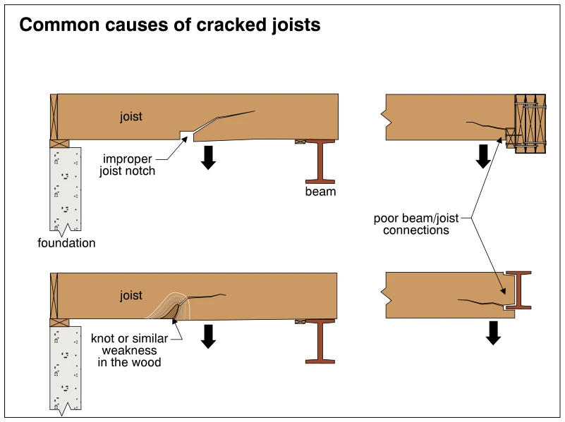 0327
0327Common causes of cracked joists
· p. 54
Four details illustrate causes of cracking in wood floor joists, with downward arrows indicating loading or movement. The upper-left joist spans between a foundation and a beam and has a crack extending from an improper notch in its lower edge. The lower-left detail shows a crack originating at a knot or similar weakness in the wood. The two right-hand details show cracked joist ends at poor connections to a wood member and a steel I-beam.
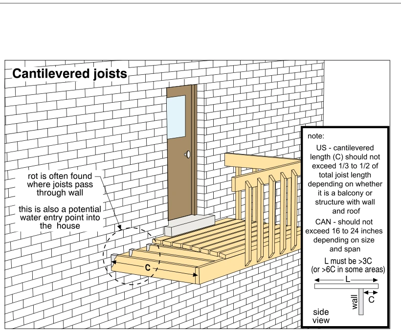 0328
0328Cantilevered joists
· p. 55
The illustration shows a wood balcony supported by cantilevered floor joists projecting through a brick-pattern exterior wall. Deck boards, perimeter framing, and a wood guard are shown beside an exterior door and threshold. A dashed circle highlights the joist penetrations, with annotations identifying potential rot and water entry into the house. Dimension C indicates the cantilever projection, and an inset side view relates it to total joist length L. Notes give US and Canadian limits on cantilever length and length ratios.
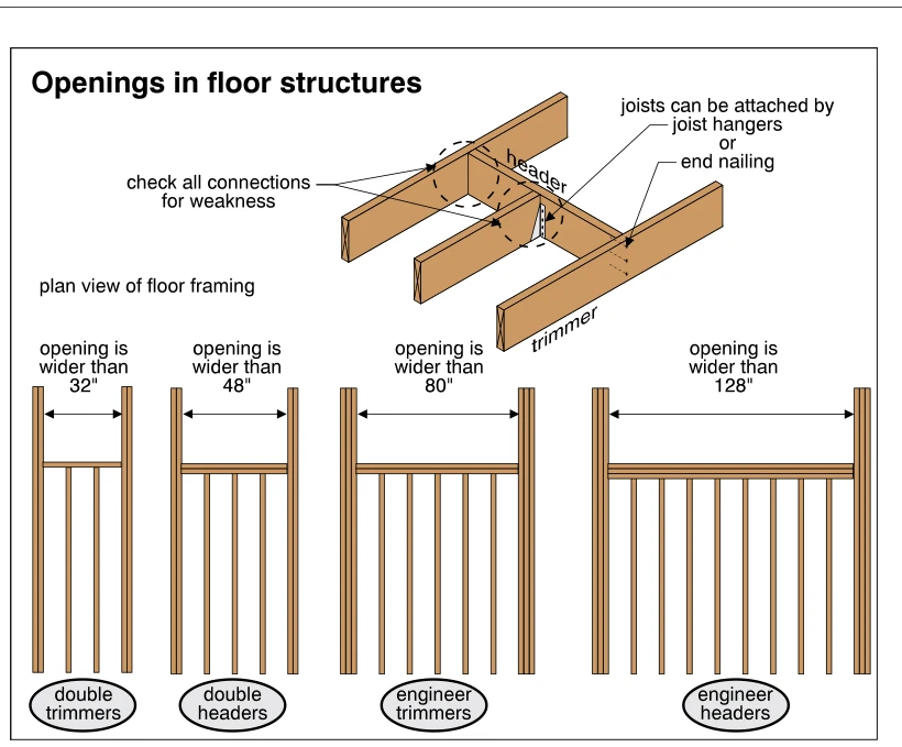 0329
0329Openings in floor structures
· p. 55
The illustration depicts wood floor framing around openings, with interrupted joists terminating at a header supported by trimmer joists. A perspective detail shows joist attachment by joist hangers or end nailing and directs inspectors to check all connections for weakness. Four plan views identify progressively greater reinforcement requirements as opening width increases: double trimmers above 32 inches, double headers above 48 inches, engineered trimmers above 80 inches, and engineered headers above 128 inches. The drawings emphasize the header-to-trimmer connections and the framing members that carry loads around the opening.
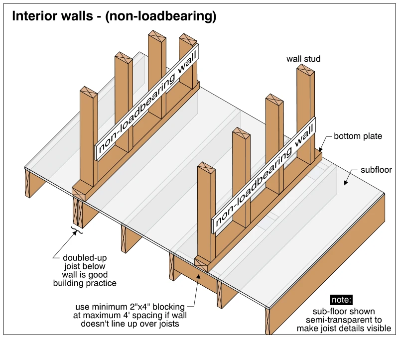 0330
0330Interior walls - (non-loadbearing)
· p. 55
The illustration shows two non-loadbearing interior stud walls installed over a wood-framed floor, with the subfloor drawn semi-transparent to expose the joists. Both walls run parallel to the floor joists. One wall sits over a doubled-up joist, identified as good building practice. The other wall lies between joists, with transverse blocking beneath it. The annotation specifies minimum 2-inch by 4-inch blocking at maximum 4-foot spacing where a wall does not line up over joists.
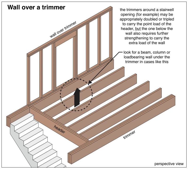 0331
0331Wall over a trimmer
· p. 55
The perspective drawing shows wood floor joists and a header framing a stairwell opening between built-up trimmers. A stud wall with a framed opening sits directly above one trimmer. The annotation explains that doubled or tripled trimmers may carry the header's point load but require further strengthening where they also support a wall. A dashed circle and upward arrow highlight the support location beneath the wall-bearing trimmer, with a callout directing the inspector to look for a beam, column, or loadbearing wall below.
Floors ·Subflooringp. 56
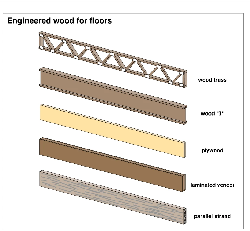 0332
0332Engineered wood for floors
· p. 56
The illustration shows five engineered wood products for floor construction, arranged vertically as separate perspective views. The wood truss has top and bottom chords connected by triangulated web members, with connection plates indicated at the joints. The wood I-section has narrow top and bottom flanges joined by a continuous web. Below these are rectangular members labeled plywood, laminated veneer, and parallel strand, with edge layering or strand patterns distinguishing their construction. This is an informational comparison of product forms; no installation details or defects are depicted.
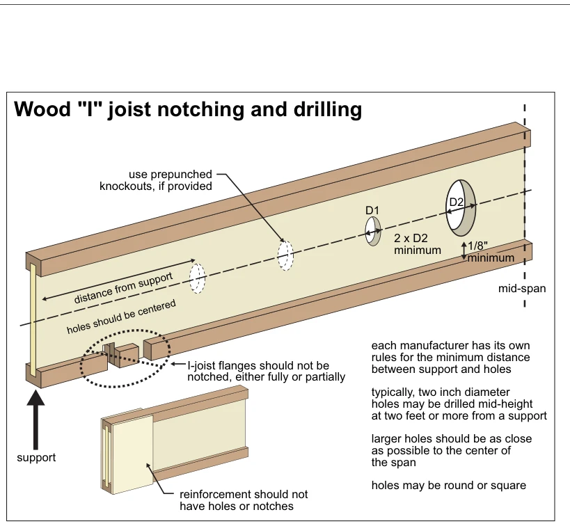 0332.5
Wood "I" joist notching and drilling
· p. 56
The illustration shows a wood I-joist extending from a support toward mid-span, with upper and lower flanges and holes through the web. Holes are located along the web centerline, with dimensions identifying minimum hole spacing and clearance from a flange. Notes direct users to manufacturer-specific support clearances, prepunched knockouts where provided, and placement of larger holes near mid-span. Circled partial and full notches in the lower flange illustrate prohibited alterations. A separate inset shows end reinforcement with a warning against holes or notches in that reinforcement.
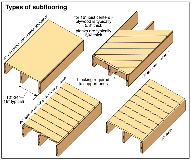 0333
0333Types of subflooring
· p. 56
Four cutaway floor assemblies illustrate sheet subflooring, tongue-and-groove planks, diagonal planks, and plain planks supported by wood joists. The sheet option is labeled plywood or waferboard, with joist spacing indicated as 12–24 inches, typically 16 inches. An annotation states that plywood is typically 5/8 inch thick for joists at 16-inch centers and that planks are typically 3/4 inch thick. The diagonal plank assembly includes blocking to support the plank ends. The other plank assemblies show boards running perpendicular to the joists, with interlocking edges illustrated on the tongue-and-groove version.
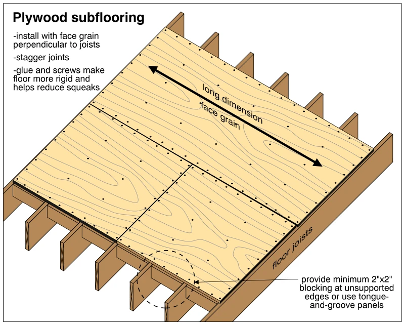 0334
0334Plywood subflooring
· p. 56
The illustration shows plywood subfloor panels installed over parallel wood floor joists, with staggered panel joints. The panels' long dimension and face grain run perpendicular to the joists, as indicated by a double-headed arrow. Fasteners are shown along panel edges and at intermediate supports. A highlighted edge detail calls for minimum 2-inch-by-2-inch blocking at unsupported edges or the use of tongue-and-groove panels. An annotation recommends glue and screws to increase floor rigidity and reduce squeaks.
Floors ·Concrete Floor Slabsp. 57
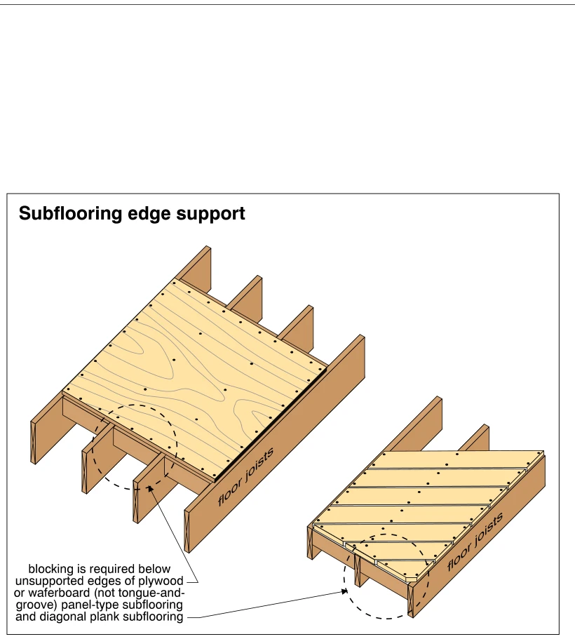 0335
0335Subflooring edge support
· p. 57
Two perspective drawings show subflooring supported by wood floor joists. The left assembly uses panel-type subflooring, while the right uses diagonal plank subflooring. Dashed circles and arrows highlight blocking between joists beneath the subfloor edges. The annotation specifies that blocking is required below unsupported edges of plywood or waferboard panels without tongue-and-groove joints and below diagonal plank subflooring edges.
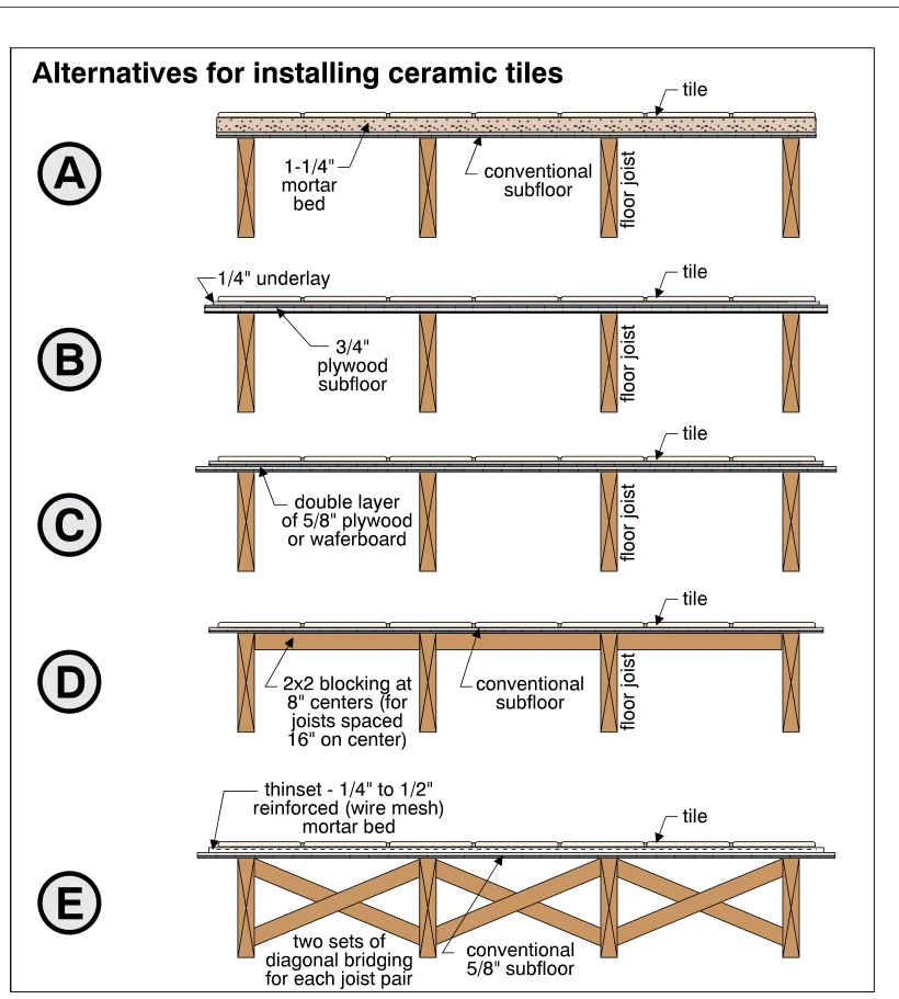 0336
0336Alternatives for installing ceramic tiles
· p. 57
Five cross-sectional diagrams show alternative ceramic tile floor assemblies supported by wood floor joists. Option A uses a 1-1/4-inch mortar bed over a conventional subfloor, while option B uses 1/4-inch underlay over a 3/4-inch plywood subfloor. Option C shows a double layer of 5/8-inch plywood or waferboard beneath the tile. Option D adds 2x2 blocking at 8-inch centers beneath a conventional subfloor for joists spaced 16 inches on center. Option E combines a 1/4- to 1/2-inch wire-mesh-reinforced mortar bed, a conventional 5/8-inch subfloor, and two sets of diagonal bridging for each joist pair.
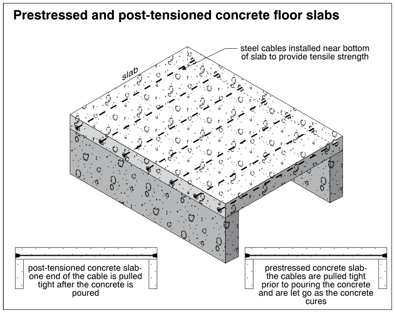 0337
0337Prestressed and post-tensioned concrete floor slabs
· p. 57
The illustration shows a concrete floor slab spanning between concrete supports, with parallel steel cables located near the bottom of the slab to provide tensile strength. Dashed lines indicate the cable paths within the slab. Two smaller sectional diagrams explain the difference in tensioning sequence. The post-tensioned example has one end of the cable pulled tight after the concrete is poured, while the prestressed example has cables pulled tight before pouring and released as the concrete cures.
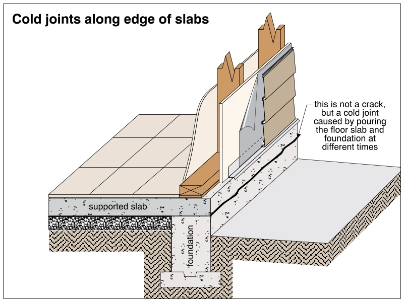 0338
0338Cold joints along edge of slabs
· p. 57
The cutaway shows a supported concrete floor slab meeting a concrete foundation wall and footing beneath a wood-framed exterior wall. The slab rests over a granular layer and soil, with its edge supported by the foundation. An irregular dark line along the exposed slab-to-foundation interface is identified as a cold joint rather than a crack. The annotation explains that this joint results from pouring the floor slab and foundation at different times.
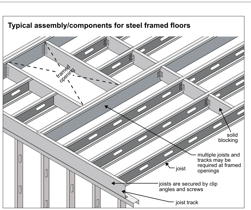 0338.1
Typical assembly/components for steel framed floors
· p. 58
The illustration shows a steel-framed floor assembly supported above steel wall framing, with parallel channel-shaped joists terminating at a perimeter joist track. The joist webs contain elongated openings, and solid blocking spans between selected joists. Clip angles and screws secure the framing connections. A framed floor opening interrupts the joist layout, with an annotation noting that multiple joists and tracks may be required around openings. No damaged or improper conditions are depicted.
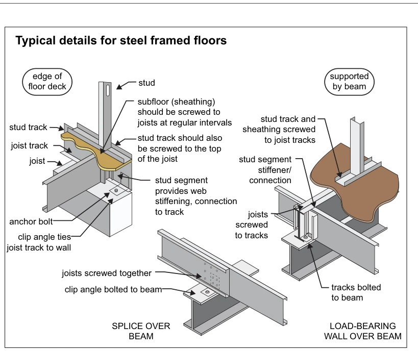 0338.2
Typical details for steel framed floors
· p. 58
Three cutaway details show connections for steel-framed floors at a floor-deck edge, a splice over a beam, and a load-bearing wall over a beam. At the floor edge, a clip angle and anchor bolt tie the joist track to the supporting wall, while a stud segment stiffens the joist web and connects it to the track. Notes specify screwing the subfloor sheathing to the joists at regular intervals and the stud track to the top of the joist. The splice detail shows joists screwed together with a clip angle bolted to the supporting beam. The load-bearing wall detail shows stud-segment stiffeners, joists screwed to tracks, tracks bolted to the beam, and the stud track and sheathing screwed to the joist tracks.
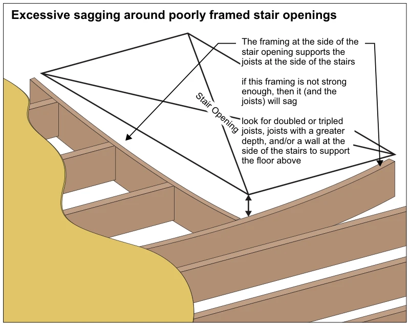 0338.3
Excessive sagging around poorly framed stair openings
· p. 58
A cutaway perspective shows wood floor joists and framing bordering a stair opening, with part of the floor surface removed to expose the structure. Joists beside the opening bear into the bordering framing, which must carry their loads. Reference lines and a vertical double-headed arrow illustrate sagging below the intended floor plane. The annotations identify inadequate framing strength as the cause and advise looking for doubled or tripled joists, deeper joists, or a supporting wall beside the stairs.
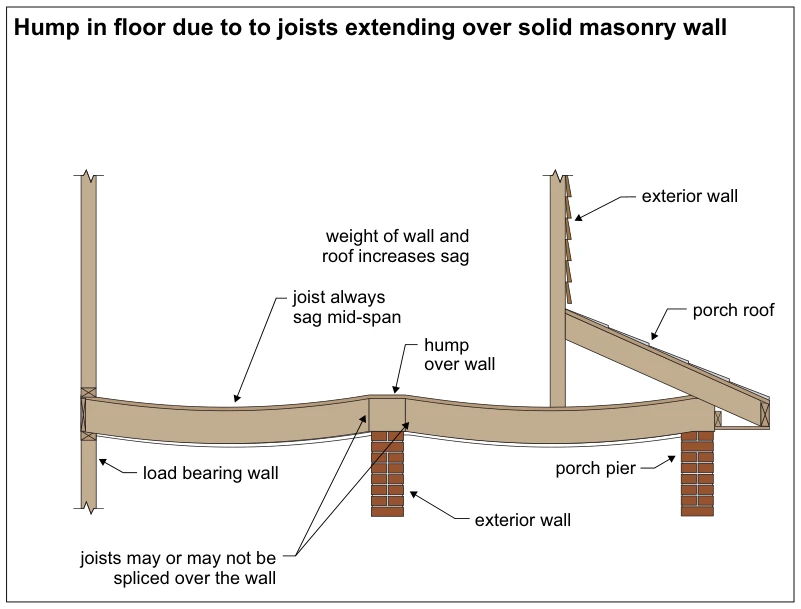 0338.4
Hump in floor due to to joists extending over solid masonry wall
· p. 58
The illustration shows floor joists extending from a load-bearing wall across a solid masonry exterior wall to a porch pier. The joists sag between supports, leaving a relative hump in the floor over the masonry wall. An exterior wall and sloping porch roof impose additional weight on the outer span, increasing its sag. The annotation notes that the joists may or may not be spliced over the masonry wall.
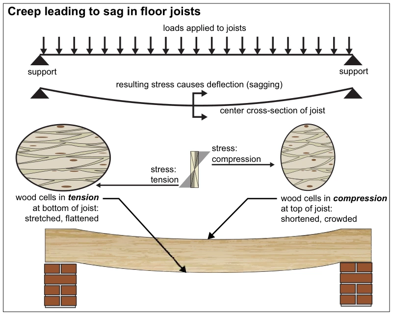 0338.5
Creep leading to sag in floor joists
· p. 58
The illustration explains creep leading to sag in a wood floor joist spanning between two end supports. Downward load arrows are shown above a straight joist diagram, followed by a deflected profile with the greatest sag near midspan. A center cross-section identifies compression at the top and tension at the bottom. Magnified wood-cell diagrams show shortened, crowded cells in compression and stretched, flattened cells in tension. The lower drawing shows a sagging wood joist bearing on brick supports.
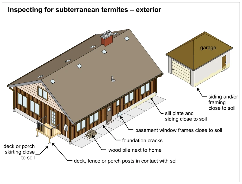 0338.6
Inspecting for subterranean termites – exterior
· p. 58
The illustration shows a house and detached garage with exterior conditions to check when inspecting for subterranean termites. Arrows identify sill plates, siding, framing, basement window frames, and porch skirting positioned close to soil. Other callouts identify foundation cracks, a wood pile beside the house, and deck, fence, or porch posts in contact with soil. These conditions provide potential termite access or conducive conditions; no termites or termite damage are explicitly shown.
Walls ·Solid Masonry Wallsp. 59
 0338.7
Inspecting for subterranean termites – interior
· p. 59
Six schematic details illustrate interior inspection locations and potential entry routes for subterranean termites. Dashed arrows trace routes through or along brick, hollow-block, and stone foundation assemblies toward wood floor framing. Another detail shows termites approaching the base of a wood support post at the basement floor and footing. A basement stair detail identifies wood blocking beneath stairs that pass through the basement floor as another inspection location. The drawings emphasize concealed access at masonry cavities, floor penetrations, and wood-to-foundation interfaces rather than showing specific visible wood damage.
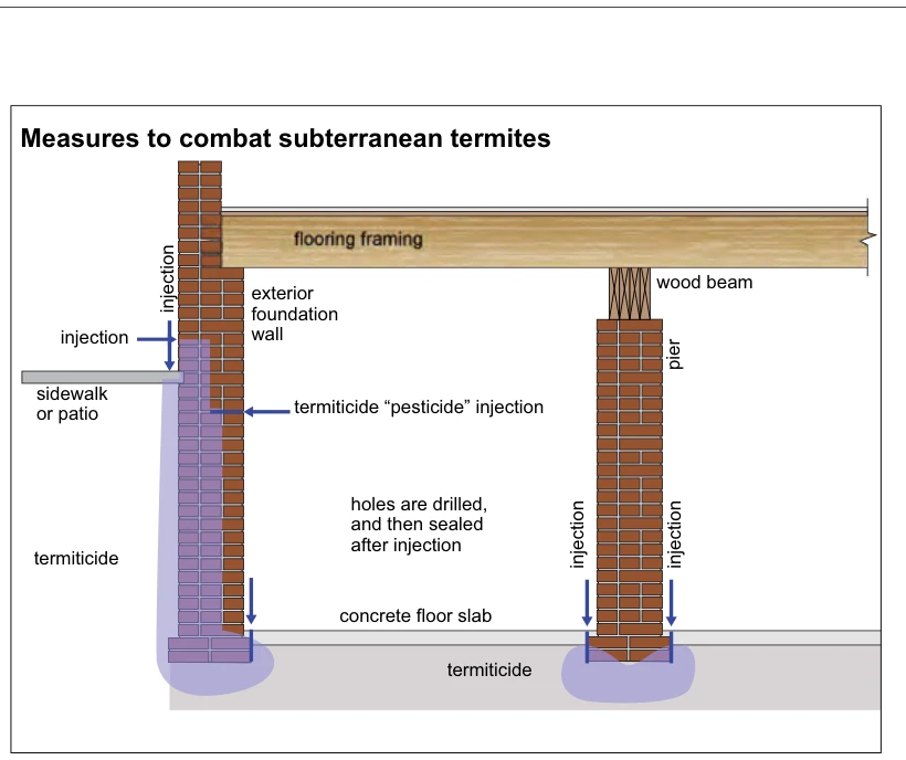 0338.8
Measures to combat subterranean termites
· p. 59
The cross-section shows wood floor framing supported at an exterior masonry foundation wall and by a wood beam bearing on a masonry pier. A concrete floor slab meets the foundation wall and surrounds the pier, with a sidewalk or patio outside. Arrows indicate termiticide injection locations along the exterior foundation and through the slab near the foundation wall and pier. Shaded zones show treatment along the outside of the foundation and beneath the wall and pier bases. An annotation specifies that holes are drilled and then sealed after injection.
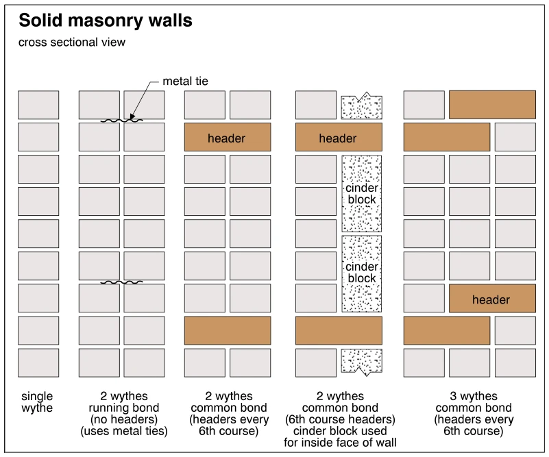 0339
0339Solid masonry walls
· p. 59
Five schematic cross sections show solid masonry walls with one, two, or three wythes. The single-wythe wall is shown beside a two-wythe running-bond wall whose wythes are connected by metal ties rather than headers. A two-wythe common-bond brick wall uses headers every sixth course to connect the wythes. Another two-wythe common-bond wall uses cinder block for its inside face and brick headers at sixth-course intervals. The three-wythe common-bond wall shows headers spanning adjacent wythes at offset courses.
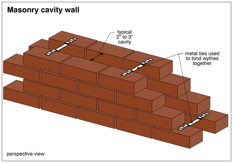 0340
0340Masonry cavity wall
· p. 59
The perspective drawing shows a masonry cavity wall consisting of two parallel brick wythes separated by an air space. The cavity is labeled as typically 2 to 3 inches wide. Metal ties span the cavity and engage both wythes to bind them together. Stepped-back brick courses expose the cavity and ties at different locations. No defects or improper practices are depicted.
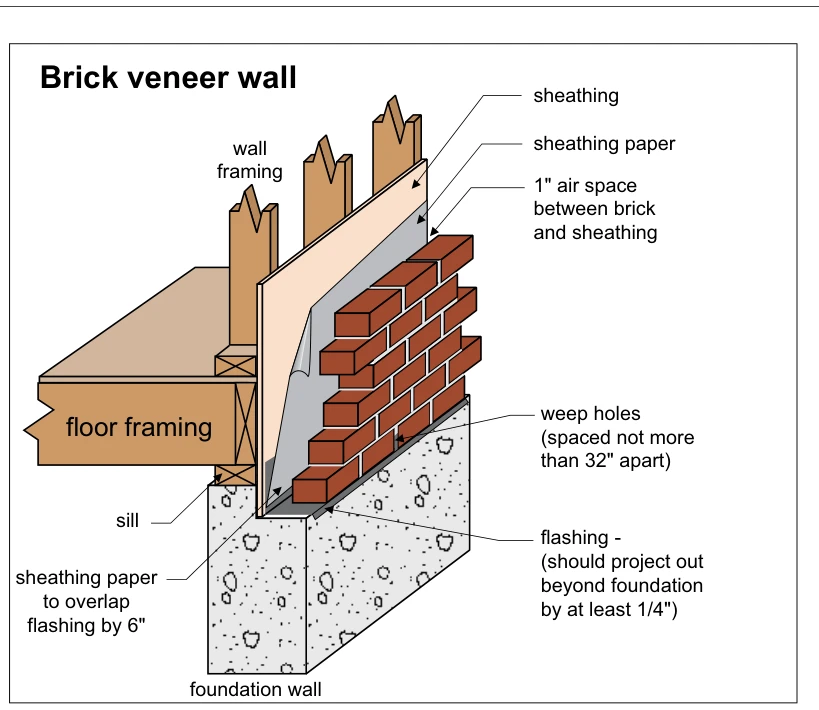 0341
0341Brick veneer wall
· p. 60
The cutaway shows a brick veneer wall outside a framed wall with sheathing and sheathing paper, supported at a concrete foundation wall. A labeled 1-inch air space separates the brick from the sheathing. Base flashing directs cavity water outward through weep holes, which are labeled as spaced not more than 32 inches apart. The sheathing paper is specified to overlap the flashing by 6 inches, and the flashing should project at least 1/4 inch beyond the foundation. Floor framing and a sill are shown on the interior side of the assembly.
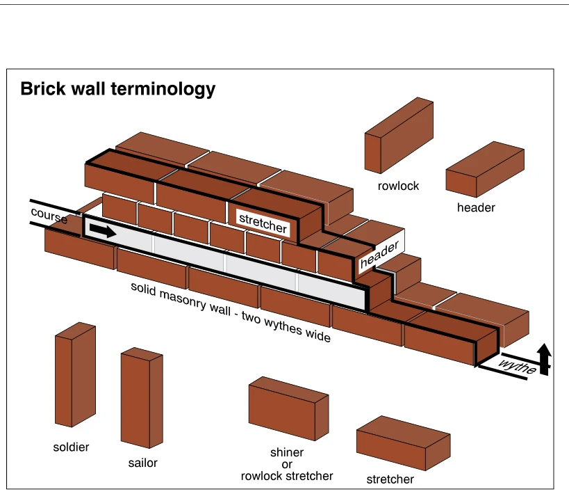 0342
0342Brick wall terminology
· p. 60
The illustration shows a stepped portion of a solid brick masonry wall identified as two wythes wide. Arrows and heavy outlines identify a horizontal course and a wythe, while face labels distinguish stretcher and header bricks in the wall. Separate brick diagrams show the orientations termed rowlock, header, soldier, sailor, shiner or rowlock stretcher, and stretcher. The drawing explains masonry terminology rather than depicting a defect or comparing installation practices.
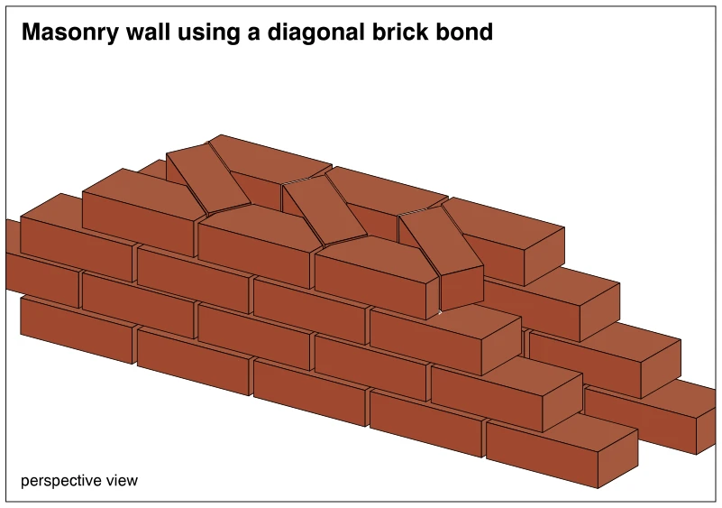 0343
0343Masonry wall using a diagonal brick bond
· p. 60
The perspective drawing shows a solid brick masonry wall with parallel wythes laid in staggered courses. Portions of the upper courses are omitted to expose the wall's internal bonding arrangement. Diagonally oriented bricks cross between the wythes, connecting the parallel rows of masonry. The illustration explains a diagonal brick bond rather than depicting a defect.
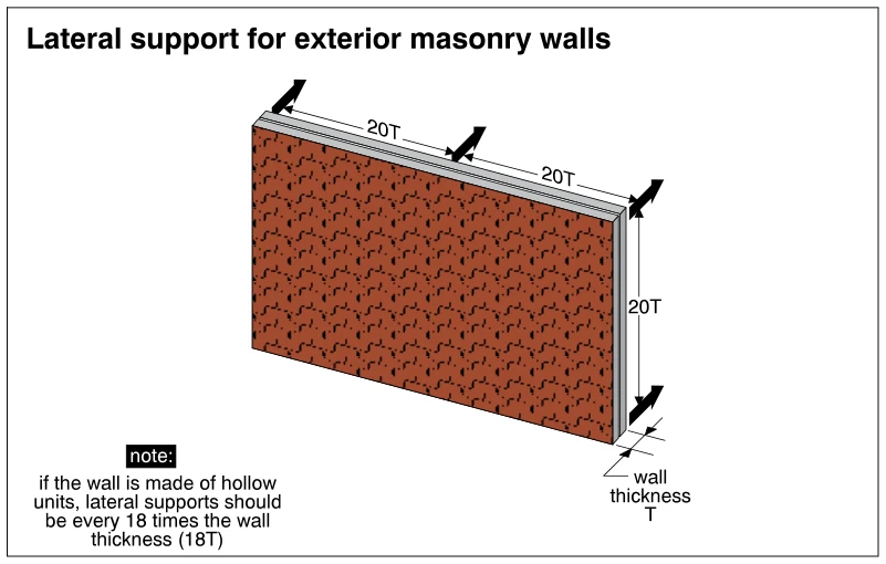 0344
0344Lateral support for exterior masonry walls
· p. 60
The illustration shows an exterior masonry wall panel in perspective, with its thickness identified as T. Heavy arrows indicate lateral support locations along the top and right edge of the wall. Dimension lines identify horizontal and vertical support spacing as 20 times the wall thickness (20T). A note specifies that walls made of hollow units should have lateral supports every 18 times the wall thickness (18T). No specific support connections or defects are depicted.
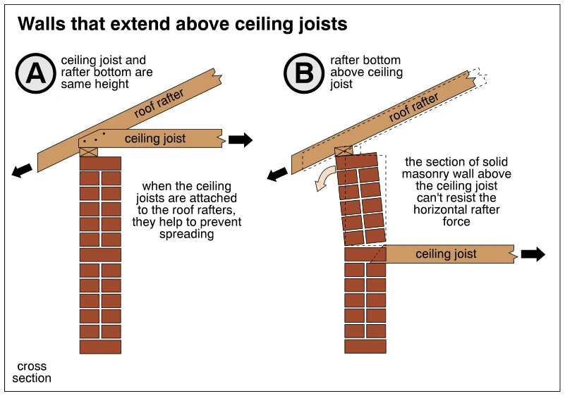 0345
0345Walls that extend above ceiling joists
· p. 60
Two cross sections compare roof rafter and ceiling joist connections at solid masonry walls. In A, the ceiling joist and rafter bottom are at the same height, and the joist is attached directly to the rafter to help prevent spreading. In B, the masonry wall extends above the ceiling joist, with the rafter bearing at the top of this raised section. The upper masonry is shown tilting outward under horizontal rafter thrust, with dashed outlines and arrows indicating displacement and force.
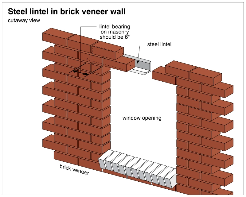 0346
0346Steel lintel in brick veneer wall
· p. 60
The cutaway illustrates a window opening in a brick veneer wall with an angle-shaped steel lintel at the head. The exposed lintel has a horizontal leg supporting the brickwork above the opening and a vertical leg behind it. An annotation specifies that lintel bearing on the masonry should be 6 inches. Brick jambs flank the opening, and a row of angled masonry sill units runs along its bottom.
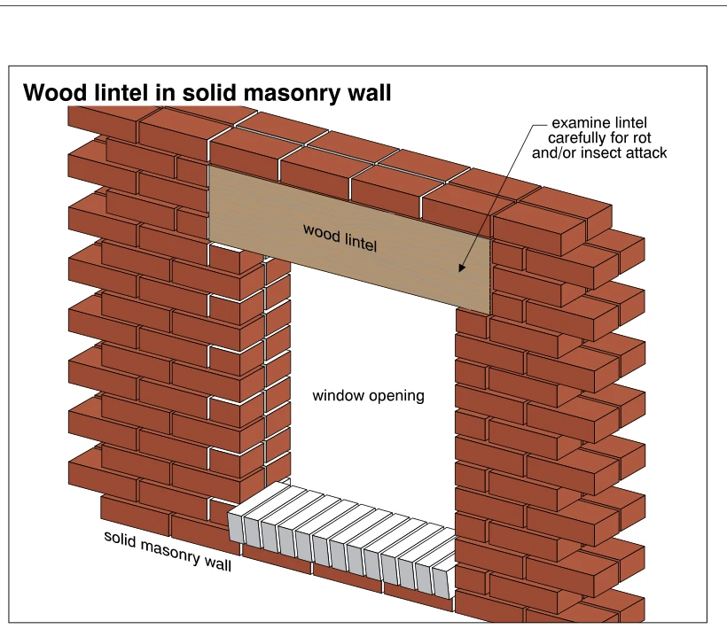 0347
0347Wood lintel in solid masonry wall
· p. 61
The illustration shows a window opening in a solid brick masonry wall. A wood lintel spans the head of the opening, bearing on masonry at each end and supporting the brickwork above. A row of masonry units forms the sill at the bottom of the opening. An arrow directs the inspector to examine the wood lintel carefully for rot and/or insect attack; no actual deterioration is illustrated.
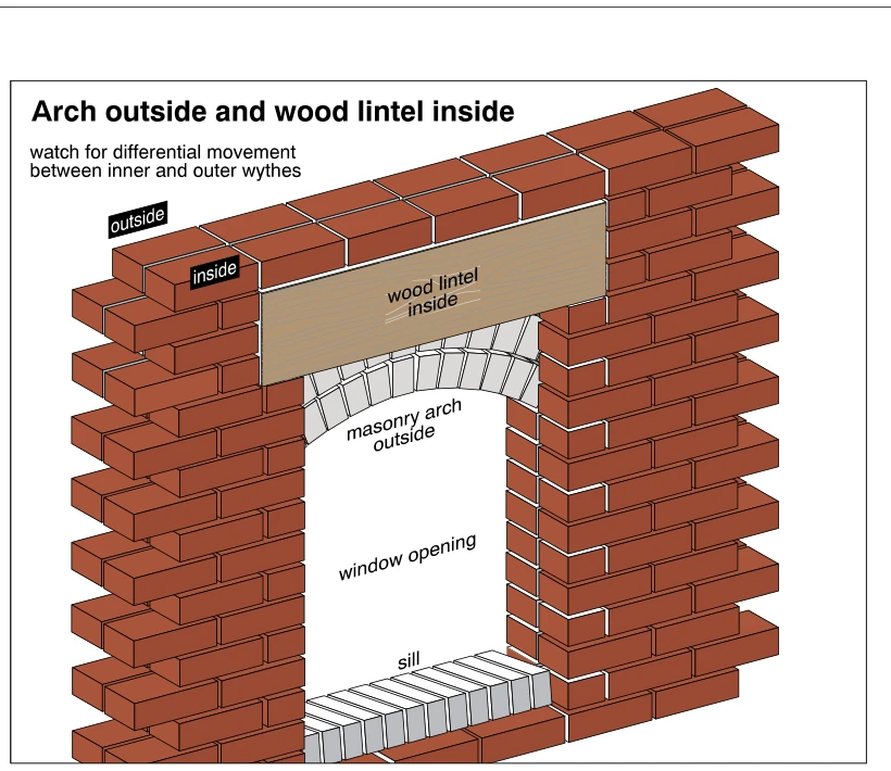 0348
0348Arch outside and wood lintel inside
· p. 61
The illustration shows a window opening in a multiwythe solid brick masonry wall. A horizontal wood lintel spans the opening at the inner wythe, while a masonry arch supports the outer wythe above the opening. Both supports bear on the masonry at the sides of the opening, and a masonry sill spans its base. An annotation advises watching for differential movement between the inner and outer wythes; no actual damage is depicted.
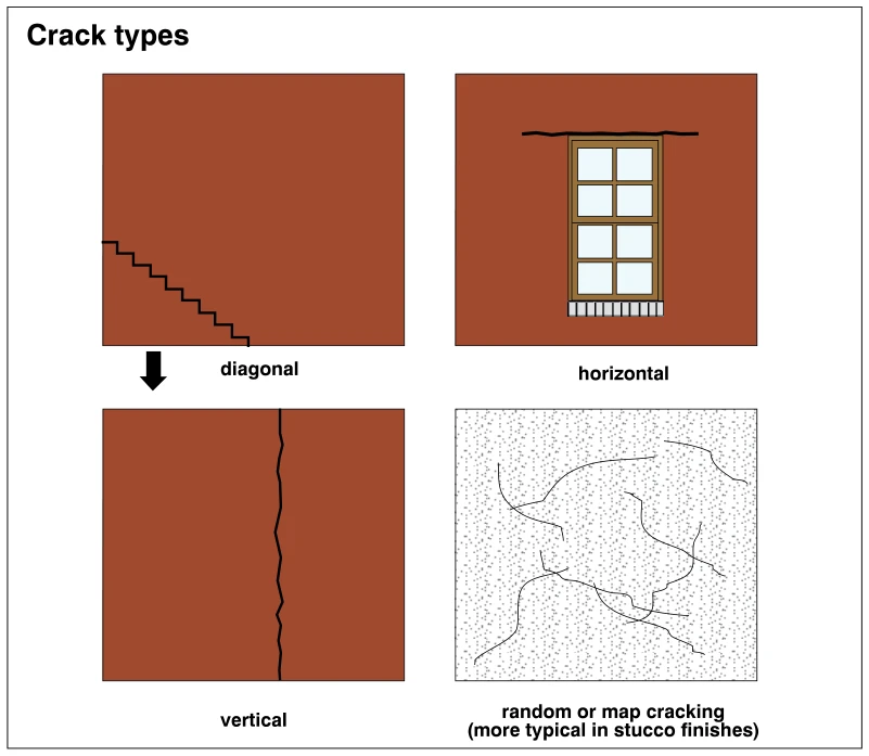 0349
0349Crack types
· p. 61
The illustration presents four wall crack patterns in separate panels. A diagonal crack follows a stair-step path across the lower portion of a masonry wall, while a horizontal crack extends above a window opening. A vertical crack runs nearly the full height of another wall panel. The final panel shows irregular, branching random or map cracking in a textured surface, identified as more typical in stucco finishes. A downward arrow appears between the two left-hand panels.
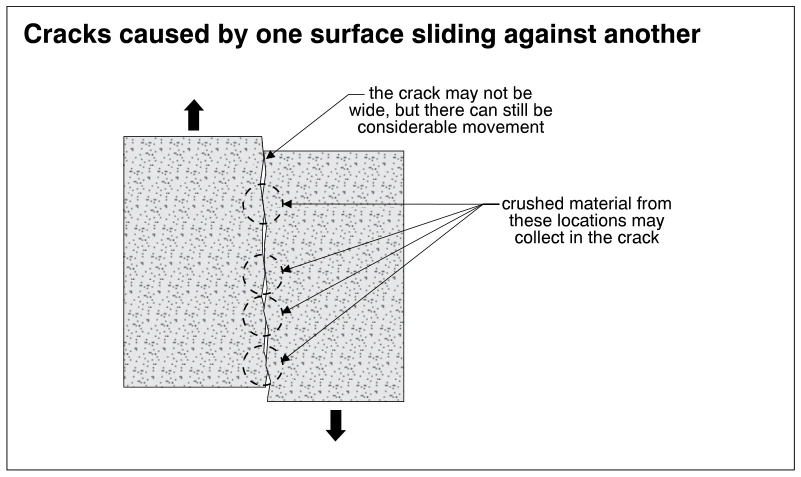 0350
0350Cracks caused by one surface sliding against another
· p. 61
The illustration shows two portions of a solid masonry wall separated by a narrow, irregular vertical crack. Opposing arrows indicate the left portion moving upward relative to the right portion, which moves downward. Dashed circles highlight locations along the crack where sliding contact crushes material that may collect in the crack. The drawing emphasizes that considerable movement can occur even when the crack is not wide.
 0351
0351Cracking - planes of movement
· p. 61
The illustration shows a masonry-walled building with a hip roof and cracking around the base of an exterior corner. A prominent crack extends across both adjoining wall faces, separating a lower corner section from the wall above. Arrows indicate that this section is dropping and rotating outward, demonstrating movement in two different planes. Additional thinner cracks extend into the adjacent wall areas. The annotation states that movement in more planes generally indicates a more serious problem.
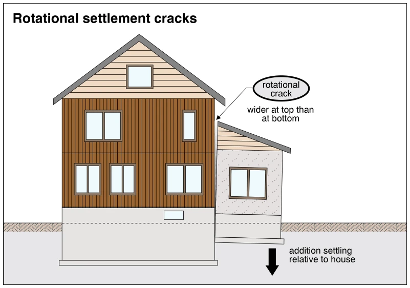 0352
0352Rotational settlement cracks
· p. 61
The illustration shows a two-story house with a smaller, single-story addition on a separate foundation. The addition is tilted away from the main house, with a downward arrow indicating settlement relative to the house. A separation at the junction between the two structures is wider at the top than at the bottom and is identified as a rotational crack. The foundation and footing of the addition are also drawn sloping relative to those of the main house.
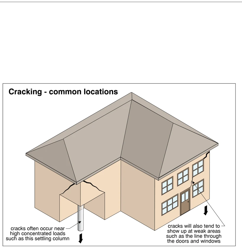 0353
0353Cracking - common locations
· p. 62
The illustration shows a two-story masonry house with a hip roof and a cutaway exposing a supporting column beneath a wall corner. Cracks extend diagonally through the masonry above the column, where a downward arrow indicates settlement under a concentrated load. On the other elevation, cracking follows a weakened line through door and window openings, with another downward arrow indicating movement. The drawing identifies common masonry cracking locations associated with concentrated loads and wall openings.
 0354
0354Roof truss uplift
· p. 62
Two cross sections illustrate uplift of a wood roof truss above a central interior wall. The upper drawing shows insulation around the bottom chord and arrows indicating expansion of colder, wetter wood and shrinkage of warmer, drier wood. The lower drawing shows the bottom chord bowed upward at the center, with insulation omitted for clarity. Cracks are indicated at the central wall-to-ceiling intersections where the truss lifts away from the wall.
 0355
0355Garage settlement
· p. 62
The illustration shows a two-story house with a basement foundation and an attached single-story garage with a shed roof. The garage is depicted settling downward relative to the house, with its wall, door opening, and footing tilted. A callout identifies a settlement crack at the junction between the garage and house near the garage roof. An annotation notes that settlement is often rotational, and a downward arrow emphasizes the garage's movement.
 0356
0356Lintel related wall cracks
· p. 62
Two brick masonry wall elevations show lintel-related cracking above window openings. The left elevation depicts stair-step cracks in the mortar joints above the window, identified as a pattern commonly associated with lintels sagging due to undersizing or deterioration. An arrow identifies the lintel at the window head, and the window sill is labeled below. The right elevation shows a horizontal crack along the window-head level extending beyond the opening, identified as a condition often caused by expanding, rusting steel lintels.
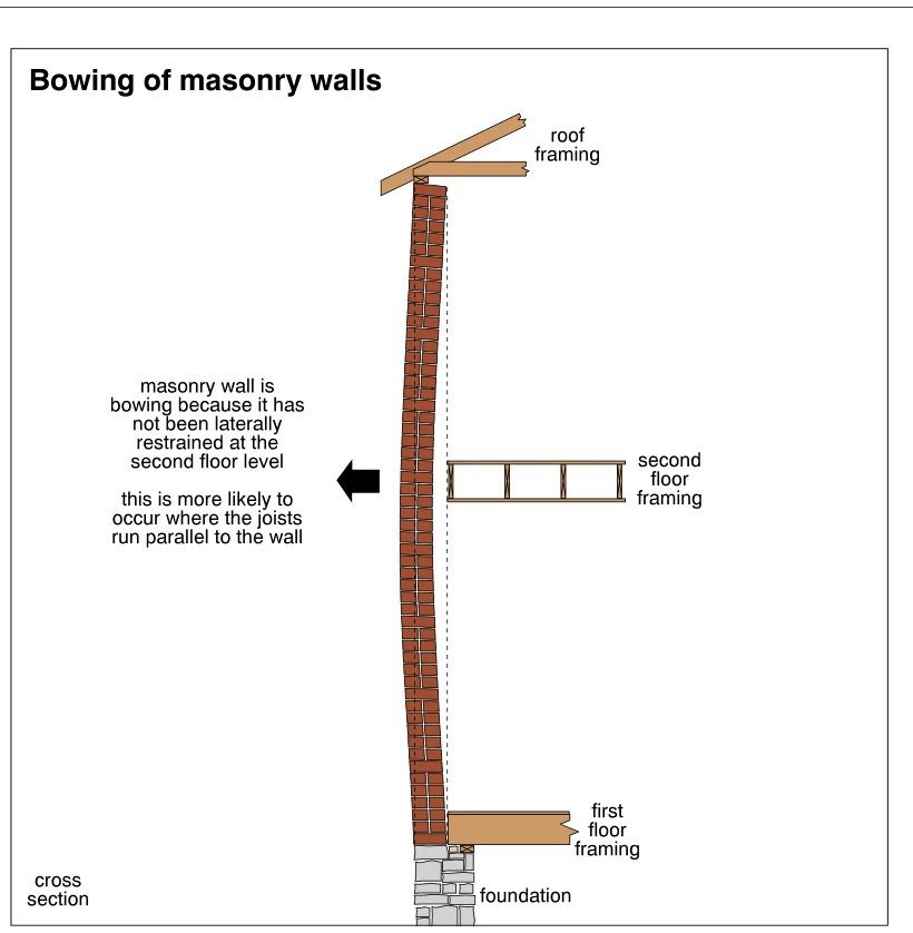 0357
0357Bowing of masonry walls
· p. 63
The cross section depicts a solid masonry wall extending from a foundation to wood roof framing, with first- and second-floor framing on the interior side. The wall bows outward, with its greatest displacement near the second-floor level; a dashed vertical reference line highlights the deviation. An arrow indicates the outward movement. The annotation attributes the bowing to a lack of lateral restraint at the second floor and notes that this is more likely where joists run parallel to the wall.
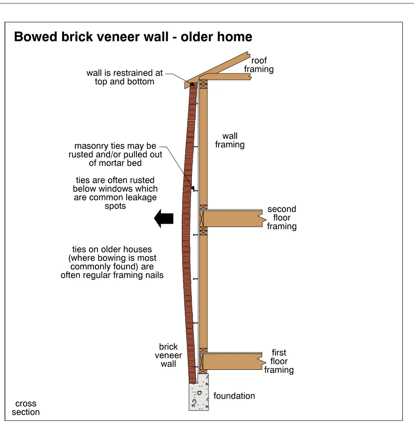 0358
0358Bowed brick veneer wall - older home
· p. 63
The cross section shows a brick veneer wall bowing outward away from the wood-framed wall of an older home. The veneer remains restrained at its top near the roof and at its bottom on the foundation, while an arrow indicates outward displacement near mid-height. Masonry ties connect the veneer to the framing, with annotations identifying rusting and withdrawal from the mortar bed as possible causes of lost restraint. Notes identify leakage below windows as a common source of tie corrosion and regular framing nails as ties often found in older houses. First- and second-floor framing and roof framing are shown attached to the wall framing.
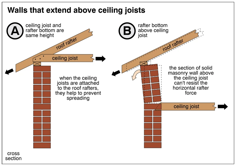 0359
0359Walls that extend above ceiling joists
· p. 63
Two cross sections compare roof-rafter and ceiling-joist connections at solid masonry walls. In A, the ceiling joist and rafter bottom are at the same height, and the joist is attached directly to the rafter to help prevent spreading. In B, the masonry wall extends above the ceiling joist, with the rafter bearing at the top of the raised wall section. The upper masonry section is shown tilting outward relative to a dashed upright outline, illustrating its inability to resist horizontal rafter thrust. Arrows indicate the horizontal forces and outward movement.
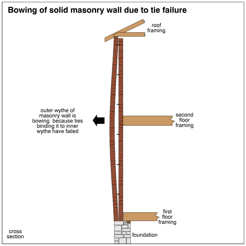 0360
0360Bowing of solid masonry wall due to tie failure
· p. 63
The cross section shows a two-wythe solid masonry wall extending from a foundation to roof framing, with first- and second-floor framing on the interior side. The inner wythe remains straight while the outer wythe bows outward, with its greatest displacement near the second-floor level. An outward-pointing arrow emphasizes the displacement. The annotation attributes the bowing to failure of the ties binding the outer wythe to the inner wythe.
 0361
0361Cracks due to clay brick expansion
· p. 64
The illustration shows two intersecting clay brick masonry walls supported on a foundation wall, with three windows in the longer wall. A vertical crack near the corner is identified as resulting from the long wall expanding and pushing past the end wall. Horizontal cracks extend around the window openings in the longer wall and are also attributed to clay brick expansion. The drawing illustrates expansion-related distress in solid masonry walls.
 0362
0362Using rods and channels to stabilize a settled house
· p. 64
The illustration shows a masonry house with differential settlement at the right side, where unstable soil lies beneath the foundation. A large irregular crack extends through the foundation wall and continues as stepped cracking through the brick masonry. Two horizontal steel rods pass through the house and are secured at their threaded ends to vertical channels or beams on the outside walls. An annotation identifies steel plates as an alternative for spreading rod-end loads where less support is required. A downward arrow indicates movement of the settled foundation relative to the sound soil.
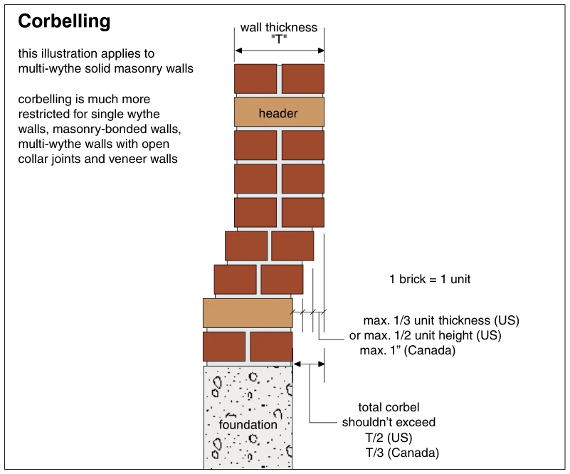 0363
0363Corbelling
· p. 64
The illustration shows a section through a multi-wythe solid brick masonry wall supported on a concrete foundation. Successive masonry courses are offset to form a corbel, shifting the upper wall beyond the foundation edge, with header bricks spanning the wall thickness. Dimension lines identify wall thickness T, individual course projections, and the total corbel projection. Annotations specify maximum individual projections of one-third unit thickness or one-half unit height in the US and 1 inch in Canada, with total projection limited to T/2 in the US and T/3 in Canada. A note states that corbelling is more restricted for single-wythe walls, masonry-bonded walls, multi-wythe walls with open collar joints, and veneer walls.
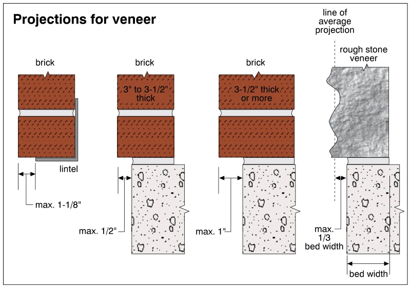 0364
0364Projections for veneer
· p. 64
Four sectional details show maximum permitted projections of masonry veneer beyond its supporting lintel or concrete support. The first detail shows brick bearing on an angle lintel, with a maximum projection of 1-1/8 inches beyond the lintel edge. The next two details show brick projecting beyond concrete supports: a maximum of 1/2 inch for brick 3 to 3-1/2 inches thick, and 1 inch for brick 3-1/2 inches thick or more. The final detail shows rough stone veneer with its irregular outer face referenced to a line of average projection, limiting the overhang to one-third of the bed width.
Walls ·Wood Frame Wallsp. 65
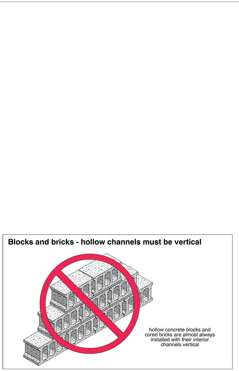 0365
0365Blocks and bricks - hollow channels must be vertical
· p. 65
The illustration shows a stepped section of hollow masonry wall with staggered joints between units. The units are laid with their hollow channels running horizontally, exposing the openings on the wall face. A large red prohibition symbol marks this orientation as incorrect. The annotation states that hollow concrete blocks and cored bricks are almost always installed with their interior channels vertical.
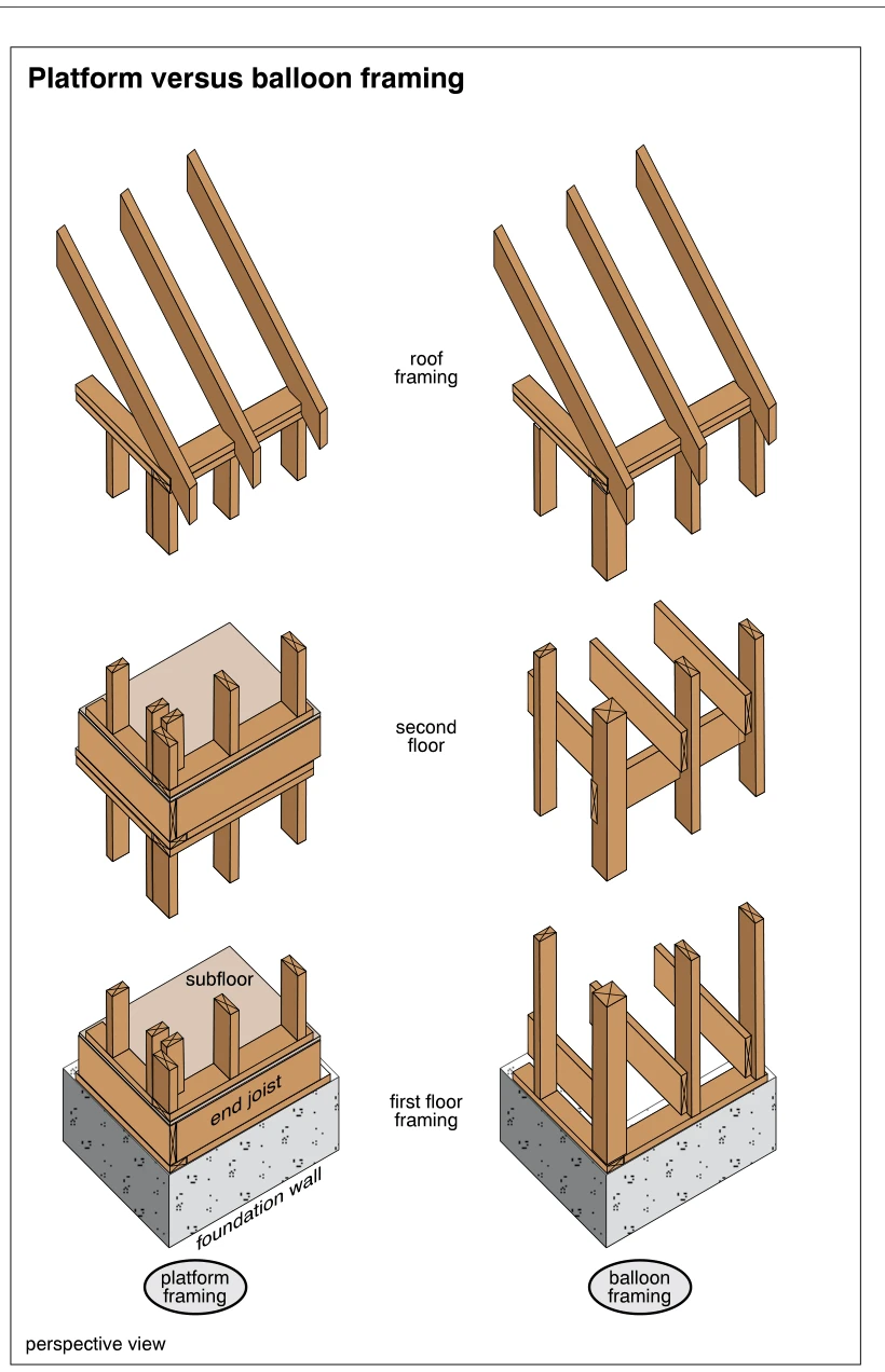 0366
0366Platform versus balloon framing
· p. 65
Two exploded perspective views compare platform framing on the left with balloon framing on the right, from the foundation wall to the roof framing. The platform-framed assembly shows separate story-height studs bearing on floor platforms, with subfloor panels over the floor framing and end joists enclosing the edges. The balloon-framed assembly shows studs extending past the second-floor framing, with floor joists supported alongside the studs rather than by a separate wall-top platform. Both assemblies include wood wall plates and sloping roof rafters. No defects are identified.
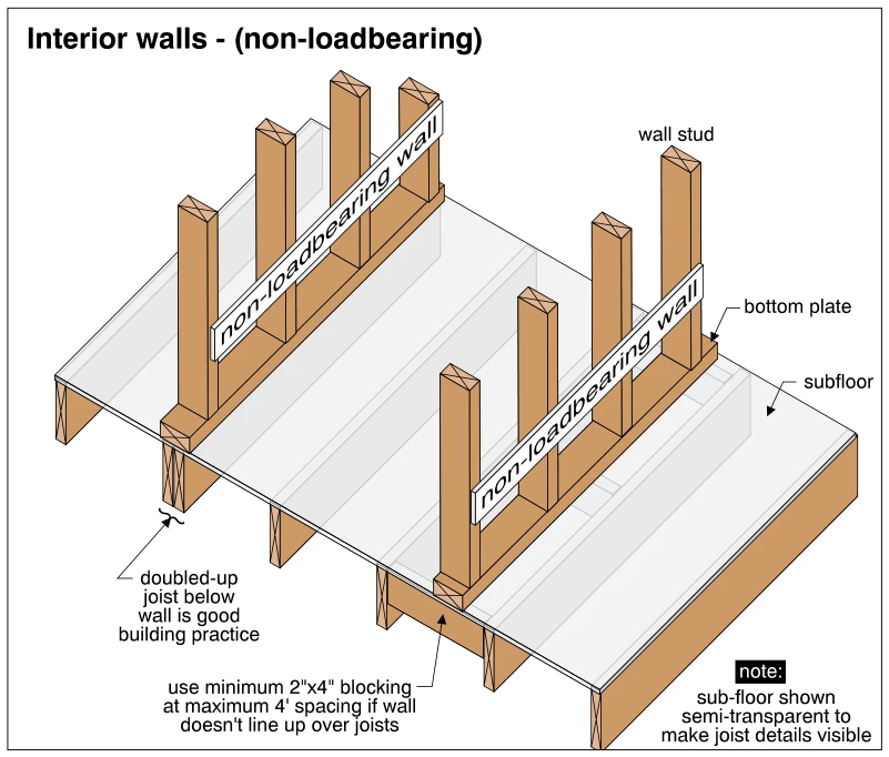 0367
0367Interior walls - (non-loadbearing)
· p. 65
The illustration shows two non-loadbearing wood-stud interior walls resting on bottom plates over a wood-framed floor. The subfloor is drawn semi-transparent to reveal the floor joists and blocking beneath the walls. One wall is aligned over a doubled-up joist, identified as good building practice. The other wall lies between joists, with an annotation specifying minimum 2"x4" blocking at maximum 4-foot spacing where the wall does not line up over joists.
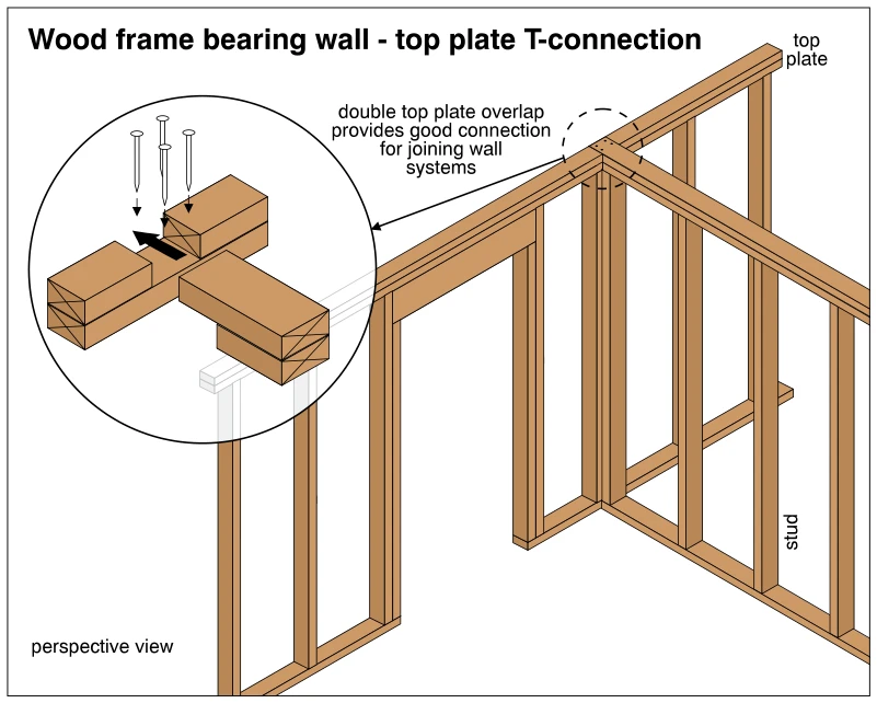 0368
0368Wood frame bearing wall - top plate T-connection
· p. 65
The illustration shows two wood-frame bearing walls meeting at a T-intersection, with vertical studs between bottom plates and double top plates. The double top plates overlap at the intersection to tie the wall systems together. A circular enlarged detail shows the staggered plate ends and nails used to fasten the overlapping connection. This depicts a proper framing connection rather than a defect.
 0369
0369Holes and notches in top plates of bearing walls
· p. 66
A perspective drawing shows intersecting wood-framed bearing walls with double top plates, vertical studs, bottom plates, and a framed opening. A circular enlargement shows a drilled hole and an edge notch in the double top plate. Dimension arrows indicate 2 inches of remaining material beside the cuts. The annotation states that holes or notches must leave 2 inches of material intact or the top plate should be reinforced.
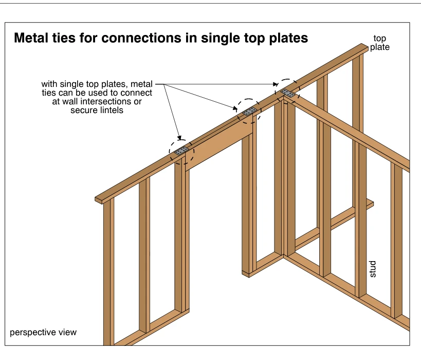 0370
0370Metal ties for connections in single top plates
· p. 66
A perspective drawing shows intersecting wood-framed walls with single top plates and an opening spanned by a lintel. Metal ties bridge connections at both ends of the lintel and at the wall intersection. Arrows and dashed circles highlight these three connection locations. Vertical studs support the horizontal framing, and bottom plates connect the stud bases.
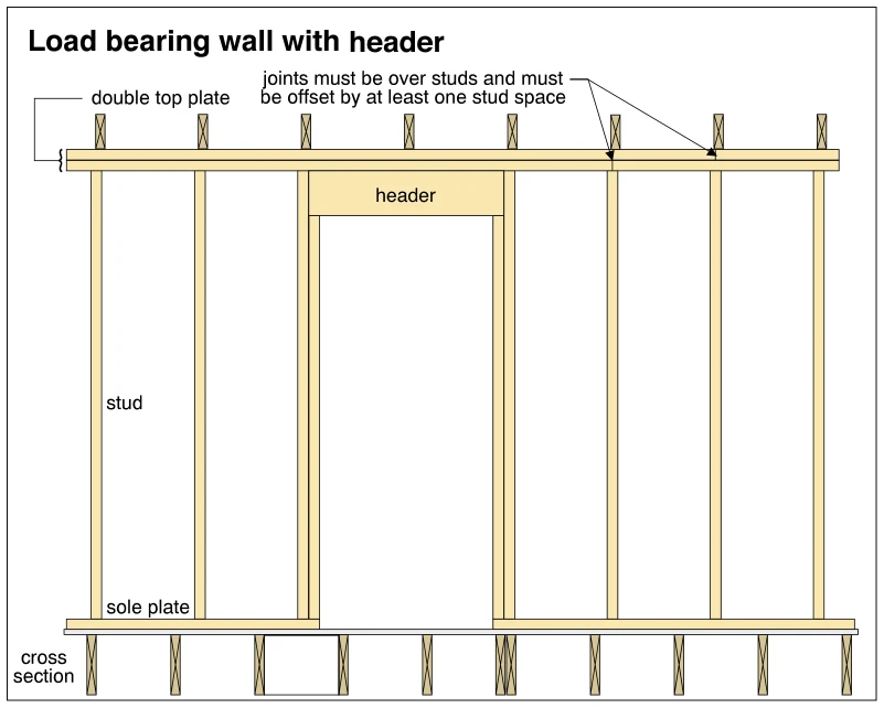 0371
0371Load bearing wall with header
· p. 66
The illustration shows a wood-framed load-bearing wall with a header spanning a tall opening. Shortened jack studs support the header at each end, alongside full-height studs. A double top plate runs across the wall, with its joints located over studs and offset by at least one stud space as annotated. The sole plate runs beneath the wall studs and is interrupted at the opening. Cross sections of framing members are shown above and below the wall.
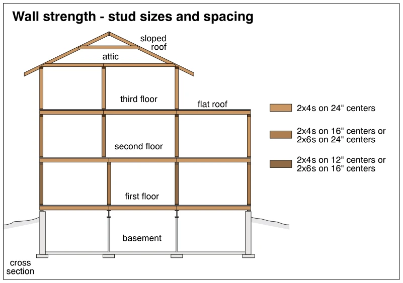 0372
0372Wall strength - stud sizes and spacing
· p. 66
A color-coded building cross section illustrates how wood wall stud sizes and spacing relate to wall strength at different stories. The main portion has three floors beneath an attic and sloped roof, while an adjoining two-story portion has a flat roof. A legend identifies three framing configurations, ranging from 2x4 studs on 24-inch centers to 2x4 studs on 12-inch centers or 2x6 studs on 16-inch centers. The shading indicates stronger framing configurations in lower walls supporting more stories. Basement foundation walls, interior support posts, and footings are also shown.
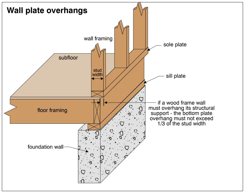 0373
0373Wall plate overhangs
· p. 66
The illustration shows a wood-framed wall supported above floor framing and a concrete foundation wall. Wall studs rest on a sole plate above the subfloor, while a sill plate separates the floor framing from the foundation. The sole plate projects outward beyond its structural support, with arrows identifying the overhang and the stud width. The annotation states that, if a wood-frame wall must overhang its structural support, the bottom plate overhang must not exceed one-third of the stud width.
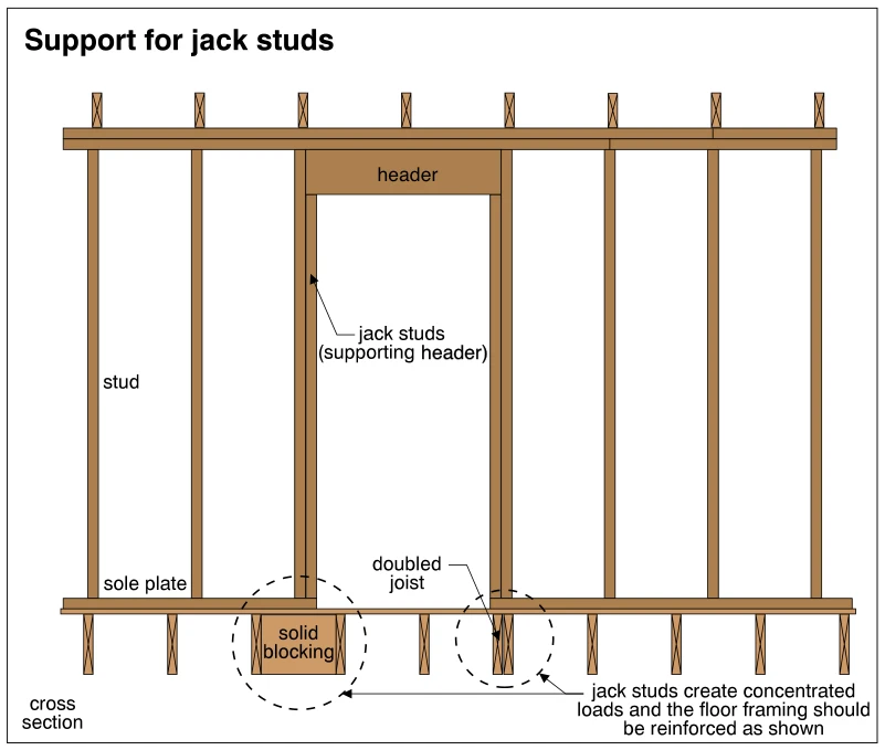 0374
0374Support for jack studs
· p. 66
The illustration shows a cross section of a wood-frame wall with a header spanning an opening. Jack studs at each side of the opening support the header and bear on the sole plate. Dashed circles highlight reinforcement in the floor framing directly beneath the jack studs: solid blocking on the left and a doubled joist on the right. These details provide support for the concentrated loads transferred through the jack studs.
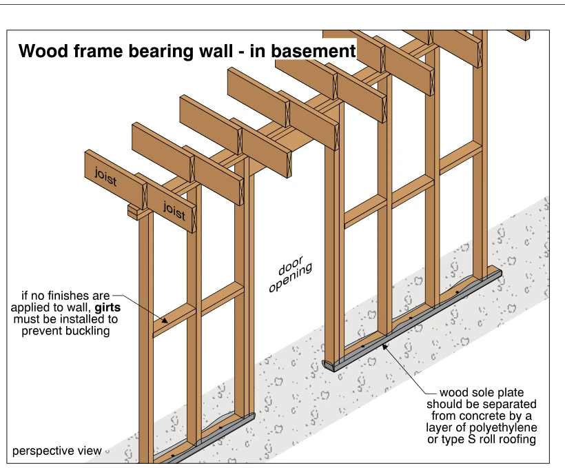 0375
0375Wood frame bearing wall - in basement
· p. 67
The perspective drawing shows a wood-frame basement bearing wall supporting floor joists, with a framed door opening interrupting the wall. Vertical studs bear on a wood sole plate over concrete, and horizontal girts connect the studs between the floor and joists. An annotation specifies that girts must be installed to prevent buckling if no wall finishes are applied. A separate layer beneath the sole plate is identified as polyethylene or type S roll roofing to separate the wood from the concrete.
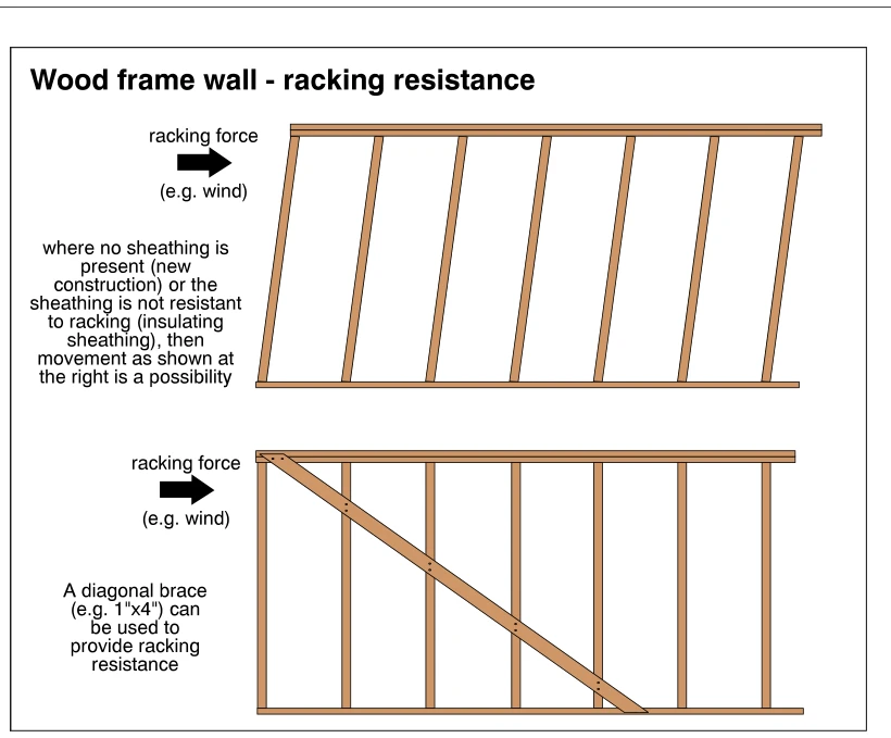 0376
0376Wood frame wall - racking resistance
· p. 67
Two wood stud wall diagrams compare behavior under a horizontal racking force, such as wind. The upper wall is distorted into a parallelogram, with the studs leaning and the top plate displaced relative to the bottom plate. Its annotation explains that this movement is possible when sheathing is absent or does not resist racking. The lower wall remains rectangular and has a diagonal wood brace fastened across the studs from the upper left to the bottom plate, providing racking resistance.
 0377
0377Installing oriented strandboard
· p. 67
The perspective drawing shows oriented strandboard (OSB) sheathing fastened to a wood-framed wall with vertical studs and horizontal plates. The strand direction runs perpendicular to the wall studs. Fasteners are shown along panel edges and intermediate framing lines, and vertical panel joints are staggered between courses. Gaps between adjacent panels accommodate swelling, as noted in the installation guidance. Portions of the framing remain exposed to show the relationship between the sheathing and studs.
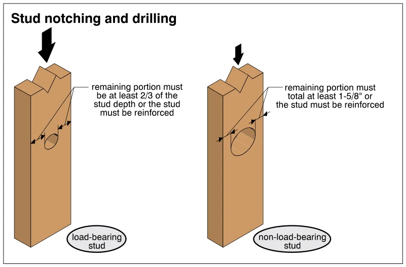 0378
0378Stud notching and drilling
· p. 67
The illustration compares drilled wood studs in load-bearing and non-load-bearing walls. Each stud has a hole through its face, with dimension arrows identifying the remaining wood on either side of the hole. The load-bearing example specifies that the remaining portion must be at least two-thirds of the stud depth or the stud must be reinforced. The non-load-bearing example specifies a total remaining portion of at least 1-5/8 inches or reinforcement is required. Downward arrows above the studs indicate loading, with a larger arrow over the load-bearing example.
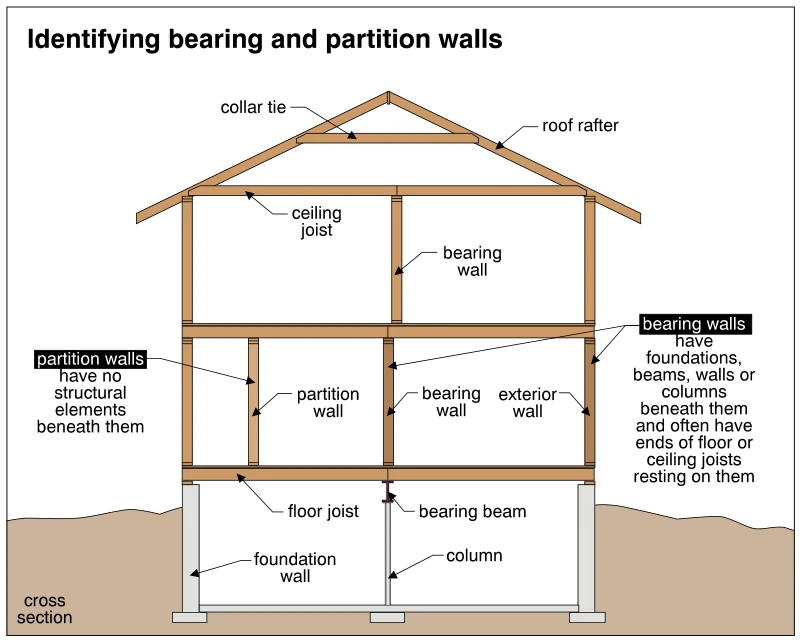 0379
0379Identifying bearing and partition walls
· p. 67
A house cross section illustrates how to distinguish bearing walls from partition walls in wood-frame construction. Sloped roof rafters, a collar tie, and ceiling joists are shown above two framed stories and a basement. Interior bearing walls align vertically over a basement bearing beam and column, while exterior walls rest on foundation walls. A partition wall on the lower framed story has no corresponding structural support directly beneath it. The annotations explain that bearing walls have supporting foundations, beams, walls, or columns below and often support the ends of floor or ceiling joists.
 0380
0380Common rot locations in walls
· p. 67
A perspective cutaway shows a wood-framed wall and floor assembly supported by a foundation wall. Wall studs rest on a sole plate above the subfloor, with an end joist and sill plate below. Dashed outlines highlight rot at the sole plate and the bottoms of the studs. An annotation explains that condensation water runs to the bottom of the wall and causes the most damage in these locations.
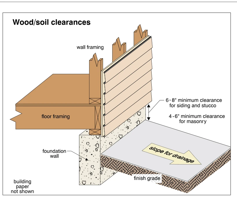 0381
0381Wood/soil clearances
· p. 68
The illustration shows a cutaway of a wood-framed exterior wall and floor supported by a foundation wall, with horizontal lap siding on the exterior. A vertical dimension indicates separation between the bottom of the exterior cladding and finish grade. The annotations specify 6–8 inches minimum clearance for siding and stucco and 4–6 inches for masonry. Finish grade slopes away from the foundation for drainage. Building paper is explicitly noted as not shown.
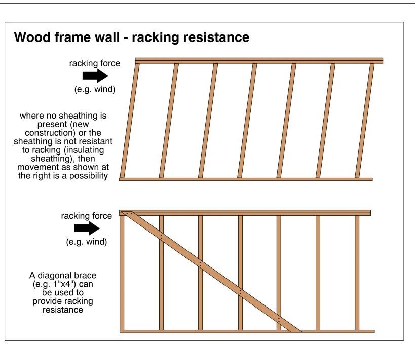 0382
0382Wood frame wall - racking resistance
· p. 68
The illustration compares two wood stud walls subjected to a horizontal racking force, such as wind. The upper wall is distorted into a parallelogram, with its studs leaning as the top moves sideways relative to the bottom plate. An annotation identifies absent sheathing or sheathing without racking resistance as conditions that permit this movement. The lower wall remains rectangular and has a diagonal wood brace extending from the upper-left corner to the bottom plate near the right side, fastened across the studs to provide racking resistance.
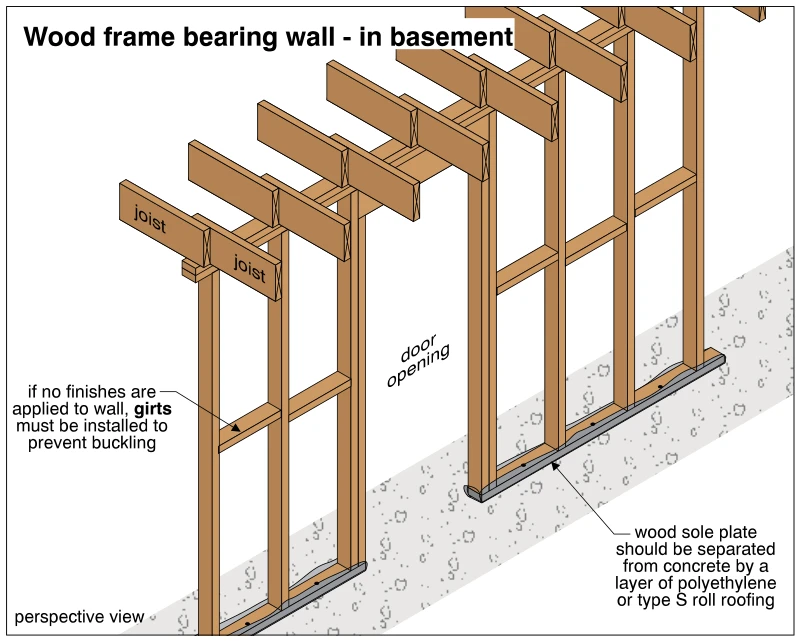 0383
0383Wood frame bearing wall - in basement
· p. 68
The perspective drawing shows a wood-frame basement bearing wall supporting floor joists above. Vertical studs rest on wood sole plates over concrete, with a framed door opening interrupting the wall. Horizontal girts connect the studs; the annotation specifies that girts are needed to prevent buckling if no wall finishes are applied. A separating layer beneath the sole plates is identified as polyethylene or type S roll roofing to isolate the wood from the concrete.
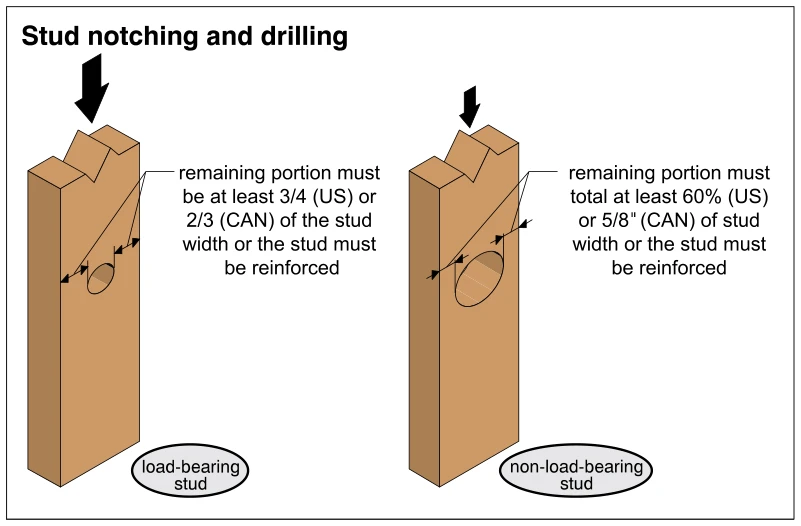 0384
0384Stud notching and drilling
· p. 68
The illustration compares drilling and notching restrictions for load-bearing and non-load-bearing wood studs. Each stud is shown with a drilled hole, dimension arrows indicating the remaining wood on either side, and a downward arrow above it. The load-bearing stud annotation requires at least 3/4 (US) or 2/3 (CAN) of the stud width to remain unless the stud is reinforced. The non-load-bearing stud annotation requires the remaining portions to total at least 60% (US) or 5/8" (CAN) of the stud width unless reinforced. The non-load-bearing example has a visibly larger hole.
 0385
0385Straightening partition studs
· p. 68
The perspective drawing shows intersecting wood-framed walls with vertical studs, top and bottom plates, and horizontal blocking. A dashed circle highlights a stud with a cut near mid-height and a short wood sister fastened alongside it to maintain alignment. The annotation states that straightening a stud is permissible in a partition wall. It cautions that a similar sistered stud may be found in a bearing wall, where this repair is less than ideal.
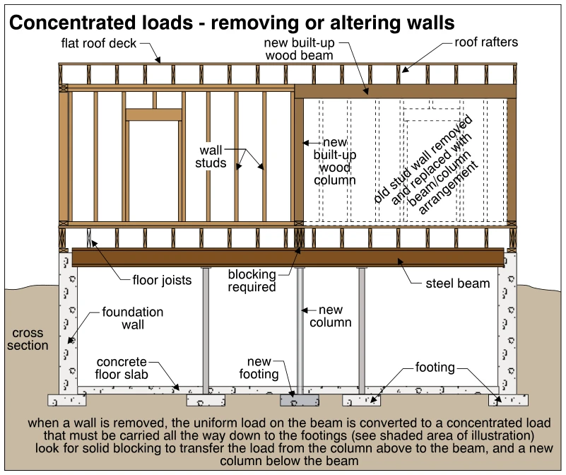 0386
0386Concentrated loads - removing or altering walls
· p. 68
The cross section depicts a wood-frame wall partially removed and replaced with a new built-up wood beam and column beneath flat-roof framing. Dashed outlines indicate the removed wall studs. The highlighted load path runs from the new wood column through solid blocking in the floor-joist space to a steel beam, then through a new column below to a new footing. Existing foundation walls, columns, footings, and a concrete floor slab are also shown. The annotations explain that wall removal converts a uniform load into a concentrated load that must be supported continuously down to the footings.
Walls ·Masonry Veneer Wallsp. 69
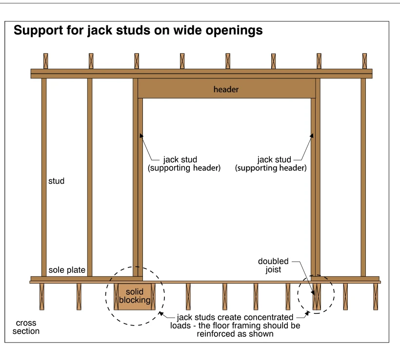 0387
0387Support for jack studs on wide openings
· p. 69
The cross section shows a wood-frame wall with a wide opening spanned by a header supported on jack studs at each end. The jack studs stand on the sole plate and transfer concentrated loads into the floor framing below. Dashed circles highlight solid blocking beneath the left jack stud and a doubled joist beneath the right jack stud. The annotation directs that floor framing be reinforced at these concentrated load locations.
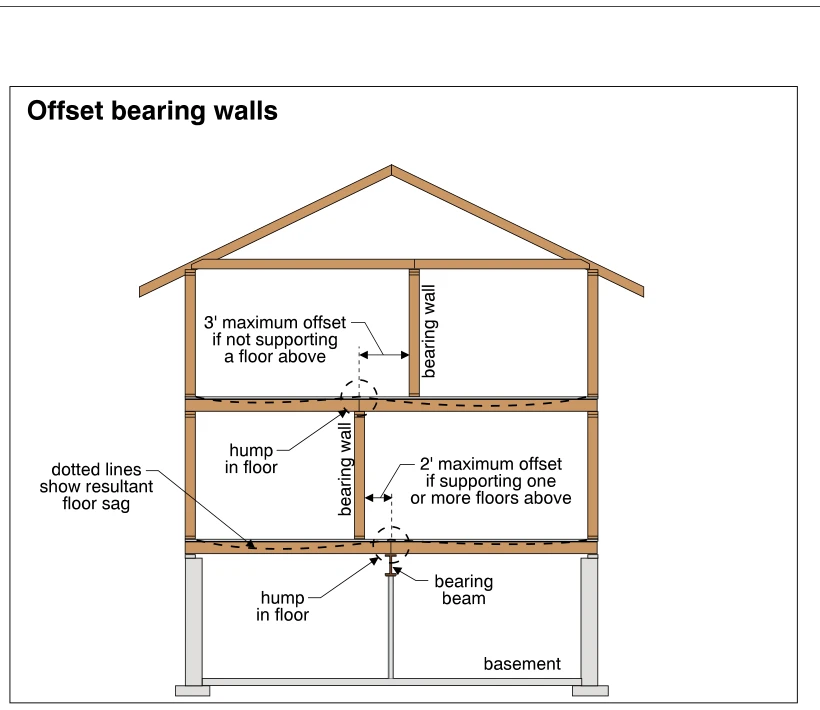 0388
0388Offset bearing walls
· p. 69
The illustration shows a cross-section of a two-story wood-frame house over a basement, with interior bearing walls offset from each other and from the basement bearing beam. Dimension arrows identify a 3-foot maximum offset if not supporting a floor above and a 2-foot maximum offset if supporting one or more floors above. Dashed lines show resultant floor sag between supports, and callouts identify humps in the floors near the underlying bearing wall and beam. The basement beam is supported by a vertical post, while foundation walls support the exterior edges of the house.
 0389
0389Sagging interior header
· p. 69
The illustration shows an interior doorway in a finished wall with downward deflection across the top of the opening. A large downward arrow emphasizes sagging at the center of the concealed header. Diagonal, irregular cracks extend upward and outward from both upper corners of the doorway. The annotations identify this cracking pattern as typically associated with a sagging header hidden behind the finishes.
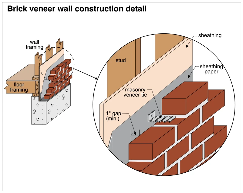 0390
0390Brick veneer wall construction detail
· p. 69
The illustration shows a brick veneer wall outside wood wall framing, with a small cutaway at the floor and foundation and an enlarged wall detail. The enlarged view shows studs behind sheathing and exterior sheathing paper. A minimum 1-inch gap separates the sheathing paper from the brick veneer. A bent masonry veneer tie connects the backing wall to a mortar bed joint in the brickwork.
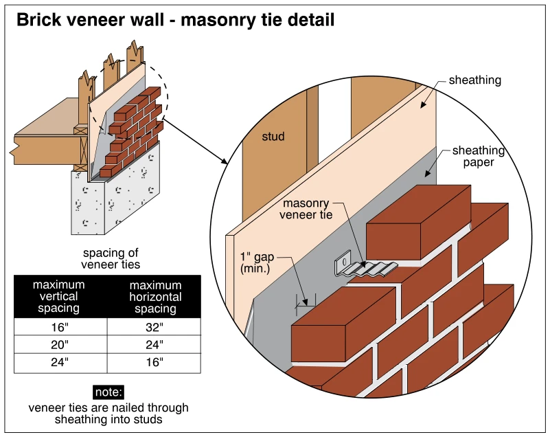 0391
0391Brick veneer wall - masonry tie detail
· p. 69
The illustration shows a brick veneer wall outside a wood-framed wall, with an enlarged detail of a masonry veneer tie. The bent metal tie is nailed through the sheathing into a stud and extends into a mortar joint in the brick veneer. Sheathing paper covers the outer face of the sheathing, and a minimum 1-inch gap separates it from the veneer. A table lists maximum vertical and horizontal tie-spacing combinations of 16 by 32 inches, 20 by 24 inches, and 24 by 16 inches. The smaller overview shows the veneer and framed wall above a concrete foundation.
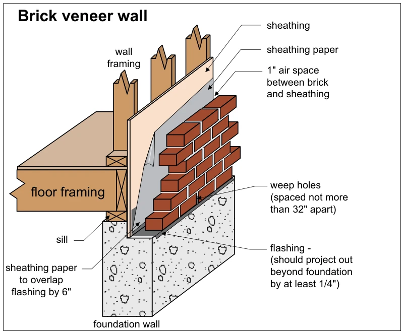 0392
0392Brick veneer wall
· p. 69
The cutaway depicts brick veneer outside a wood-framed wall supported on a concrete foundation wall. Sheathing and sheathing paper separate the wall framing from a labeled 1-inch air space behind the brick. Flashing at the base of the veneer directs drainage toward weep holes spaced not more than 32 inches apart. The annotations specify that sheathing paper overlap the flashing by 6 inches and that flashing project at least 1/4 inch beyond the foundation. Floor framing and a sill are shown on the interior side of the assembly.
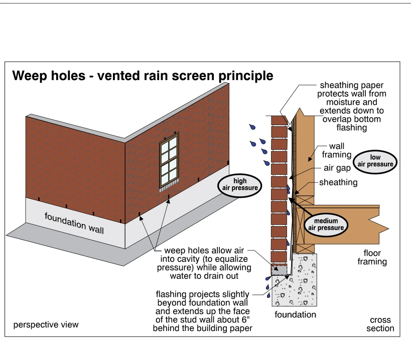 0393
0393Weep holes - vented rain screen principle
· p. 70
The illustration shows a perspective view of a brick veneer wall and a cross section through its base at the foundation and floor framing. Weep holes at the bottom of the veneer admit air to the cavity to equalize pressure while allowing water to drain out. The section identifies high exterior air pressure, medium cavity pressure, and low interior pressure. An air gap separates the brick veneer from the sheathed wood framing, and sheathing paper overlaps the bottom flashing. The flashing turns up approximately 6 inches behind the building paper and projects slightly beyond the foundation wall to discharge water.
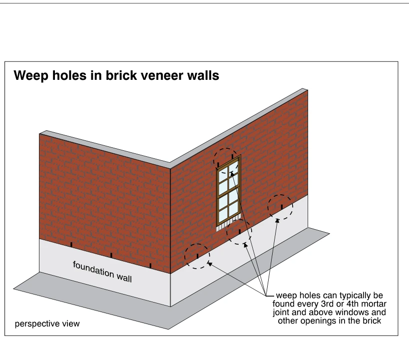 0394
0394Weep holes in brick veneer walls
· p. 70
A perspective view shows two brick veneer walls meeting at an exterior corner above a foundation wall. Small open vertical mortar joints at the base of the veneer represent weep holes. A window is shown in one wall, with additional weep holes above the opening. Dashed circles and arrows highlight weep locations, and the annotation states that they can typically be found every third or fourth mortar joint and above windows and other brick openings.
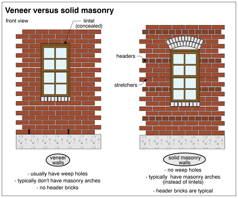 0395
0395Veneer versus solid masonry
· p. 70
Two front elevations compare a brick veneer wall with a solid masonry wall, each containing a window above a concrete base. The veneer wall has stretcher courses, a concealed lintel over the window, and weep openings near the bottom of the brickwork. The solid masonry wall includes header and stretcher bricks and a masonry arch above the window. Annotations identify typical distinguishing features: veneer walls usually have weep holes and no header bricks, while solid masonry walls typically have headers and masonry arches rather than lintels.
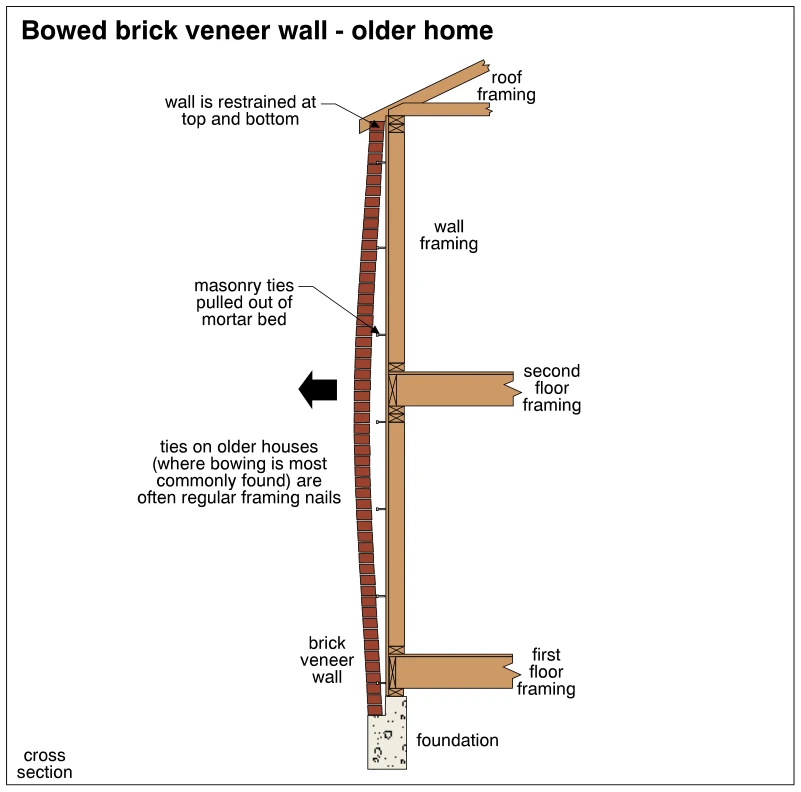 0396
0396Bowed brick veneer wall - older home
· p. 70
The cross section shows a two-story brick veneer wall supported on a foundation alongside wood wall, floor, and roof framing. The veneer is restrained at the top and bottom but bows outward between these points, away from the wall framing. Masonry ties are shown pulled out of the mortar bed, leaving the veneer inadequately connected to the framing. An annotation notes that ties in older houses are often regular framing nails, and a large arrow indicates the outward direction of bowing.
Walls ·Arches and Lintelsp. 71
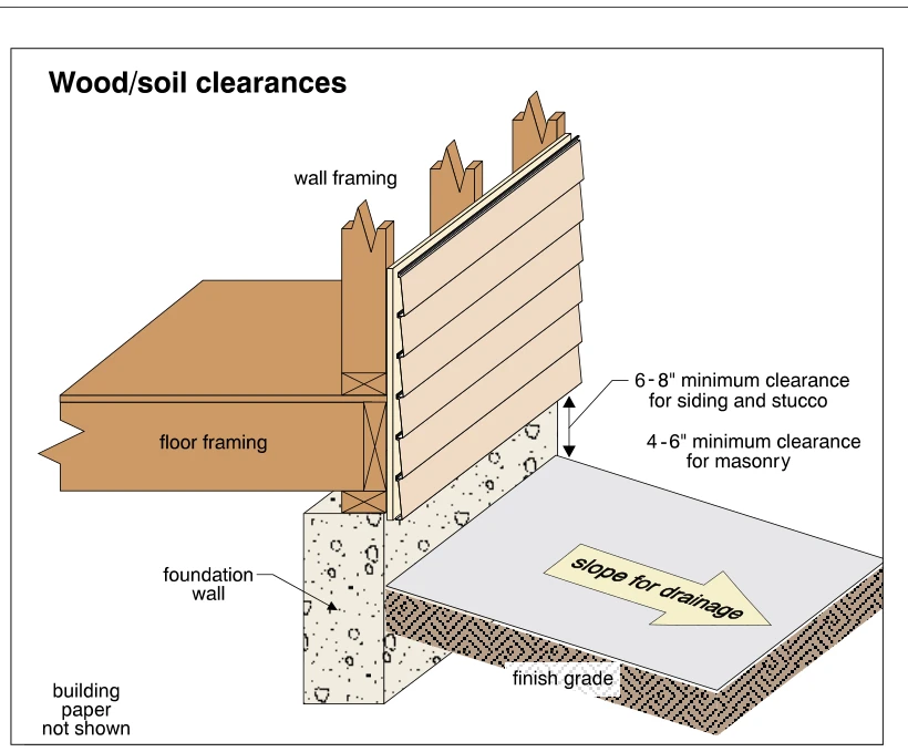 0397
0397Wood/soil clearances
· p. 71
The cutaway shows a wood-framed exterior wall with horizontal lap siding above a concrete foundation wall, with floor framing supported at the foundation. A vertical dimension indicates the separation between the bottom of the exterior cladding and finish grade. Annotations specify 6–8 inches minimum clearance for siding and stucco and 4–6 inches for masonry. The adjacent ground slopes away from the foundation for drainage. Building paper is explicitly noted as not shown.
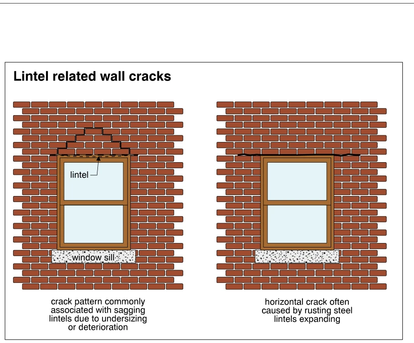 0398
0398Lintel related wall cracks
· p. 71
Two brick veneer wall elevations illustrate lintel-related cracking above window openings. The left elevation shows stepped cracking through mortar joints above the window, associated with a sagging lintel due to undersizing or deterioration. A dashed outline identifies the lintel immediately above the window frame. The right elevation shows a horizontal crack extending beyond both sides of the window head, identified as often caused by expansion of rusting steel lintels. Both windows have projecting sills below their frames.
 0399
0399Steel lintel in brick veneer wall
· p. 71
The cutaway illustration shows a window opening in a brick veneer wall. A steel angle lintel is exposed at the head of the opening, with its horizontal leg supporting the brickwork above. An annotation specifies that the lintel should bear 6 inches on the masonry beside the opening. A row of sloped masonry units forms the sill at the bottom of the opening. The drawing illustrates proper lintel bearing rather than a failure condition.
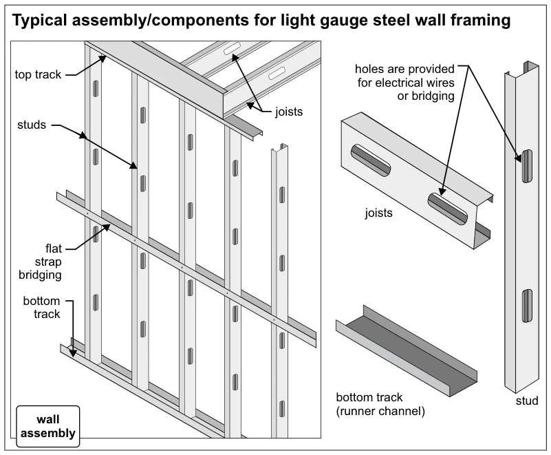 0399.3
Typical assembly/components for light gauge steel wall framing
· p. 71
The illustration shows a light-gauge steel wall assembly with vertical studs seated in a bottom track and capped by a top track, with joists above. Horizontal flat strap bridging crosses the stud faces. Separate details show the channel-shaped profiles of a joist, a stud, and a bottom track or runner channel. Elongated holes in the stud and joist webs are identified as provisions for electrical wires or bridging. No defects or improper practices are indicated.
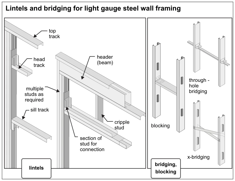 0399.6
Lintels and bridging for light gauge steel wall framing
· p. 71
The illustration shows lintel framing and lateral restraint details for light gauge steel wall studs. The left panel depicts an opening framed with a header beam, head and sill tracks, multiple supporting studs, and a cripple stud beneath the sill. A short section of stud is identified as a connection piece. The right panel shows three arrangements between adjacent studs: solid blocking, through-hole bridging, and crossed diagonal x-bridging. No defects or failed connections are indicated.
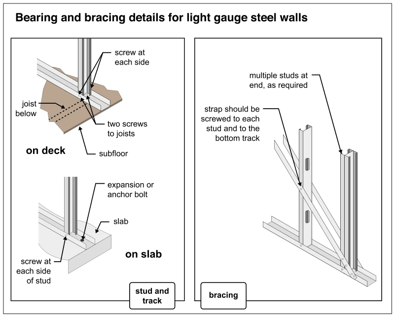 0399.9
Bearing and bracing details for light gauge steel walls
· p. 71
The illustration shows anchorage and diagonal bracing details for light gauge steel stud walls. At a framed deck, the stud is screwed to the bottom track at each side, and the track is secured through the subfloor to the joist below with two screws. At a slab, the stud is similarly screwed to the track, while an expansion or anchor bolt secures the track to the slab. The bracing detail shows a diagonal strap screwed to each stud and to the bottom track, with multiple studs at the wall end as required.
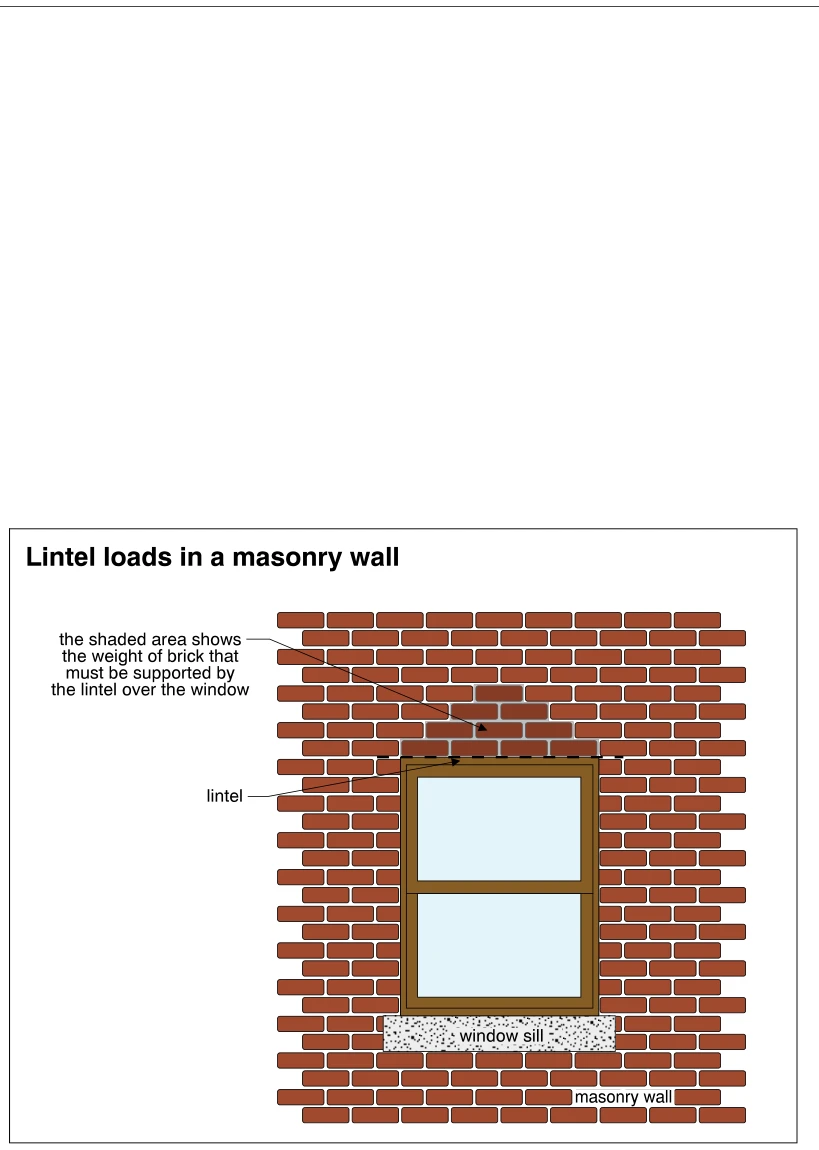 0400
0400Lintel loads in a masonry wall
· p. 72
The illustration shows a window opening in a running-bond brick masonry wall. A horizontal lintel spans the top of the opening and extends onto the masonry on either side. A shaded, roughly triangular area of brick above the window identifies the masonry weight that must be supported by the lintel. The window has two glazed sections and a projecting sill beneath it. No distress or improper installation is depicted.
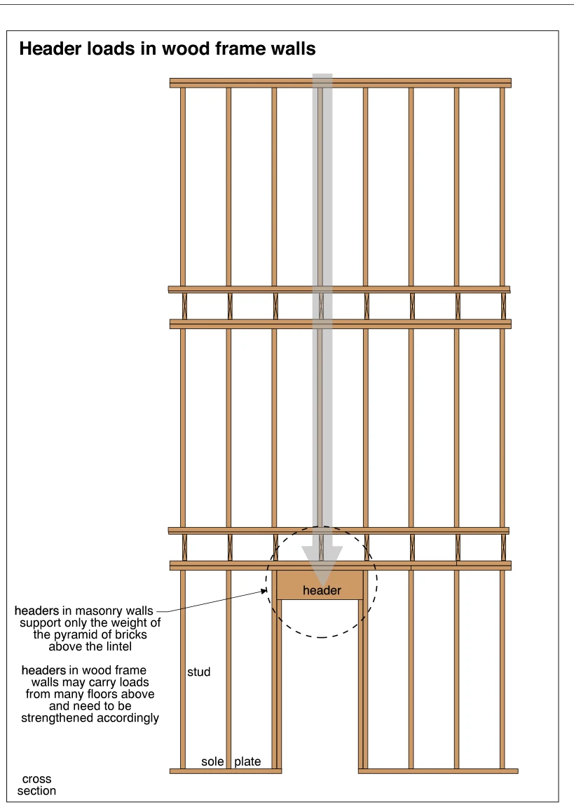 0401
0401Header loads in wood frame walls
· p. 72
The illustration shows a cross section of a multistory wood-frame wall with a framed opening in the lowest story. A header spans the opening and bears on studs at its sides, with wall studs, plates, and floor framing shown above. A large downward arrow traces loading from the upper stories onto the header, which is highlighted by a dashed circle. The annotations explain that wood-frame headers may carry loads from many floors above and must be strengthened accordingly, contrasting this with the stated pyramid of masonry loading above a lintel. No specific damage or undersized member is depicted.
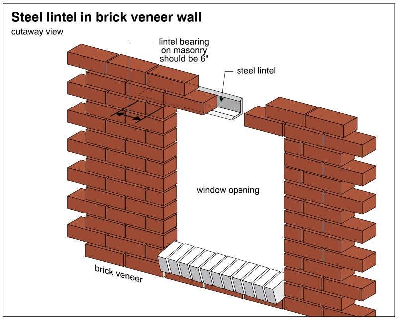 0402
0402Steel lintel in brick veneer wall
· p. 72
A cutaway view shows a window opening in a brick veneer wall with a steel angle lintel at its head. The lintel's horizontal leg supports the brickwork above the opening, while its vertical leg rises behind the veneer. The cutaway exposes part of the lintel and indicates that its bearing on the masonry should be 6 inches. Masonry jambs flank the opening, and a row of sloping masonry units forms the sill.
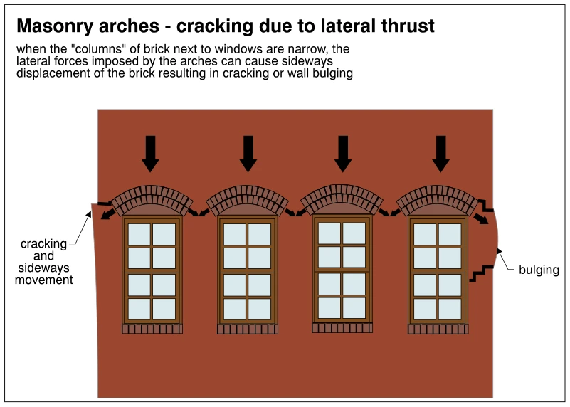 0403
0403Masonry arches - cracking due to lateral thrust
· p. 72
The illustration shows a masonry wall with four adjacent windows topped by segmental brick arches. Large downward arrows indicate vertical loading, while diagonal arrows at the arch ends indicate outward lateral thrust into the narrow masonry piers beside the windows. The left edge of the wall shows cracking and sideways movement near the end of an arch. The right edge shows outward bulging and stepped cracks, illustrating distress caused by lateral thrust where the supporting masonry is narrow.
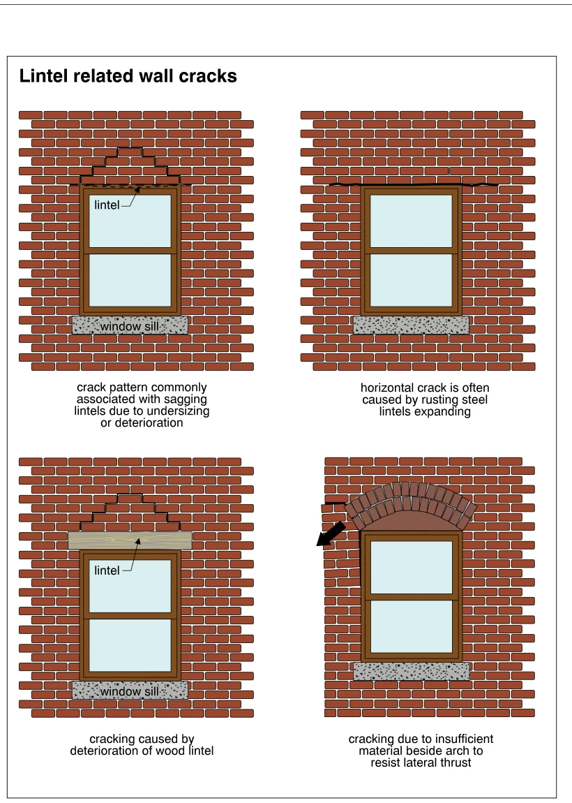 0404
0404Lintel related wall cracks
· p. 73
Four brick-wall elevations illustrate cracking associated with lintels and an arch over window openings. The upper-left example shows stepped mortar-joint cracking above a sagging lintel, attributed to undersizing or deterioration. The upper-right example shows horizontal cracking extending beside the window head, associated with expansion of rusting steel lintels. The lower-left example shows cracking above a deteriorated wood lintel. The lower-right example shows a brick arch with cracking and outward displacement of the narrow wall section beside it, illustrating insufficient masonry to resist lateral thrust.
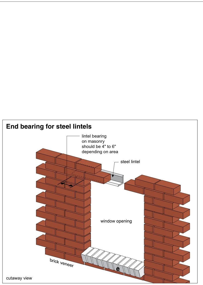 0405
0405End bearing for steel lintels
· p. 73
The cutaway illustration shows a window opening in brick veneer with an angle-shaped steel lintel supporting the masonry above. Part of the masonry is removed to expose the lintel's vertical leg and horizontal supporting flange. Arrows at the left jamb indicate the lintel's end bearing on the masonry beside the opening. The annotation specifies that lintel bearing on masonry should be 4 to 6 inches, depending on area. A course of sloped masonry sill units is shown along the bottom of the opening.
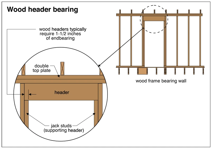 0406
0406Wood header bearing
· p. 73
The illustration shows an opening in a wood-frame bearing wall with an enlarged detail of the header and its end supports. The wood header spans the opening beneath a double top plate and bears on jack studs at both ends. Full-height studs flank the header and jack studs. Dimension arrows identify the end-bearing length, with a note stating that wood headers typically require 1-1/2 inches of end bearing.
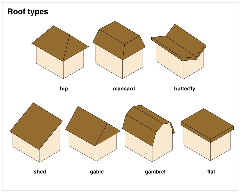 0407
0407Roof types
· p. 73
The illustration shows seven simplified perspective views of residential roof forms on rectangular building masses. The hip roof slopes toward all sides, while the mansard roof has steep lower slopes and shallower upper slopes. The butterfly roof has two planes sloping inward toward a central valley, and the shed roof consists of a single sloping plane. The gable roof has two opposing slopes meeting at a ridge, while the gambrel roof has two slope angles on each side. The flat roof is depicted as a level plane; no roof materials, framing details, or defects are identified.
Roof Framing ·Rafters, Roof Joists and Ceiling Joistsp. 74
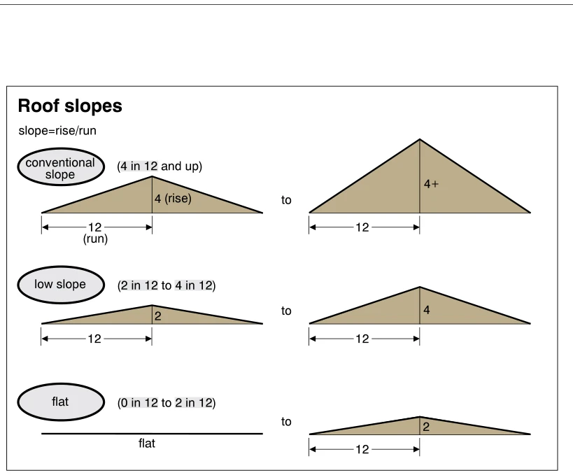 0408
0408Roof slopes
· p. 74
The illustration defines roof slope as rise divided by run and shows schematic roof profiles grouped into three slope categories. Conventional slopes are labeled 4 in 12 and up, low slopes are labeled 2 in 12 to 4 in 12, and flat roofs are labeled 0 in 12 to 2 in 12. Vertical rise lines and horizontal dimension arrows show the rise relative to a run of 12. The flat category includes both a horizontal profile and a shallow pitched profile; no construction details or defects are depicted.
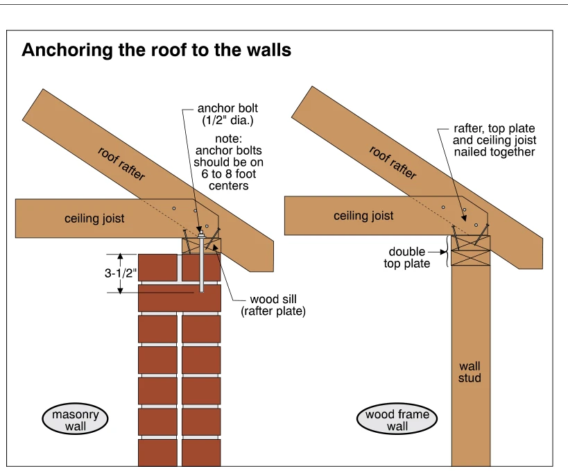 0409
0409Anchoring the roof to the walls
· p. 74
Two sectional details illustrate roof-to-wall anchoring at masonry and wood-frame walls. In the masonry detail, a roof rafter and ceiling joist meet above a wood sill (rafter plate), which is secured to the masonry with an anchor bolt. The bolt is labeled as 1/2 inch in diameter, with spacing of 6 to 8 feet on center, and a 3-1/2-inch vertical dimension is shown beside the upper masonry. In the wood-frame detail, the rafter and ceiling joist meet over a double top plate supported by a wall stud. An annotation specifies that the rafter, top plate, and ceiling joist are nailed together.
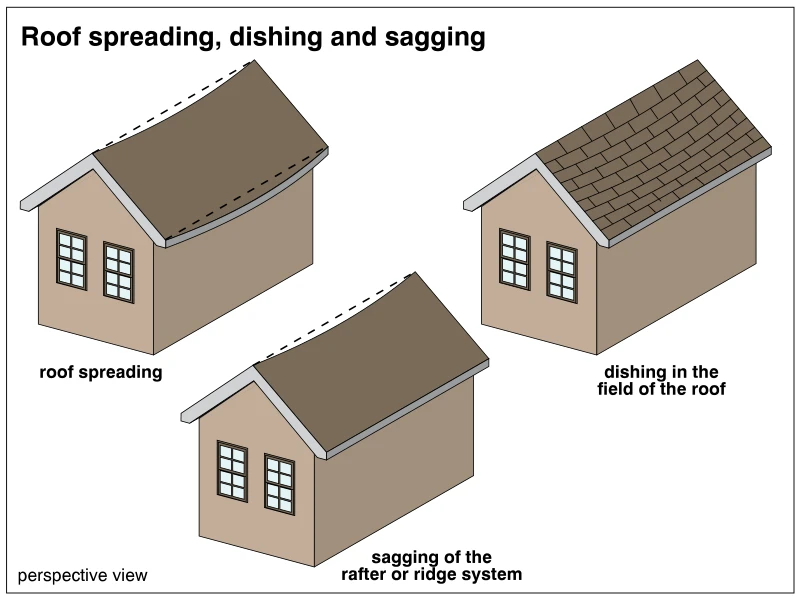 0410
0410Roof spreading, dishing and sagging
· p. 74
Three perspective views of gable-roofed houses illustrate different roof deformation patterns. The roof-spreading example shows bowed roof edges, with dashed reference lines indicating straight alignment. The dishing example uses curved shingle courses to show a depression within the field of the roof. The sagging example shows a depressed ridge profile relative to a dashed straight reference line and identifies sagging of the rafter or ridge system. The underlying framing is not exposed.
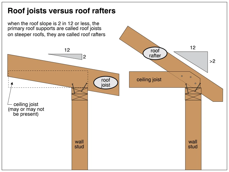 0411
0411Roof joists versus roof rafters
· p. 74
The illustration compares wood roof framing at two slopes, with each roof member bearing on wall top plates above a stud. On the left, a low-slope roof member is identified as a roof joist, and a dashed outline indicates a ceiling joist that may or may not be present. On the right, a steeper roof rafter has a notched bearing at the wall and extends beyond it, with a horizontal ceiling joist attached alongside. Slope diagrams and explanatory text distinguish roof joists at slopes of 2 in 12 or less from roof rafters at slopes greater than 2 in 12. No framing defect is identified.
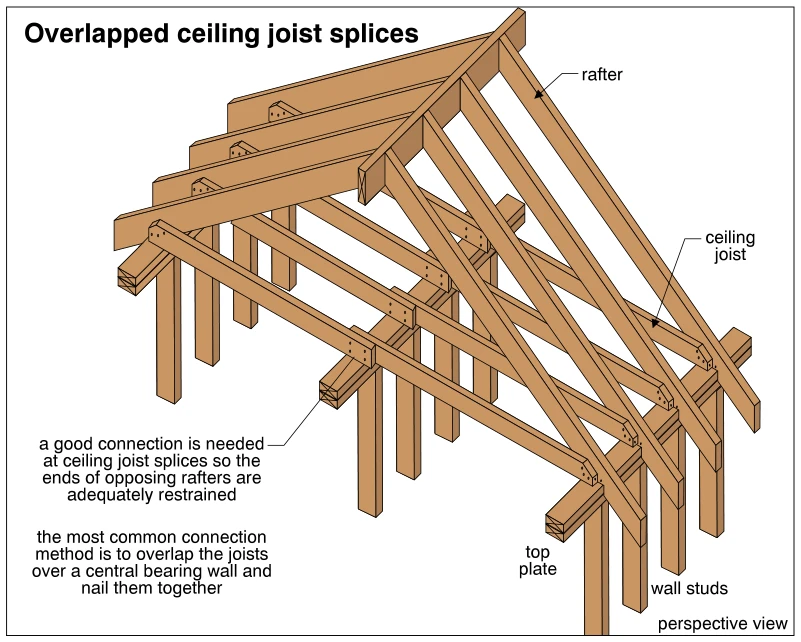 0412
0412Overlapped ceiling joist splices
· p. 74
The perspective drawing shows wood roof rafters and ceiling joists supported by framed walls. Opposing ceiling joists overlap over a central bearing wall, with nails shown connecting the overlapping members. The joists also connect to the rafters at the outer walls, above the wall top plates. The annotation explains that a good splice connection is needed to restrain the ends of opposing rafters and identifies overlapping and nailing the joists over a central bearing wall as the most common method.
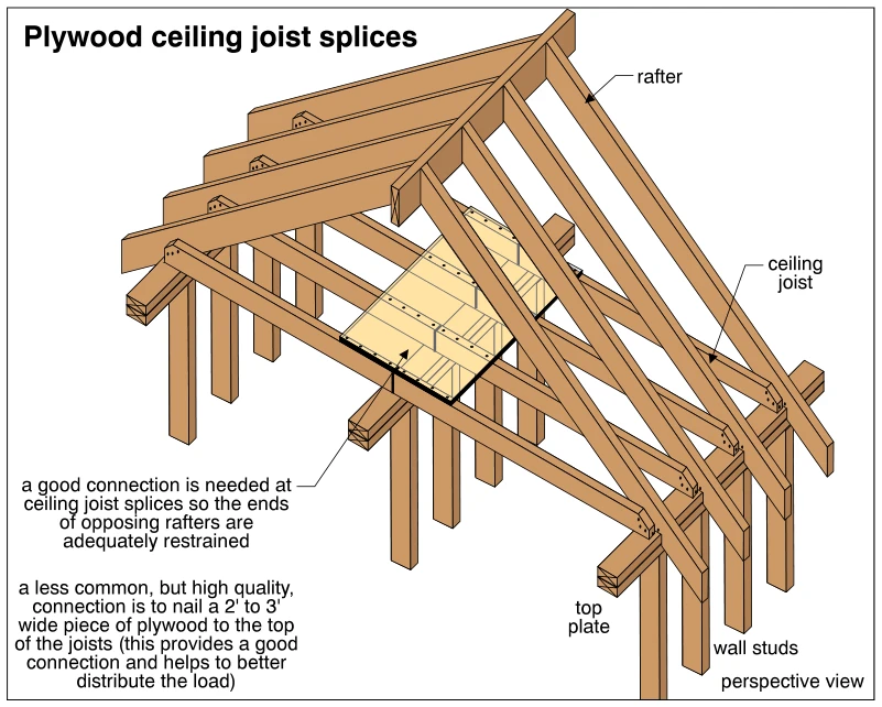 0413
0413Plywood ceiling joist splices
· p. 74
The perspective drawing shows wood roof rafters, ceiling joists, and supporting stud walls with top plates. A plywood panel is nailed across the tops of several ceiling joists at their splice locations. The annotation identifies a 2- to 3-foot-wide plywood piece as a high-quality connection that also helps distribute the load. Secure ceiling joist splices allow the joists to adequately restrain the ends of opposing rafters.
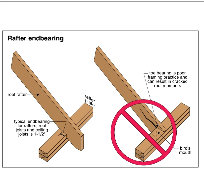 0414
0414Rafter endbearing
· p. 75
The illustration compares two wood rafters bearing on wall plates. The left detail shows a rafter with a horizontal bearing seat and identifies typical end bearing for rafters, roof joists, and ceiling joists as 1-1/2 inches. The right detail shows improper toe bearing at a bird's-mouth notch, marked with a red prohibition symbol. A crack is drawn extending up the rafter from the notch, illustrating the potential damage from this bearing arrangement.
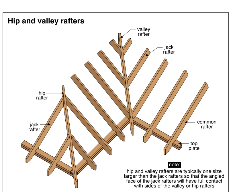 0415
0415Hip and valley rafters
· p. 75
The illustration shows wood roof framing with hip, valley, common, and jack rafters above wall top plates. Jack rafters terminate against the sides of diagonal hip and valley rafters, while common rafters extend along the roof slope. The hip rafter follows an outside roof intersection, and the valley rafter follows an inside roof intersection. A note explains that hip and valley rafters are typically one size larger than jack rafters to provide full contact for the angled ends of the jack rafters. No defects are depicted.
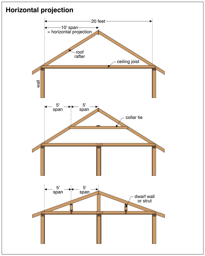 0416
0416Horizontal projection
· p. 75
Three schematic roof-framing cross sections illustrate rafter span measured by horizontal projection rather than along the sloping member. The upper diagram shows a 20-foot-wide gable roof with a 10-foot horizontal rafter span from the exterior wall to the ridge, and a ceiling joist connecting the exterior walls. The middle diagram includes a collar tie and an interior wall beneath the ceiling framing, with the horizontal projection divided into two 5-foot spans. The lower diagram shows a shallower roof with intermediate supports labeled “dwarf wall or strut,” a vertical support beneath the ridge, and an interior wall below. Its horizontal rafter projection is likewise divided into two 5-foot spans.
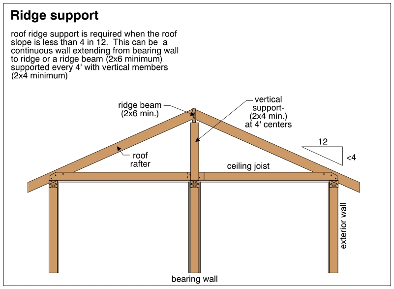 0417
0417Ridge support
· p. 75
The illustration shows a cross-section of a low-slope gable roof with wood rafters meeting at a ridge beam and a horizontal ceiling joist spanning between exterior walls. A vertical member supports the ridge directly above an interior bearing wall, providing a load path down through the center of the assembly. The slope diagram indicates a roof pitch of less than 4 in 12. The annotations specify a minimum 2x6 ridge beam supported by minimum 2x4 vertical members at 4-foot centers, or alternatively a continuous wall extending from the bearing wall to the ridge.
 0418
0418Ridge boards
· p. 76
The perspective drawing shows wood roof framing supported on stud walls and top plates. Opposing sloping rafters meet at a vertical ridge board along the roof peak, with a dashed circle highlighting the ridge connection. Horizontal ceiling joists span between the walls and connect to the rafters near their lower ends. The annotations state that ridge boards are used on roofs with slopes of 4 in 12 or more and are typically nominal 1-inch boards one size larger than the roof rafters.
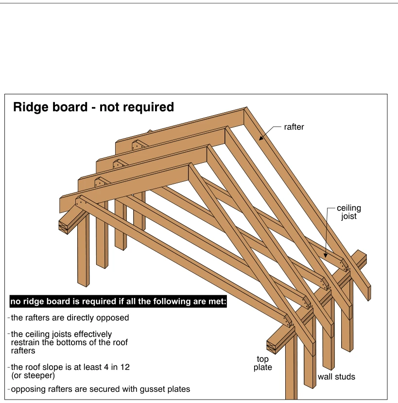 0419
0419Ridge board - not required
· p. 76
The illustration shows wood roof framing with opposing rafters meeting at the ridge without a ridge board. Ceiling joists span between the walls and connect to the lower ends of the rafters, restraining them from spreading. The rafters bear on wall top plates supported by studs, and gusset plates secure the opposing rafters at the ridge. The annotations state that omitting the ridge board requires directly opposed rafters, effective restraint by ceiling joists, a roof slope of at least 4 in 12, and gusset plates securing opposing rafters.
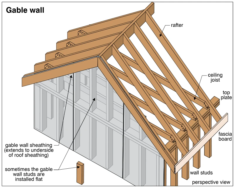 0420
0420Gable wall
· p. 76
The perspective drawing shows a wood-framed gable roof with exposed rafters, ceiling joists, and supporting wall framing. The triangular gable-end wall is framed with vertical studs of varying lengths beneath the roof slopes. Gable wall sheathing extends to the underside of the roof sheathing, as noted in the callout. Ceiling joists connect to the rafters near the wall top plate, and a fascia board runs along the eave. A separate stud detail indicates that gable wall studs are sometimes installed flat.
 0421
0421Gable overhang less than 16 inches
· p. 76
The illustration shows wood roof and wall framing at a gable end with an overhang less than 16 inches. A rake rafter forms the projecting roof edge, with horizontal braces connecting it to the adjacent framing. A nailing strip is specified as 1 inch wide and the same depth as the rafters. Partial roof sheathing covers the sloped framing, and the gable wall sheathing extends to the underside of the roof sheathing. Ceiling joists, wall studs, the top plate, and an eave fascia board are also identified.
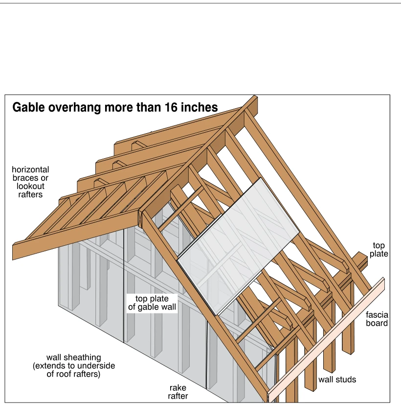 0422
0422Gable overhang more than 16 inches
· p. 77
The illustration shows exposed wood framing at a gable roof with an overhang more than 16 inches wide. Horizontal braces, or lookout rafters, extend from the roof framing across the gable wall to support the outer rake rafter. The gable wall top plate and studs are shown beneath the sloped roof framing, with wall sheathing extending to the underside of the roof rafters. A fascia board runs along the lower eave, and a partial roof sheathing panel covers some of the rafters. The drawing presents the support arrangement without identifying any defects.
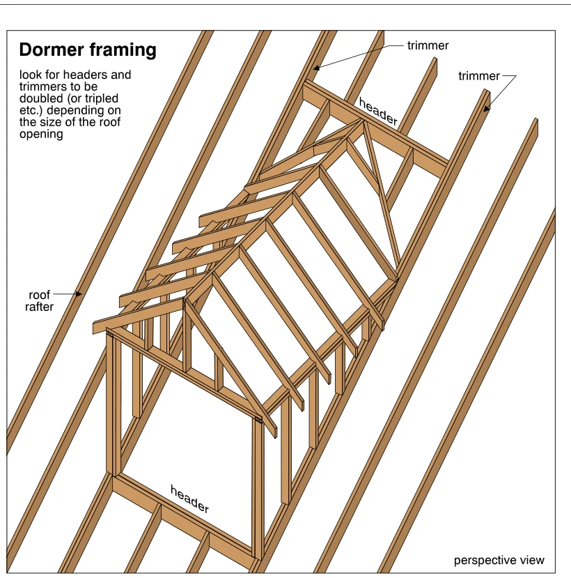 0423
0423Dormer framing
· p. 77
The perspective drawing shows wood framing for a gable dormer projecting from a sloped roof. Headers span between trimmer rafters at the upper and lower ends of the roof opening. The dormer has framed sidewalls, a front wall opening, and paired roof rafters meeting along a central ridge. The annotation directs inspectors to look for doubled or tripled headers and trimmers, depending on the size of the roof opening.
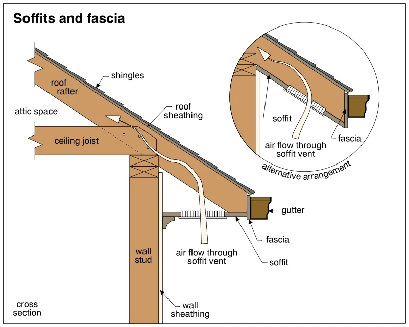 0424
0424Soffits and fascia
· p. 77
The illustration shows a cross section of a roof eave above an exterior framed wall, identifying the roof rafter, ceiling joist, roof sheathing, shingles, and wall framing. A horizontal soffit encloses the underside of the overhang, while a vertical fascia closes the rafter end and supports the adjacent gutter. An arrow traces airflow through a soffit vent and upward into the attic space. A circular inset shows an alternative arrangement with a sloping soffit following the roof pitch, also incorporating a vent. No defects are depicted.
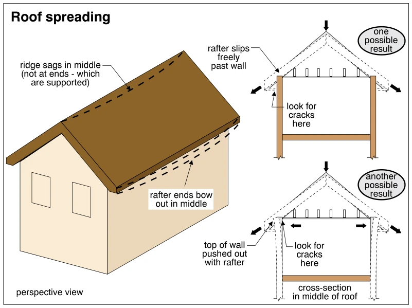 0425
0425Roof spreading
· p. 77
A perspective view of a gable-roofed house shows the ridge sagging in the middle while the supported ends remain higher, and the rafter ends bowing outward along the middle of the eaves. Two cross-sections illustrate possible results of roof spreading, with dashed outlines indicating displaced positions. In the upper section, the rafters slip outward past the supporting walls while the walls remain upright. In the lower section, the spreading rafters push the tops of the walls outward. Callouts identify the roof-to-wall junctions as locations to look for cracks.
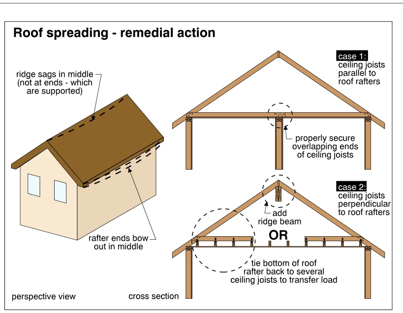 0426
0426Roof spreading - remedial action
· p. 78
A perspective view of a gable-roofed house shows the ridge sagging between supported ends and the rafter ends bowing outward at midspan along the walls. Two cross sections illustrate remedial options based on ceiling-joist orientation. Where ceiling joists run parallel to the rafters, the illustration calls for properly securing their overlapping ends over the central support. Where ceiling joists run perpendicular to the rafters, the alternatives shown are adding a ridge beam or tying the bottom of the roof rafter back to several ceiling joists to transfer load.
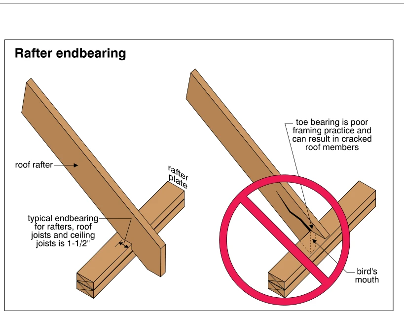 0427
0427Rafter endbearing
· p. 78
The illustration compares two wood-rafter bearing details at a rafter plate. On the left, a notched rafter seats on the plate, with typical endbearing for rafters, roof joists and ceiling joists identified as 1-1/2 inches. On the right, a bird's-mouth detail provides toe bearing rather than the illustrated proper seating. A crack is drawn extending up the improperly supported rafter, and a red prohibition symbol marks this arrangement as poor framing practice.
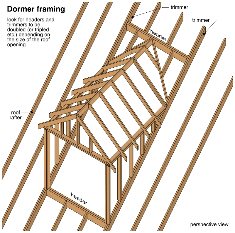 0428
0428Dormer framing
· p. 78
A perspective drawing shows wood framing for a gable dormer projecting from a sloping roof. Headers span between trimmer rafters at the upper and lower ends of the roof opening, with the surrounding roof rafters shown alongside. The dormer has framed sidewalls, a large front opening, and paired rafters forming its gable roof. An inspection note calls for headers and trimmers to be doubled or tripled as appropriate to the size of the roof opening.
 0429
0429Watch for insufficient nails in joist hangers
· p. 78
The perspective drawing shows two wood joists connected to a built-up wood supporting member with metal joist hangers. A red prohibition symbol overlays the left connection to warn against insufficient nailing. The exposed hanger flanges show the fastener locations along the sides of the joists. Annotations state that all nail holes in the hangers should be used and that nail heads must be large enough to prevent pull-through.
Roof Framing ·Collar Ties, Knee Walls and Purlinsp. 79
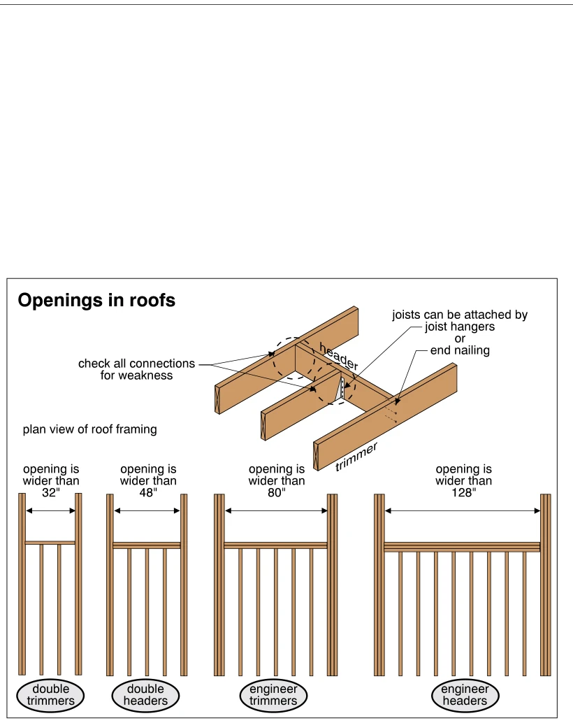 0430
0430Openings in roofs
· p. 79
The illustration depicts wood roof framing around openings, with a perspective connection detail and four plan-view examples. The detail identifies a header and trimmer, shows a joist hanger, and notes that joists can be attached by joist hangers or end nailing. Dashed circles highlight connections to check for weakness. The plan views specify double trimmers for openings wider than 32 inches, double headers for openings wider than 48 inches, engineered trimmers for openings wider than 80 inches, and engineered headers for openings wider than 128 inches.
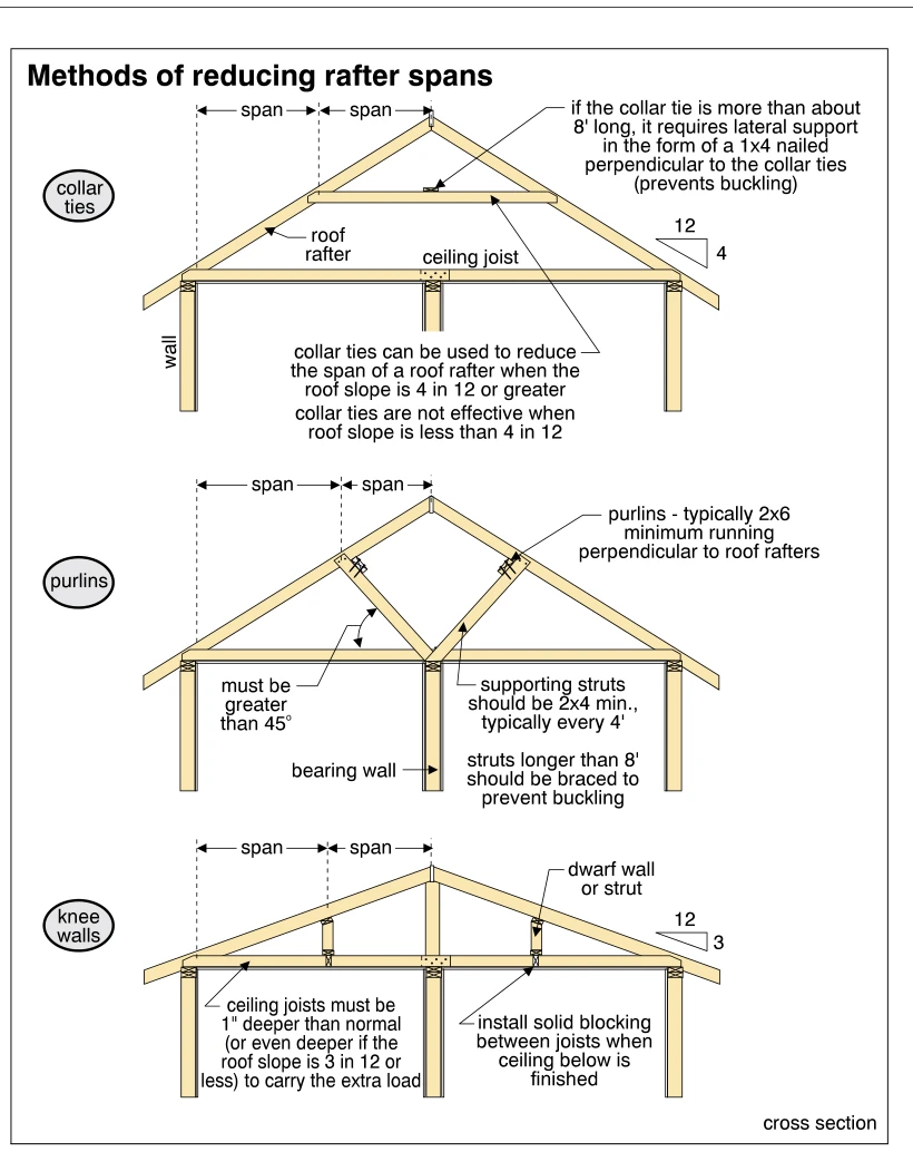 0431
0431Methods of reducing rafter spans
· p. 79
Three roof-framing cross sections illustrate methods of reducing unsupported rafter spans using collar ties, purlins with inclined struts, and knee walls. The upper diagram shows a horizontal collar tie between opposing rafters and notes roof-slope limitations and lateral bracing requirements for long ties. The middle diagram shows purlins beneath the rafters supported by inclined struts that transfer load to a central bearing wall, with annotations for strut angle, size, spacing, and bracing. The lower diagram shows dwarf walls or vertical struts supporting a lower-slope roof above the ceiling joists. Its annotations call for deeper ceiling joists to carry the added load and solid blocking between joists where the ceiling below is finished.
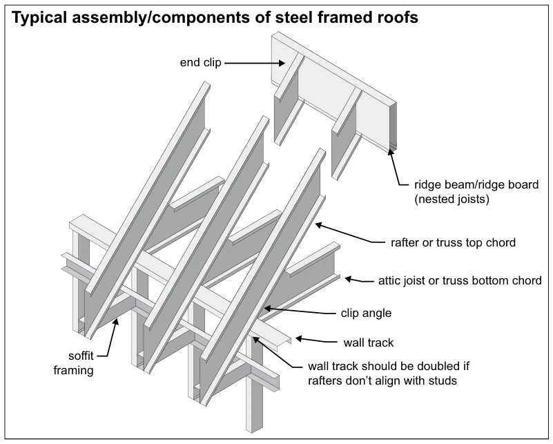 0432.4
Typical assembly/components of steel framed roofs
· p. 79
An exploded perspective illustrates a steel-framed roof assembly supported on steel wall studs and wall track. Sloping rafters or truss top chords extend toward a ridge beam/ridge board formed from nested joists, with an end clip identified at the ridge connection. Horizontal attic joists or truss bottom chords intersect the sloping members, and a clip angle is identified near the wall bearing area. Soffit framing is shown beneath the projecting roof members. An annotation specifies that the wall track should be doubled where rafters do not align with studs.
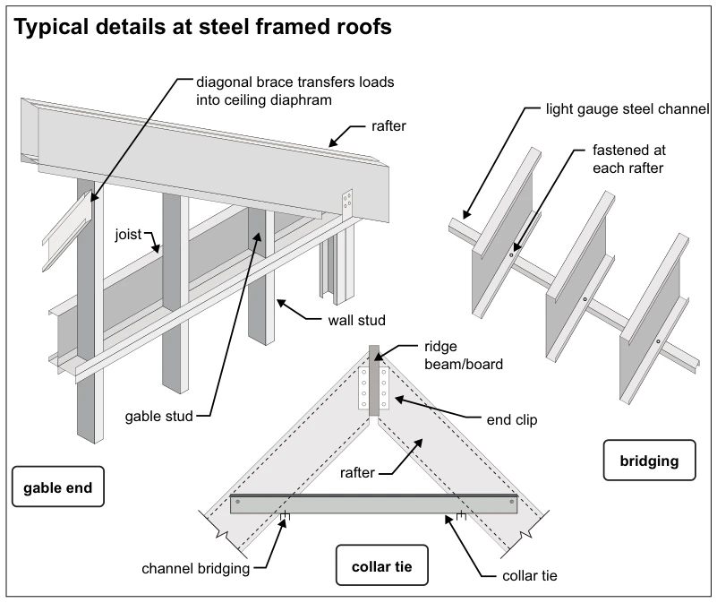 0432.8
Typical details at steel framed roofs
· p. 79
Three details illustrate light-gauge steel roof framing at a gable end, rafter bridging, and a collar tie. The gable-end detail shows rafters, joists, wall studs, and gable studs, with a diagonal brace identified as transferring loads into the ceiling diaphragm. The bridging detail shows a light-gauge steel channel crossing the rafters and fastened at each rafter. The collar-tie detail shows opposing rafters meeting at a ridge beam/board with end clips, a horizontal collar tie spanning between them, and channel bridging below the rafters. No defects are identified.
Roof Framing ·Trussesp. 80
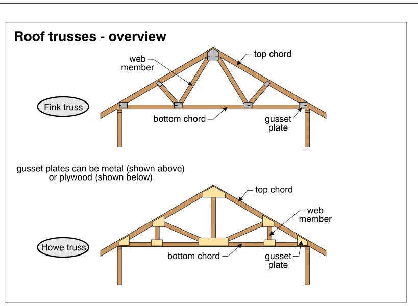 0433
0433Roof trusses - overview
· p. 80
The illustration shows two triangular wood roof-truss configurations: a Fink truss above and a Howe truss below. Each has sloping top chords, a horizontal bottom chord, and internal web members, with supports beneath the ends of the bottom chord and top chords extending beyond them. The Fink truss has a W-shaped web arrangement with metal gusset plates at the joints. The Howe truss has vertical and diagonal web members with plywood gusset plates at the joints. The drawing identifies truss components and connection materials without depicting defects.
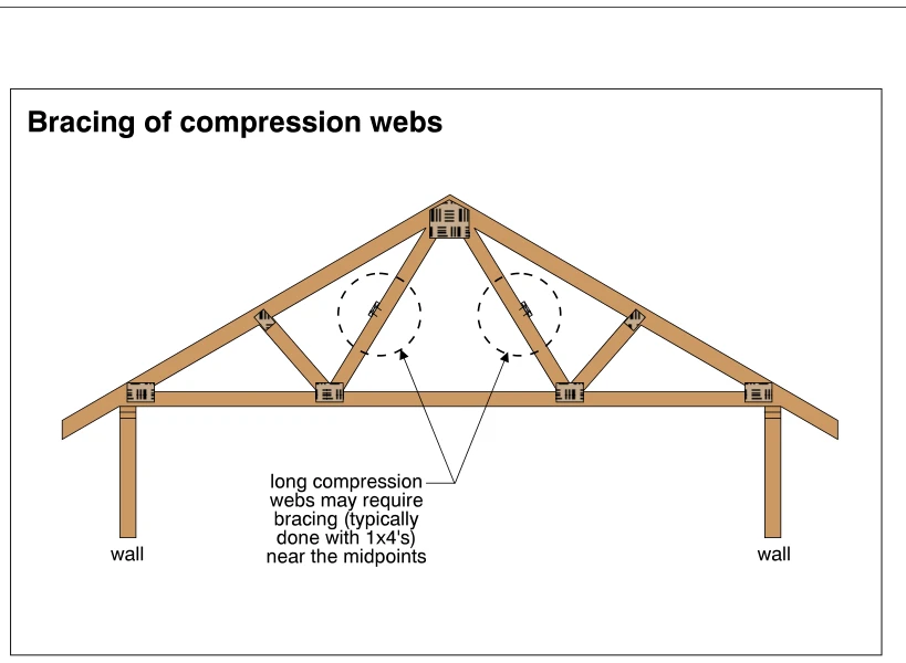 0434
0434Bracing of compression webs
· p. 80
The illustration shows a wood roof truss supported on walls at each end, with sloping top chords, a horizontal bottom chord, and diagonal webs connected by metal connector plates. Two long compression webs extend from the ridge joint to intermediate bottom-chord joints. Dashed circles and arrows highlight bracing locations near the midpoints of these webs. The annotation notes that long compression webs may require bracing, typically using 1x4 lumber.
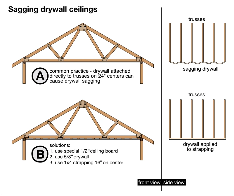 0435
0435Sagging drywall ceilings
· p. 80
The illustration compares two ceiling-support arrangements beneath wood roof trusses in front and side views. Arrangement A shows drywall attached directly to trusses spaced 24 inches on center, with the side view depicting sagging between trusses. Arrangement B shows strapping beneath the truss bottom chords and a flat drywall ceiling applied to the strapping. Listed solutions are special 1/2-inch ceiling board, 5/8-inch drywall, or 1x4 strapping spaced 16 inches on center.
 0436
0436Truss types
· p. 80
The illustration presents fourteen labeled truss configurations in two columns, showing their outer profiles and internal web arrangements. The left column shows seven pitched, triangular trusses with horizontal bottom chords and differing vertical and diagonal webs. The right column includes a scissor truss with raised bottom chords, three single-slope mono trusses, and parallel-chord Pratt and Warren trusses. A gable-end configuration has a horizontal bottom chord and closely spaced vertical members beneath its pitched top chords. These are schematic framing diagrams; connections, dimensions, and defects are not shown.
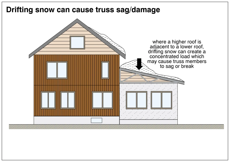 0437
0437Drifting snow can cause truss sag/damage
· p. 80
The illustration shows a tall gable-roofed house adjoining a lower, sloped-roof addition. A cutaway at the lower roof exposes its triangular truss framing. Snow is piled more deeply on the lower roof near the taller building, and a downward arrow indicates the concentrated load. The annotation explains that drifting snow at this roof-height transition may cause truss members to sag or break.
 0438
0438Roof truss uplift
· p. 80
Two cross sections illustrate uplift of a wood roof truss spanning exterior walls above a central interior wall. The upper drawing shows insulation around the bottom chord and arrows indicating expansion of colder, wetter wood and shrinkage of warmer, drier wood. The lower drawing, with insulation omitted for clarity, shows the bottom chord bowing upward at midspan while its ends remain supported on the exterior walls. This movement separates the ceiling from the central wall, forming cracks at the wall/ceiling intersections.
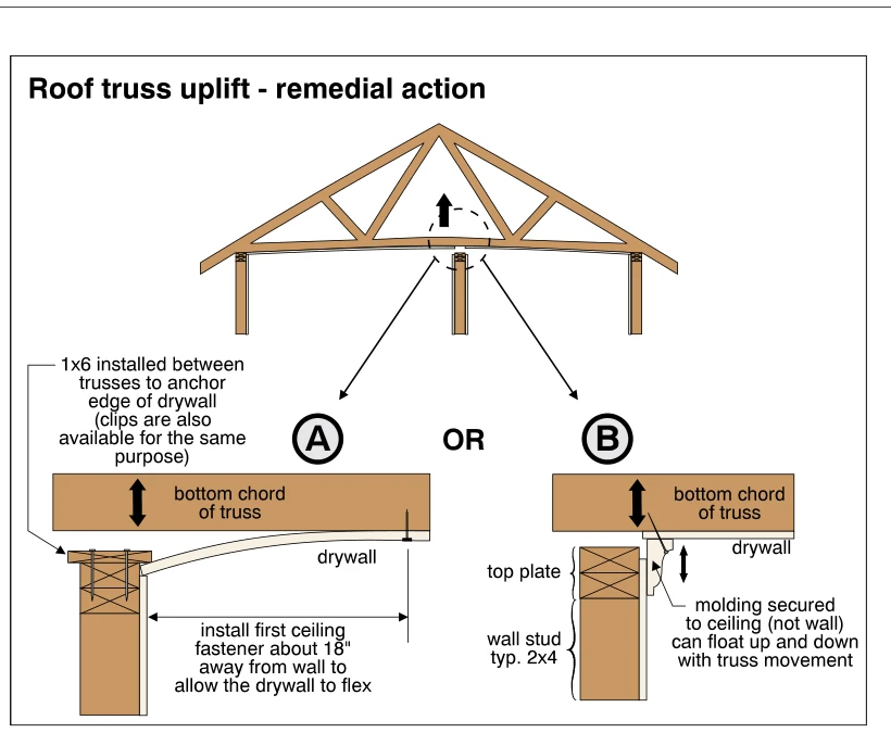 0439
0439Roof truss uplift - remedial action
· p. 81
The illustration shows a wood roof truss lifting above an interior partition and two alternative remedial details at the ceiling-to-wall junction. Detail A anchors the ceiling drywall edge to a 1x6 installed between trusses, with clips noted as an alternative. The first ceiling fastener is placed about 18 inches away from the wall so the drywall can flex as the bottom chord moves. Detail B uses molding secured to the ceiling rather than the wall, allowing the molding to move up and down with the truss. Arrows indicate vertical movement of the truss bottom chord and the floating molding.
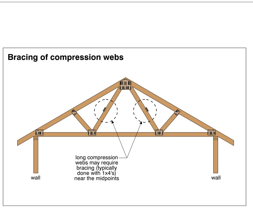 0440
0440Bracing of compression webs
· p. 81
The illustration shows a triangular wood roof truss bearing on walls at both ends of its horizontal bottom chord. Sloping top chords and diagonal web members are joined with metal connector plates. Dashed circles highlight the approximate midpoints of the two long compression webs extending from the lower chord toward the ridge. An annotation states that these webs may require bracing, typically using 1x4 lumber, near their midpoints.
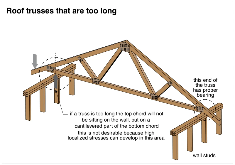 0441
0441Roof trusses that are too long
· p. 81
The illustration shows a wood roof truss spanning two stud-framed walls, with metal connector plates at its chord and web joints. At the left end, the truss heel extends beyond the supporting wall, so the top chord bears on a cantilevered portion of the bottom chord rather than directly over the wall. Arrows and a dashed circle highlight this offset load path, where the annotation warns that high localized stresses can develop. The right end is circled and identified as having proper bearing, providing a comparison with the improperly supported left end.
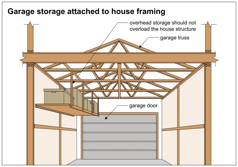 0441.5
Garage storage attached to house framing
· p. 81
The illustration shows a garage interior with exposed wood wall framing and roof trusses above a sectional garage door. An overhead storage platform along the left side holds boxes and is suspended from the framing by vertical wood members. The drawing shows the storage load being carried by the building framing rather than by supports extending to the floor. A caution states that overhead storage should not overload the house structure; no actual structural damage is depicted.
Roof Framing ·Sheathingp. 82
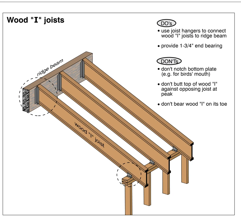 0442
0442Wood "I" joists
· p. 82
Three sloping wood I-joists extend from a ridge beam to the top of a stud wall. Metal joist hangers connect their upper ends to the ridge beam, and their lower ends bear on the wall framing. Dashed circles emphasize the ridge connection and lower bearing detail. Notes specify joist hangers and 1-3/4-inch end bearing, and warn against notching the bottom plate for a birdsmouth, butting opposing joist tops at the peak, or bearing an I-joist on its toe.
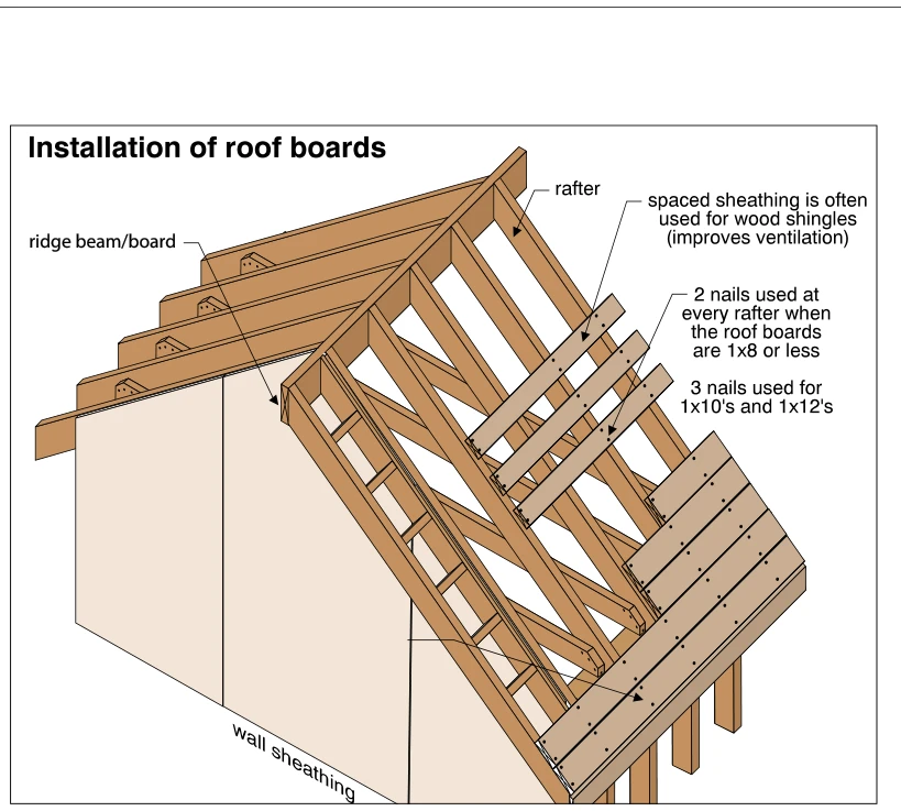 0443
0443Installation of roof boards
· p. 82
The cutaway illustration shows a wood-framed sloping roof with rafters meeting a ridge beam/board and roof sheathing boards running perpendicular to the rafters. Both spaced and closely laid roof boards are shown, with nail locations marked at the rafter intersections. An annotation identifies spaced sheathing as commonly used for wood shingles to improve ventilation. Fastening instructions specify two nails at every rafter for boards 1x8 or less and three nails for 1x10 and 1x12 boards. Wall sheathing and portions of the supporting framing are exposed below the roof.
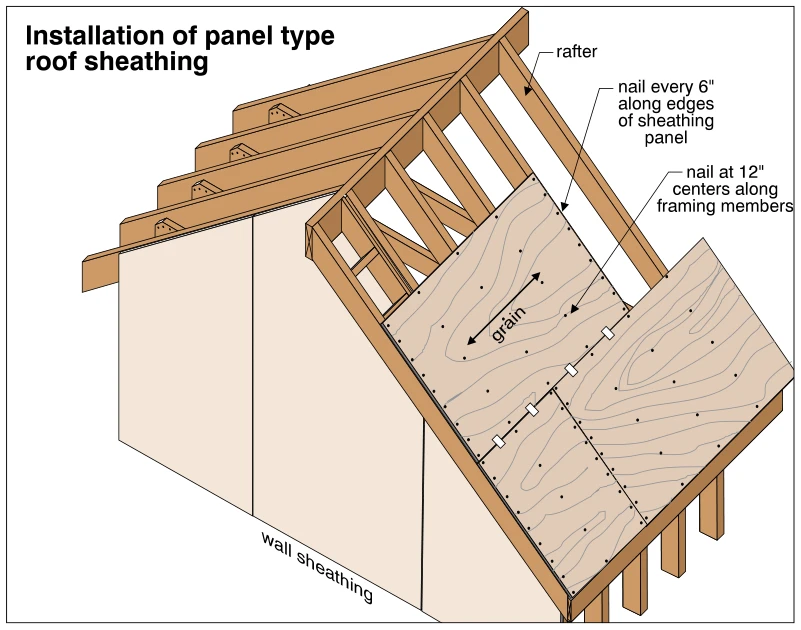 0444
0444Installation of panel type roof sheathing
· p. 82
The illustration shows plywood roof sheathing partially installed over a pitched wood roof frame, with exposed rafters and wall sheathing below. The grain direction is indicated perpendicular to the rafters, and adjacent rows of panels have staggered end joints. Small panel-edge clips are shown along an unsupported joint between rafters. Nail locations are illustrated with annotations specifying 6-inch spacing along panel edges and 12-inch spacing along framing members.
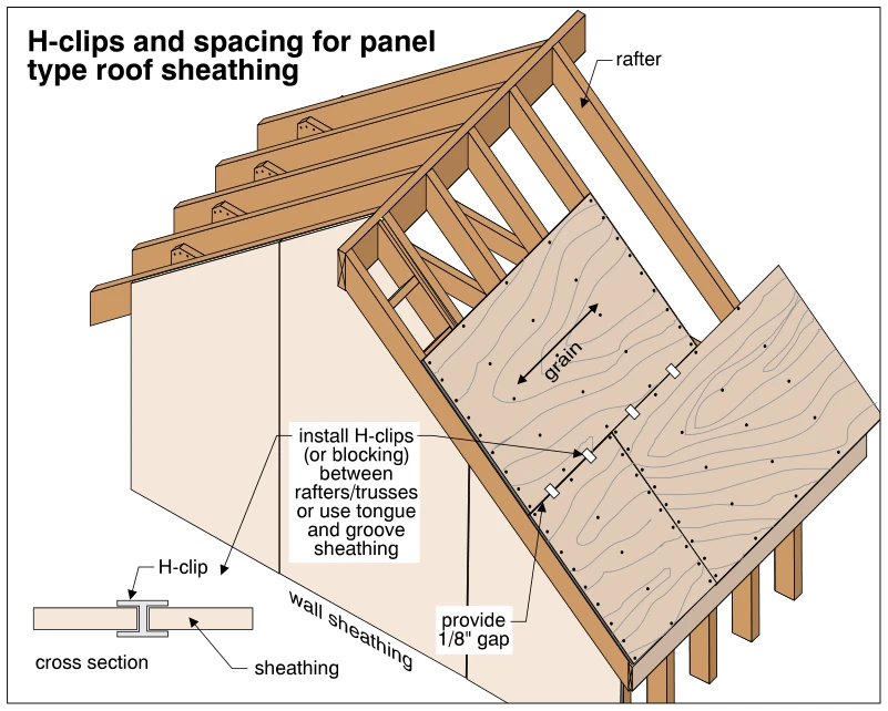 0445
0445H-clips and spacing for panel type roof sheathing
· p. 82
The illustration shows a partially sheathed wood-framed roof with exposed rafters and panel roof sheathing fastened to the framing. A grain arrow indicates the panel grain orientation across the rafters. H-clips are installed along adjoining panel edges between rafters, and a callout specifies a 1/8-inch gap between panels. An inset cross section shows an H-clip engaging the edges of two adjacent sheathing panels. The annotation identifies blocking or tongue-and-groove sheathing as alternatives to H-clips for panel-edge support.
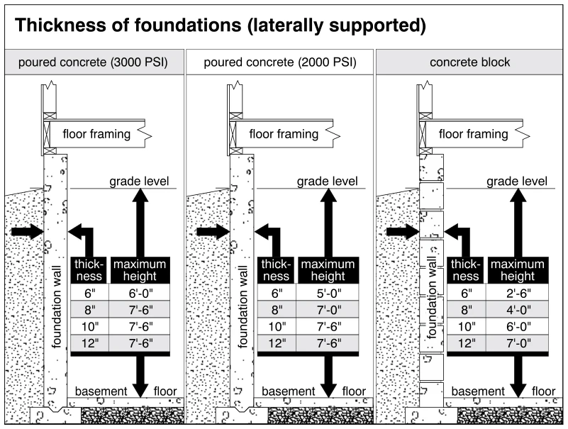 0447
0447Thickness of foundations (laterally supported)
· p. 82
Three foundation-wall sections compare wall thickness and maximum height for laterally supported foundations made of 3000 PSI poured concrete, 2000 PSI poured concrete, and concrete block. Each section shows floor framing at the top, soil against the exterior, and a basement floor and footing at the bottom; vertical arrows measure the indicated height between basement floor and exterior grade. For wall thicknesses of 6, 8, 10, and 12 inches, the 3000 PSI concrete table lists maximum heights of 6 feet, 7 feet 6 inches, 7 feet 6 inches, and 7 feet 6 inches, respectively. For the same thicknesses, the 2000 PSI concrete table lists 5 feet, 7 feet, 7 feet 6 inches, and 7 feet 6 inches, while the concrete-block table lists 2 feet 6 inches, 4 feet, 6 feet, and 7 feet. The illustration presents dimensional comparisons rather than a visible foundation defect.
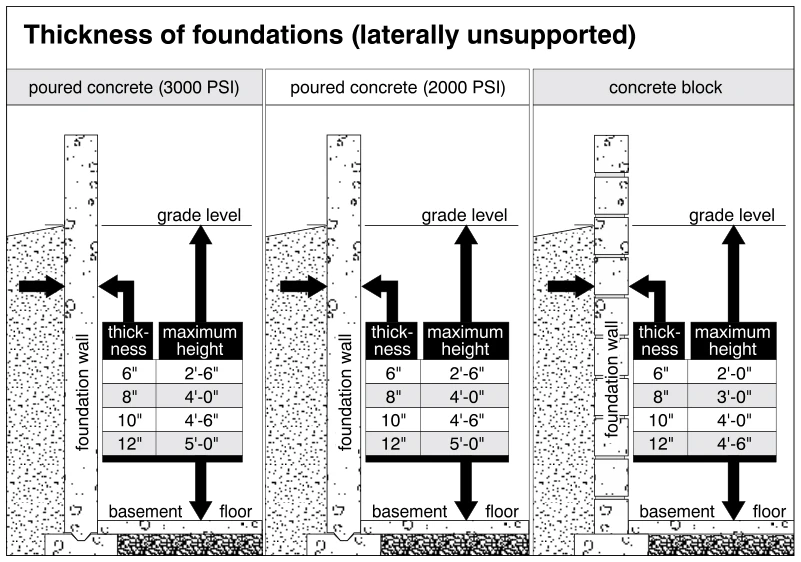 0448
0448Thickness of foundations (laterally unsupported)
· p. 82
Three side-by-side foundation sections compare wall thickness and maximum height for laterally unsupported poured-concrete and concrete-block foundations. Each section shows exterior soil up to grade level, a foundation wall on a footing, and an interior basement floor; arrows identify wall thickness and the vertical distance from basement floor to grade. Both the 3000 PSI and 2000 PSI poured-concrete tables list maximum heights of 2 feet 6 inches, 4 feet, 4 feet 6 inches, and 5 feet for wall thicknesses of 6, 8, 10, and 12 inches, respectively. The concrete-block table lists maximum heights of 2 feet, 3 feet, 4 feet, and 4 feet 6 inches for those same thicknesses. No damage or specific defective installation is illustrated.