
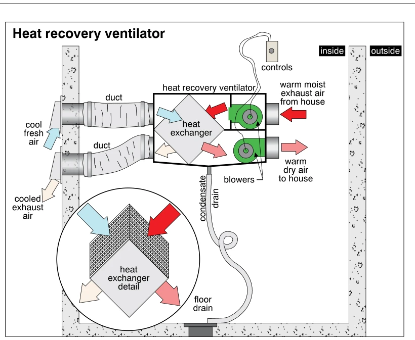
Related illustrations
 1354
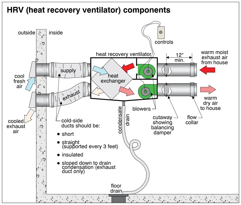
1354HRV (heat recovery ventilator) components
· p. 243
The schematic shows a heat recovery ventilator connected through an exterior wall to fresh-air intake and exhaust ducts, with two additional ducts serving the house. Arrows show cool fresh air passing through the heat ex
 1401
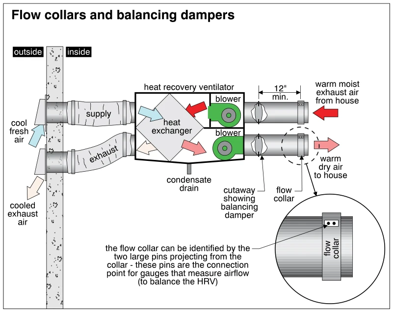
1401Flow collars and balancing dampers
· p. 255
The illustration shows a heat recovery ventilator (HRV) connected to outdoor intake and exhaust ducts and two house-side air ducts. Arrows trace cool fresh air and warm moist house exhaust through a heat exchanger, with
 1353
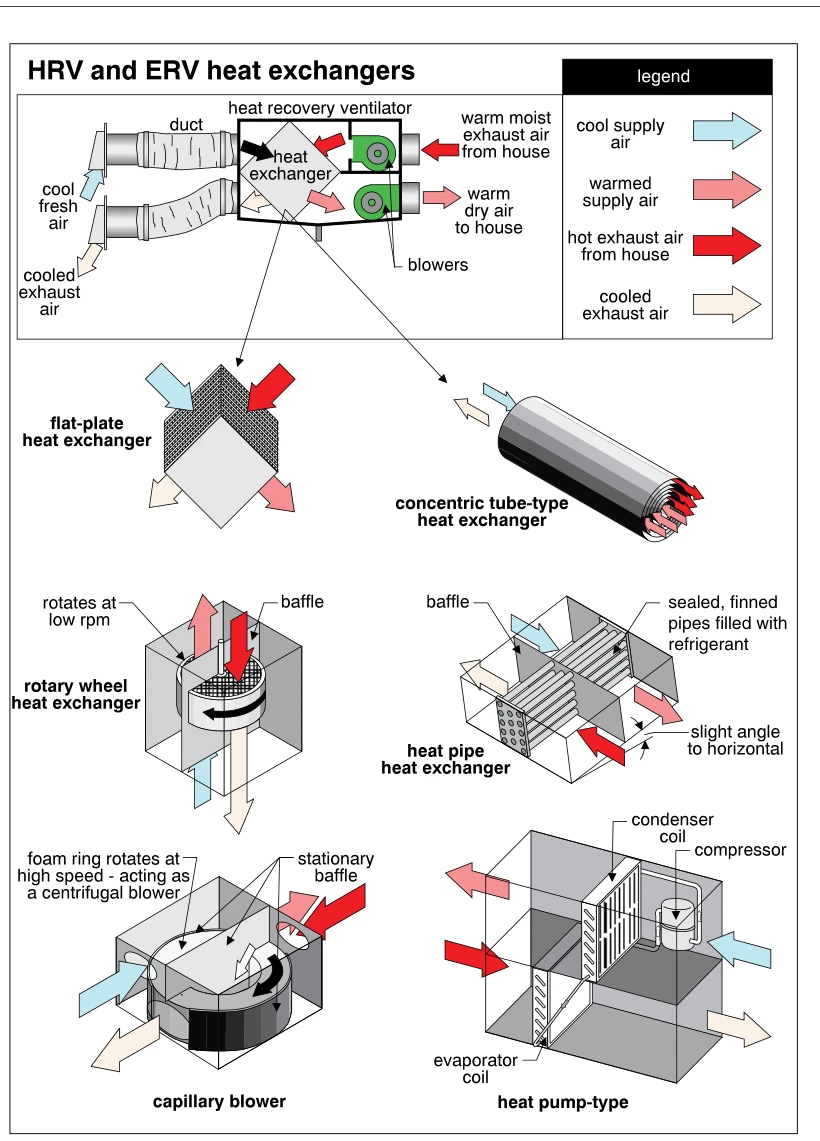
1353HRV and ERV heat exchangers
· p. 243
The illustration shows a ducted heat recovery ventilator with two blowers and a heat exchanger transferring heat from warm house exhaust air to incoming cool fresh air. Color-coded arrows distinguish cool supply air, war
 1404
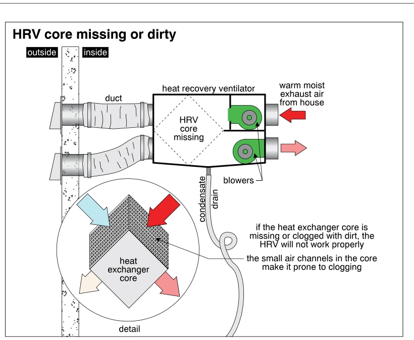
1404HRV core missing or dirty
· p. 256
The illustration shows a heat recovery ventilator connected by two ducts to exterior wall terminations, with two blowers and a condensate drain. A dashed diamond inside the cabinet marks the missing HRV core, and an arro
 1397
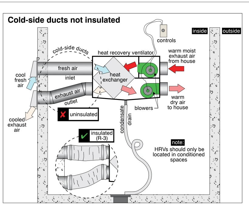
1397Cold-side ducts not insulated
· p. 255
The illustration shows a heat recovery ventilator (HRV) with a heat exchanger, two blowers, controls, and a condensate drain in an interior space. Two cold-side ducts connect the unit to exterior fresh-air intake and exh
 1352
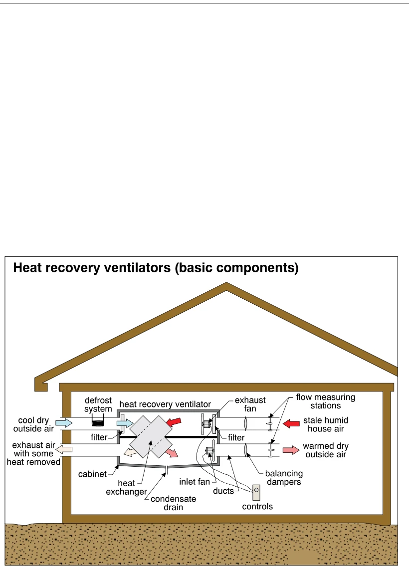
1352Heat recovery ventilators (basic components)
· p. 243
A schematic house contains a heat recovery ventilator connected to outdoor and indoor air ducts. Arrows show cold, dry outside air entering the unit and being delivered indoors as warmed, dry air, while stale, humid hous
 0850
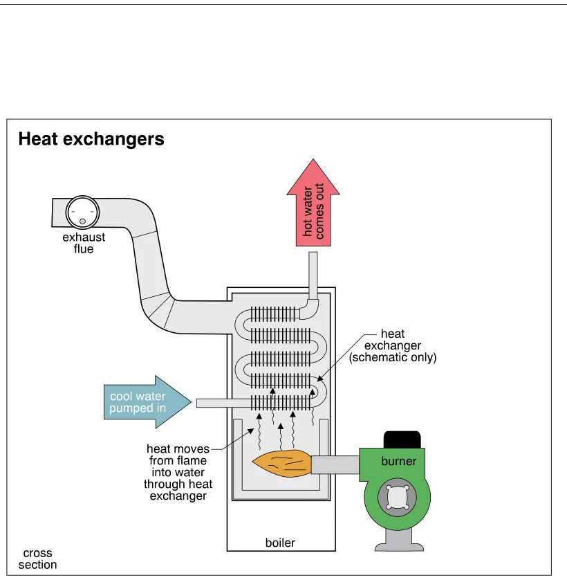
0850Heat exchangers
· p. 143
The illustration shows a schematic cross section of a hot-water boiler with a side-mounted burner firing into the lower combustion chamber. Cool water is pumped into the bottom of a serpentine, finned heat exchanger, and