

Related illustrations
 0901
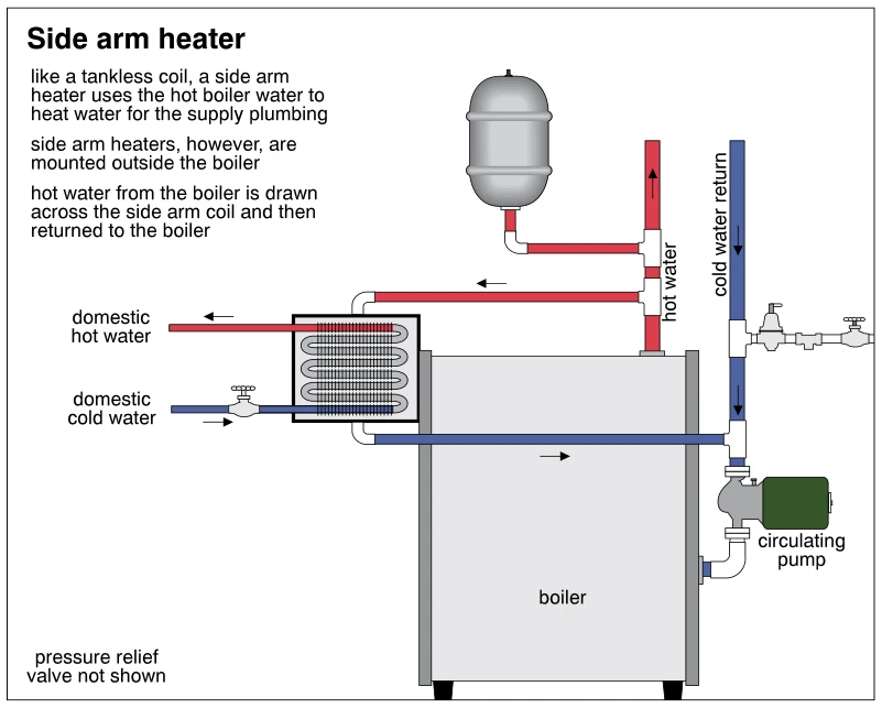
0901Side arm heater
· p. 156
The diagram depicts a hydronic boiler with an externally mounted side arm heater for domestic hot water. Hot boiler water flows from the supply piping through the side arm heater, across the domestic-water coil, and back
 1235
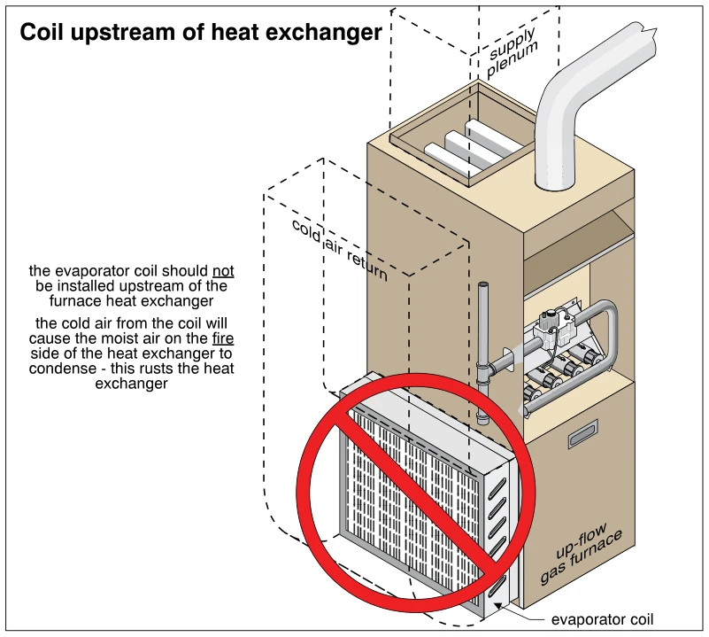
1235Coil upstream of heat exchanger
· p. 218
The illustration shows an up-flow gas furnace with an evaporator coil installed in the cold-air return, upstream of the furnace heat exchanger. Dashed outlines indicate the return duct and the supply plenum above the fur
 0752
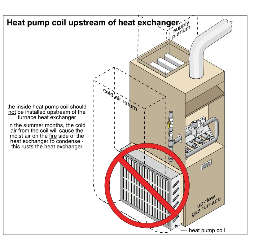
0752Heat pump coil upstream of heat exchanger
· p. 122
The illustration shows an up-flow gas furnace with an indoor heat pump coil installed in the cold-air return, upstream of the furnace heat exchanger. Dashed outlines indicate the return duct and overhead supply plenum, a
 0851
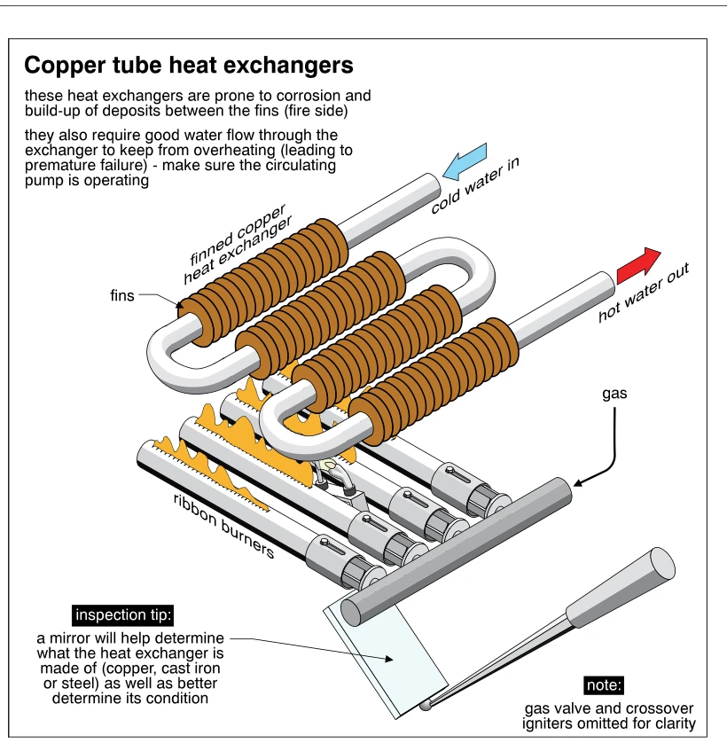
0851Copper tube heat exchangers
· p. 143
The illustration shows a serpentine finned copper heat exchanger positioned above gas-fired ribbon burners in a boiler. Arrows identify cold water entering one end and hot water leaving the other, while a gas supply feed
 0850
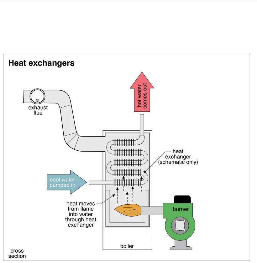
0850Heat exchangers
· p. 143
The illustration shows a schematic cross section of a hot-water boiler with a side-mounted burner firing into the lower combustion chamber. Cool water is pumped into the bottom of a serpentine, finned heat exchanger, and
 0748
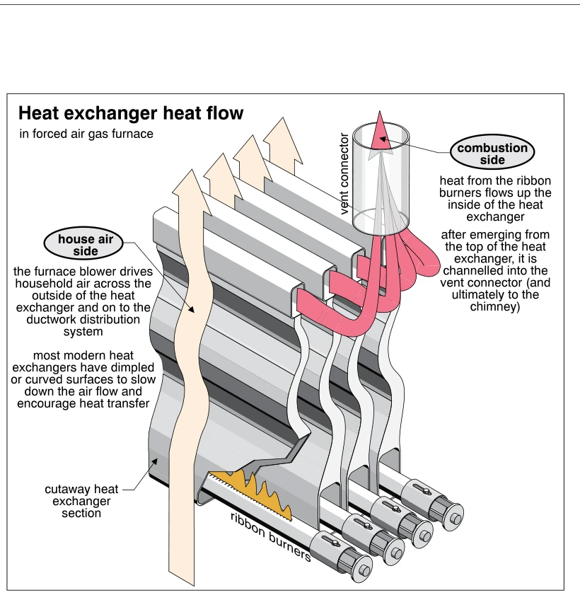
0748Heat exchanger heat flow
· p. 121
The illustration shows a cutaway of a forced-air gas furnace heat exchanger with ribbon burners beneath multiple curved exchanger sections. Pink arrows trace the combustion-side flow upward through the interiors of the s
 0910
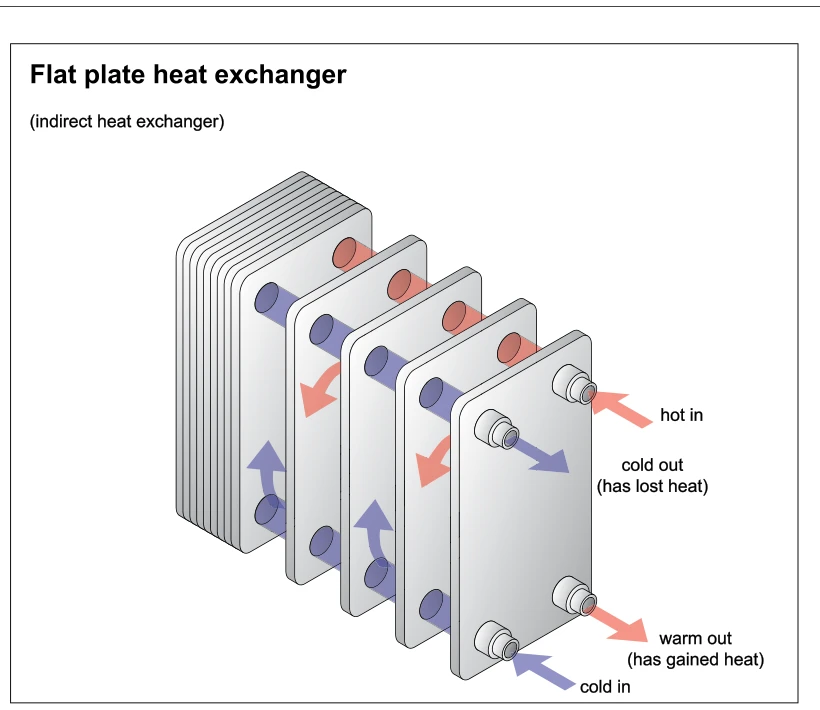
0910Flat plate heat exchanger
· p. 160
An exploded perspective shows a flat plate indirect heat exchanger with a stack of closely spaced plates and four pipe connections on the front plate. Colored arrows illustrate two separate fluid paths through alternatin