
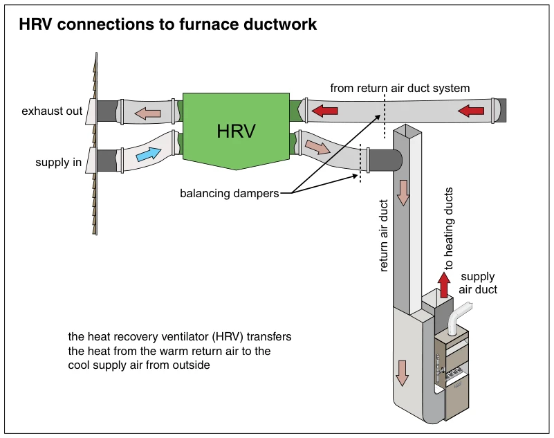
Related illustrations
 1399
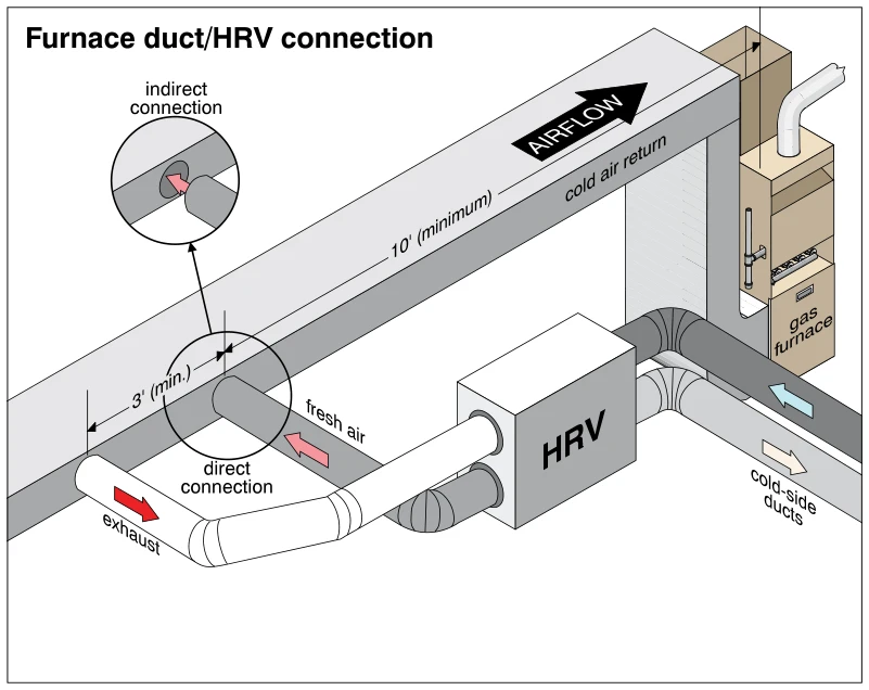
1399Furnace duct/HRV connection
· p. 255
The illustration shows a heat recovery ventilator (HRV) connected to the cold-air return duct of a gas furnace. Arrows show return air moving toward the furnace, fresh air entering the return duct from the HRV, and exhau
 1354
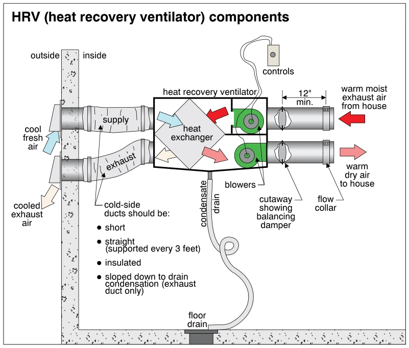
1354HRV (heat recovery ventilator) components
· p. 243
The schematic shows a heat recovery ventilator connected through an exterior wall to fresh-air intake and exhaust ducts, with two additional ducts serving the house. Arrows show cool fresh air passing through the heat ex
 1323
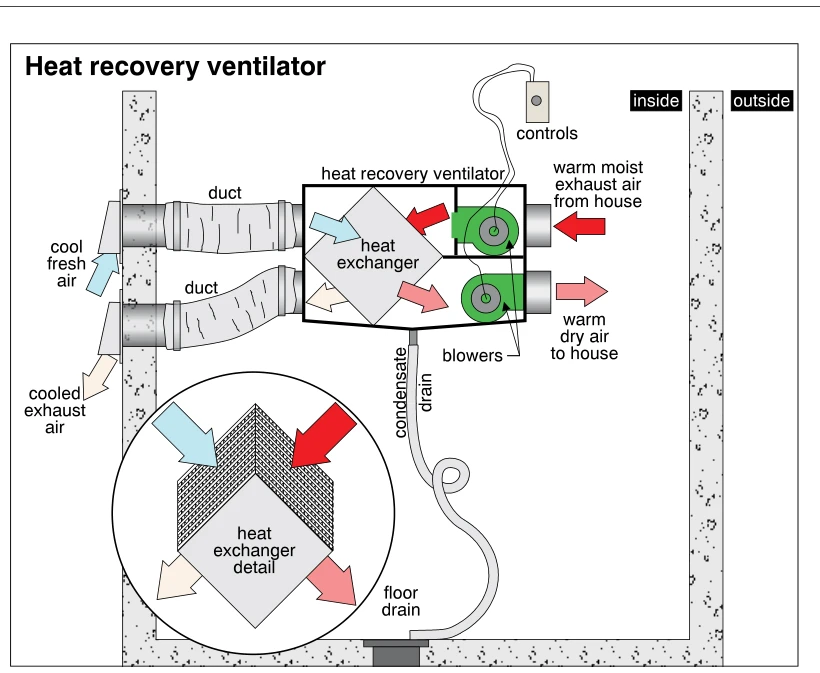
1323Heat recovery ventilator
· p. 236
The illustration shows a heat recovery ventilator with two blowers, a heat exchanger, controls, and ducts passing through an exterior wall. Colored arrows trace cool fresh outdoor air through the exchanger to become warm
 1402
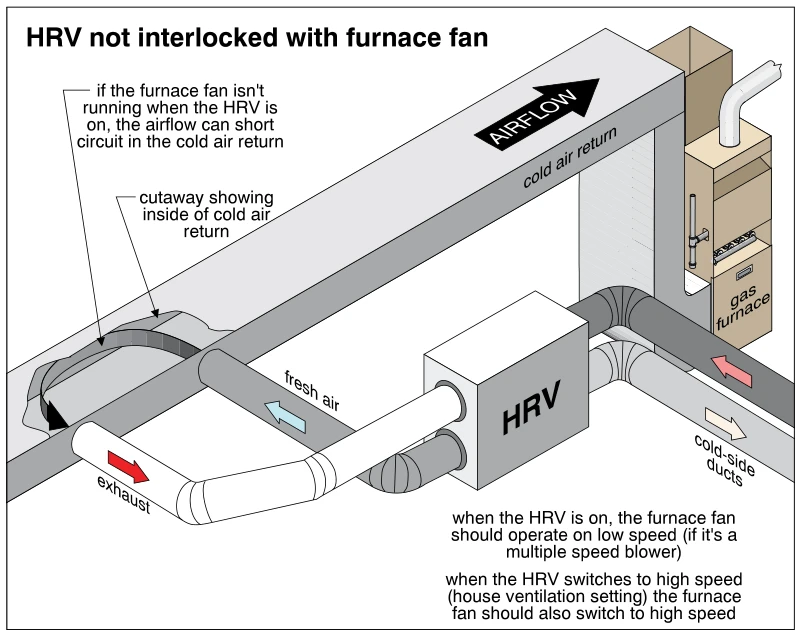
1402HRV not interlocked with furnace fan
· p. 255
The illustration shows a heat recovery ventilator (HRV) connected to the cold-air return duct of a gas furnace, with separate fresh-air and exhaust connections and two cold-side ducts. A cutaway in the return duct shows
 1357.9
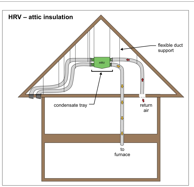
HRV – attic insulation
· p. 245
A house cross-section shows a heat recovery ventilator (HRV) located in a gable attic with flexible ducts connected on both sides. Vertical supports suspend the ductwork from the roof framing, and a condensate tray is po