
05Air Conditioning and Heat Pumps
98 illustrations · printed pages 209-230
Air Conditioning ·The Basicsp. 210
 1200
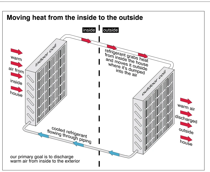
1200Moving heat from the inside to the outside
· p. 210
The illustration shows indoor and outdoor air-conditioning coils connected by refrigerant piping across a dashed inside–outside boundary. Red arrows show warm indoor air entering the indoor coil and refrigerant carrying absorbed heat toward the outdoor coil. At the outdoor coil, red arrows indicate warm air discharged outside the house. Blue arrows on the lower piping show cooled refrigerant returning toward the indoor coil. This is a simplified heat-transfer diagram, with no installation defects depicted.
 1201
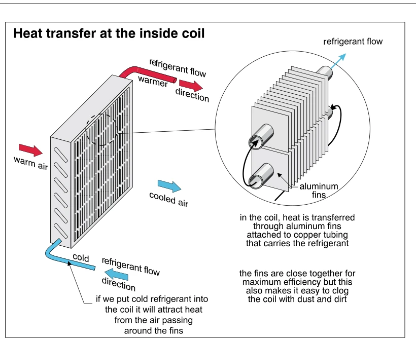
1201Heat transfer at the inside coil
· p. 210
The illustration shows heat transfer at an air-conditioning indoor coil, with warm air entering and cooled air leaving. Cold refrigerant enters the lower connection and exits warmer through the upper connection, as indicated by flow arrows. An enlarged detail shows closely spaced aluminum fins attached to copper tubing carrying the refrigerant. Heat passes from the air through the fins to the refrigerant. An annotation explains that the close fin spacing improves efficiency but makes the coil susceptible to clogging with dust and dirt; no actual clogging is depicted.
 1202
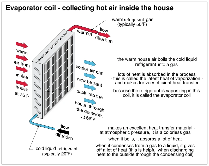
1202Evaporator coil - collecting hot air inside the house
· p. 210
The illustration shows a finned evaporator coil absorbing heat from indoor air. Red arrows indicate house air at 75°F entering the coil, while blue arrows indicate cooled air at 55°F returning to the house through ductwork. Cold liquid refrigerant, labeled typically 20°F, enters at the bottom and leaves at the top as warmer refrigerant gas, labeled typically 50°F. Notes explain that refrigerant vaporization absorbs latent heat and that condensation releases heat at the outdoor condensing coil. No installation defects are depicted.
 1203
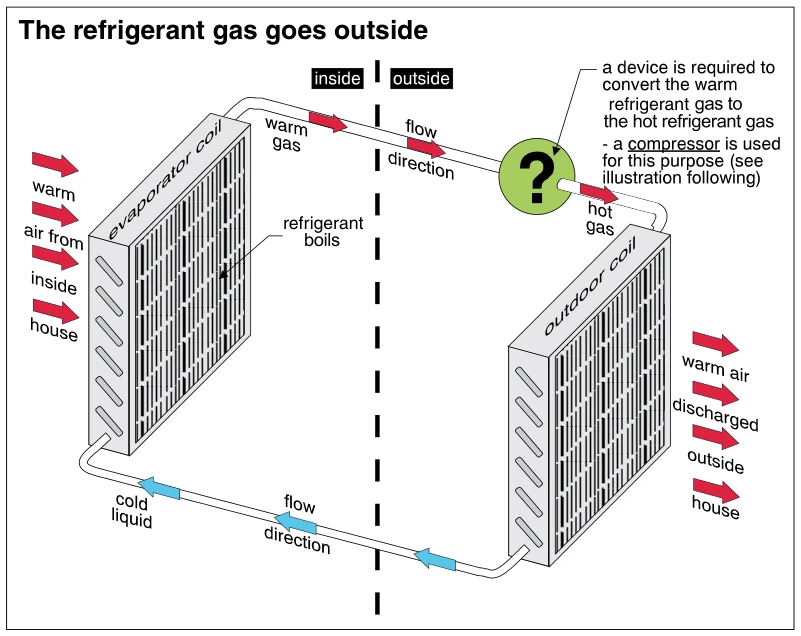
1203The refrigerant gas goes outside
· p. 210
The diagram shows an indoor evaporator coil connected by refrigerant lines to an outdoor coil, with a dashed line separating inside from outside. Warm indoor air passes through the evaporator, where the refrigerant boils, and red arrows show warm refrigerant gas traveling toward the outdoor coil. A question-mark symbol marks the location of a required device, identified in the annotation as a compressor, that converts the warm refrigerant gas to hot gas before it reaches the outdoor coil. Warm air is discharged outside at the outdoor coil, and blue arrows show cold liquid refrigerant returning toward the evaporator.
 1204
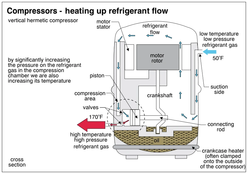
1204Compressors - heating up refrigerant flow
· p. 210
A cross section of a vertical hermetic compressor shows the motor stator and rotor, crankshaft, connecting rod, piston, and compression-area valves inside a sealed housing. Blue arrows trace low-temperature, low-pressure refrigerant gas entering the suction side at 50°F and flowing through the housing toward the compression area. A red arrow shows high-temperature, high-pressure refrigerant gas leaving at 170°F. An annotation explains that increasing refrigerant gas pressure in the compression chamber also increases its temperature. Oil occupies the bottom of the housing, and a crankcase heater is shown clamped around its lower exterior.
 1205
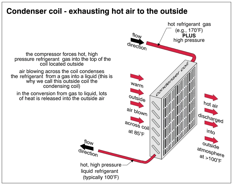
1205Condenser coil - exhausting hot air to the outside
· p. 210
The illustration shows an outdoor air-conditioning condenser coil with refrigerant entering at the top as hot, high-pressure gas and leaving at the bottom as high-pressure liquid. Arrows indicate refrigerant flow through the connecting lines and outside airflow across the finned coil. Incoming outside air is labeled 85°F, while discharged air is labeled greater than 100°F. The annotations explain that heat is released to the outside air as the refrigerant condenses from gas to liquid, with example refrigerant temperatures of 170°F at entry and typically 100°F at exit.
 1206
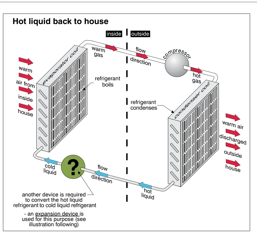
1206Hot liquid back to house
· p. 211
The diagram shows a residential air-conditioning refrigerant circuit divided into inside and outside by a dashed line. Warm indoor air passes through the evaporator coil, where refrigerant boils and leaves as warm gas traveling toward the outdoor compressor. The compressor sends hot gas to the condenser coil, where refrigerant condenses and warm air is discharged outside. Hot liquid refrigerant flows back toward the house, with a question-mark symbol identifying the location where an expansion device is required to produce cold liquid refrigerant before it enters the evaporator. Arrows indicate refrigerant flow and air movement.
 1207
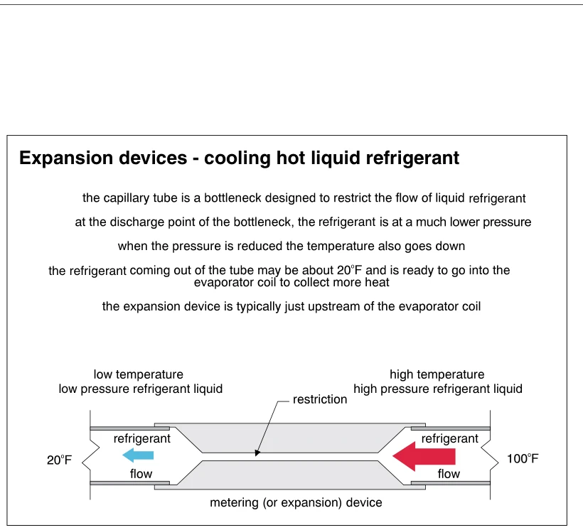
1207Expansion devices - cooling hot liquid refrigerant
· p. 211
A sectional schematic shows refrigerant flowing from right to left through a narrowed passage in a metering or expansion device. The inlet is labeled as high-temperature, high-pressure liquid refrigerant at 100°F, while the outlet is labeled as low-temperature, low-pressure liquid refrigerant at 20°F. Red and blue arrows indicate the flow direction on the hot and cold sides, respectively. Annotations explain that a capillary tube restricts refrigerant flow and that the pressure and temperature decrease after the restriction. The text places the expansion device just upstream of the evaporator coil, which is not shown.
 1208
1208Air conditioning - schematic of system
· p. 211
The schematic depicts a split air-conditioning system with an indoor evaporator coil in a furnace plenum and an outdoor condenser unit containing a compressor, fan, and condensing coil. The furnace blower moves 75°F air through the evaporator coil, with 55°F air leaving above it. A larger suction line carries low-temperature, low-pressure refrigerant gas to the compressor, which discharges high-temperature, high-pressure gas toward the condensing coil. Outdoor air enters at 85°F and leaves at 100°F as heat is rejected. High-pressure liquid refrigerant returns to the indoor expansion device before entering the evaporator at reduced pressure and temperature; the figure notes that temperatures are approximate.
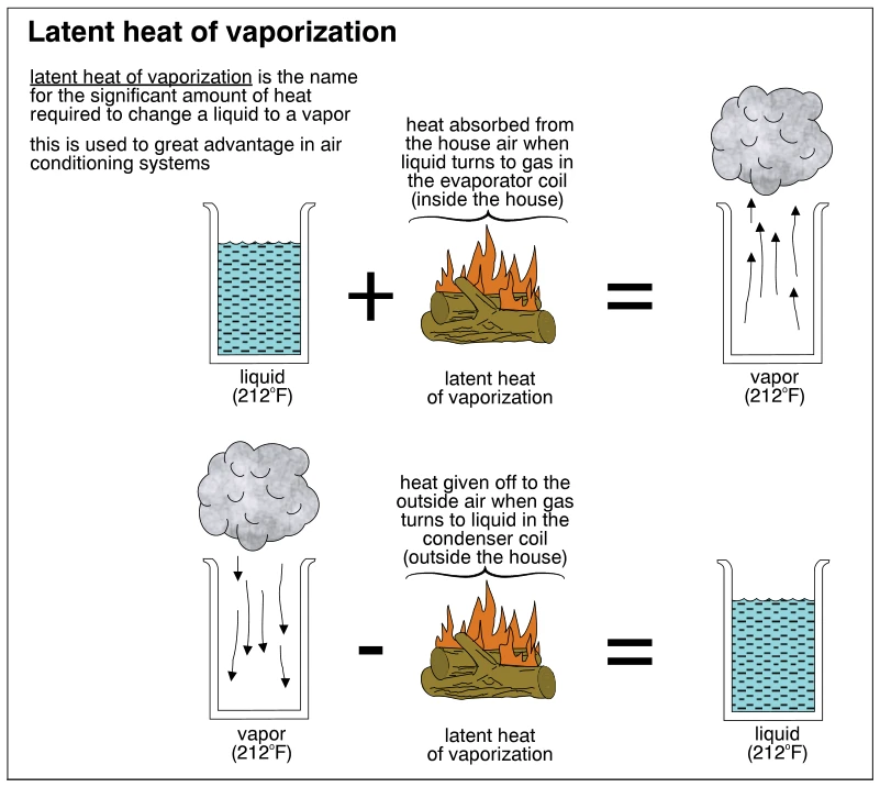 1209
1209Latent heat of vaporization
· p. 211
Two diagrammatic equations illustrate heat transfer during liquid-to-vapor and vapor-to-liquid phase changes. The upper equation shows liquid at 212°F plus latent heat becoming vapor at 212°F, with an annotation relating heat absorption to the indoor evaporator coil. The lower equation shows vapor at 212°F losing latent heat and becoming liquid at 212°F, relating heat rejection to the outdoor condenser coil. Containers, vapor clouds, directional arrows, and fire symbols represent the phase changes and heat exchange; actual air-conditioning equipment is not drawn.
 1210
1210Discharging condensate
· p. 212
A cross section shows an A-shaped evaporator coil in the supply plenum above a furnace heat exchanger and blower. Arrows show return air entering the blower compartment and supply air moving upward through the coil. A condensate tray beneath the coil connects to a line that descends outside the furnace and discharges at a floor drain. A separate perspective view details the coil, tray, and drain line, noting that the tray opening is typically larger than illustrated. The discharge annotation states that no trap is required in some areas and that an air gap is needed at discharge.
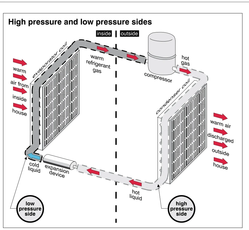 1211
1211High pressure and low pressure sides
· p. 212
The illustration diagrams an air-conditioning refrigerant circuit, with a dashed vertical line separating indoor and outdoor components. Warm indoor air passes toward the evaporator coil, and warm refrigerant gas flows from that coil to the outdoor compressor. Hot gas leaves the compressor and enters the condenser coil, where warm air is discharged outside the house. Refrigerant labeled hot liquid returns toward the expansion device, then enters the evaporator as cold liquid. Arrows indicate flow direction, and callouts identify the low-pressure side near the evaporator inlet and the high-pressure side at the condenser outlet.
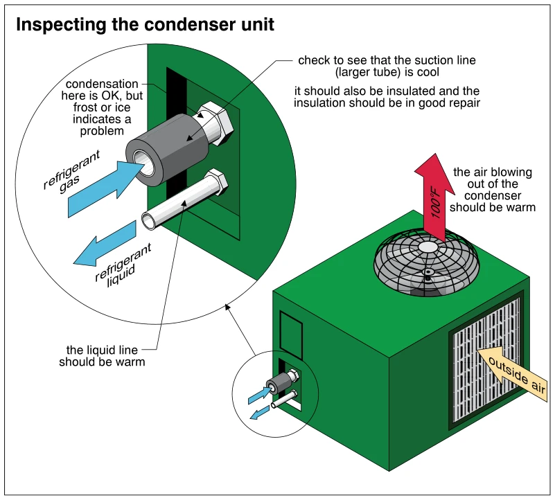 1212
1212Inspecting the condenser unit
· p. 212
The illustration shows an outdoor air-conditioning condenser unit with a top-mounted fan and a side air intake. Arrows indicate outside air entering through the side and warm air discharging upward, with the discharge arrow marked 100°F. An enlarged detail shows refrigerant gas entering through the larger, insulated suction line and refrigerant liquid leaving through the smaller liquid line. The inspection annotations state that the suction line should be cool, its insulation should be in good repair, and the liquid line should be warm. Condensation at the suction connection is identified as acceptable, while frost or ice indicates a problem.
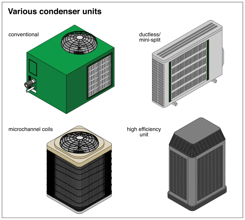 1212.5
Various condenser units
· p. 212
The illustration shows four styles of outdoor air-conditioning condenser units. The conventional unit has a box-shaped cabinet, a top-mounted fan with a protective grille, a side coil grille, and projecting service connections. The ductless/mini-split unit has a shallow rectangular cabinet with a large vertical grille and small mounting feet. The microchannel-coil unit has rounded cabinet corners, wraparound coil surfaces, and a top-mounted fan and guard. The high-efficiency unit has a tall cabinet with screened sides and a sloped, louvered upper section; no defects or installation errors are indicated.
 1213
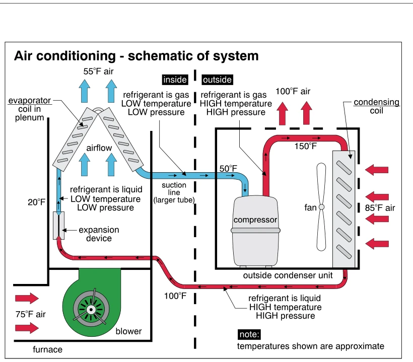
1213Air conditioning - schematic of system
· p. 213
The schematic depicts a split air-conditioning system with an indoor evaporator coil above a furnace blower and an outdoor condenser unit containing a compressor, fan, and condensing coil. Arrows trace refrigerant flow through the compressor, condensing coil, expansion device, and evaporator, with annotations identifying its gas or liquid state and relative temperature and pressure. The larger suction line returns low-temperature, low-pressure gas from the evaporator to the compressor. Indoor air enters at approximately 75°F and leaves the evaporator at 55°F, while outdoor air enters the condenser at 85°F and exits at 100°F. Red and blue refrigerant paths distinguish hotter and colder portions of the cycle; the drawing notes that temperatures are approximate.
 1214
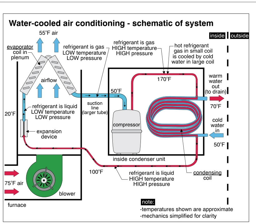
1214Water-cooled air conditioning - schematic of system
· p. 213
The schematic depicts a water-cooled air-conditioning system connected to an evaporator coil in a furnace plenum. A blower moves 75°F air upward through the evaporator, with 55°F air leaving above it. Low-pressure refrigerant gas travels through the larger suction line to the compressor, which sends high-temperature, high-pressure gas to a water-cooled condensing coil. Cold water enters at 50°F, cools the refrigerant through the surrounding coil, and exits toward a drain at 70°F. High-pressure liquid refrigerant returns through an expansion device to the evaporator; arrows indicate flow directions, and the note identifies temperatures as approximate and mechanics as simplified.
 1214.3
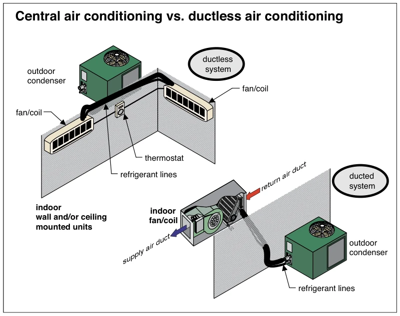
Central air conditioning vs. ductless air conditioning
· p. 213
The illustration compares a ductless mini-split air-conditioning system with a ducted central air-conditioning system. The ductless arrangement shows an outdoor condenser connected by refrigerant lines to two indoor fan/coil units mounted on interior walls, with a thermostat between them. An annotation identifies the indoor units as wall and/or ceiling mounted. The ducted arrangement shows an outdoor condenser connected through a wall to a single indoor fan/coil assembly. Arrows identify return air entering the indoor assembly and supply air leaving through ducts; no defects are depicted.
 1214.6
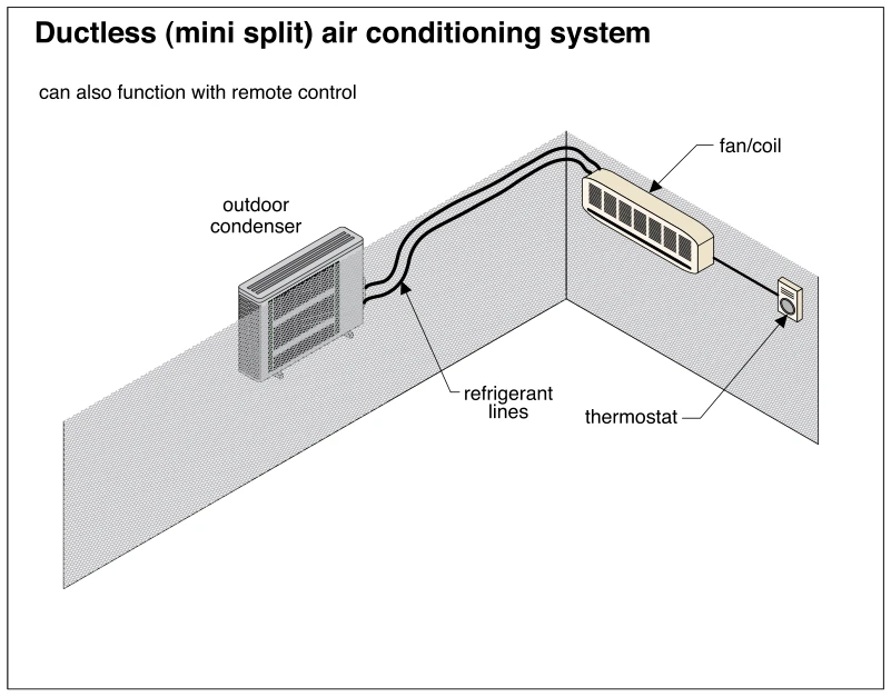
Ductless (mini split) air conditioning system
· p. 213
The illustration depicts a ductless mini-split air conditioning system with an outdoor condenser connected to a wall-mounted indoor fan/coil unit by two refrigerant lines. The lines run along the wall and around a corner to the indoor unit. A wall-mounted thermostat is shown connected to the fan/coil unit, and an annotation notes that the system can also function with remote control. No distribution ductwork or installation defects are depicted.
Air Conditioning ·Air Conditioning Capacityp. 214
 1215
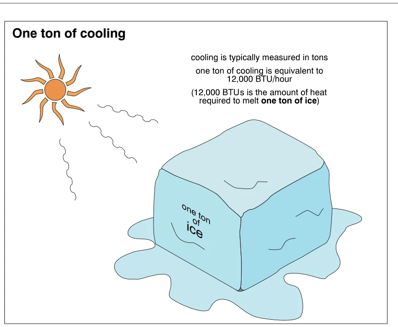
1215One ton of cooling
· p. 214
The illustration shows a block labeled one ton of ice melting into a puddle beneath a sun, with wavy lines representing incoming heat. The annotations explain that cooling capacity is typically measured in tons and that one ton of cooling equals 12,000 BTU/hour. A parenthetical annotation associates 12,000 BTUs with melting one ton of ice, although that statement omits the time basis and is not an accurate total melting-energy value. No air-conditioning equipment or building assembly is depicted.
 1216
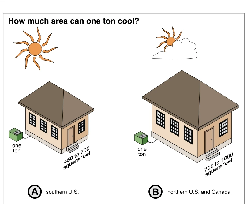
1216How much area can one ton cool?
· p. 214
The illustration compares the floor area served by one ton of air-conditioning capacity in two geographic regions. Panel A shows a smaller house beneath a full sun, labeled southern U.S., with an indicated coverage of 450 to 700 square feet. Panel B shows a larger house beneath a partly cloud-covered sun, labeled northern U.S. and Canada, with an indicated coverage of 700 to 1000 square feet. Each house is connected to an outdoor air-conditioning unit labeled one ton. The comparison illustrates regional differences in cooling coverage rather than an installation defect.
 1217
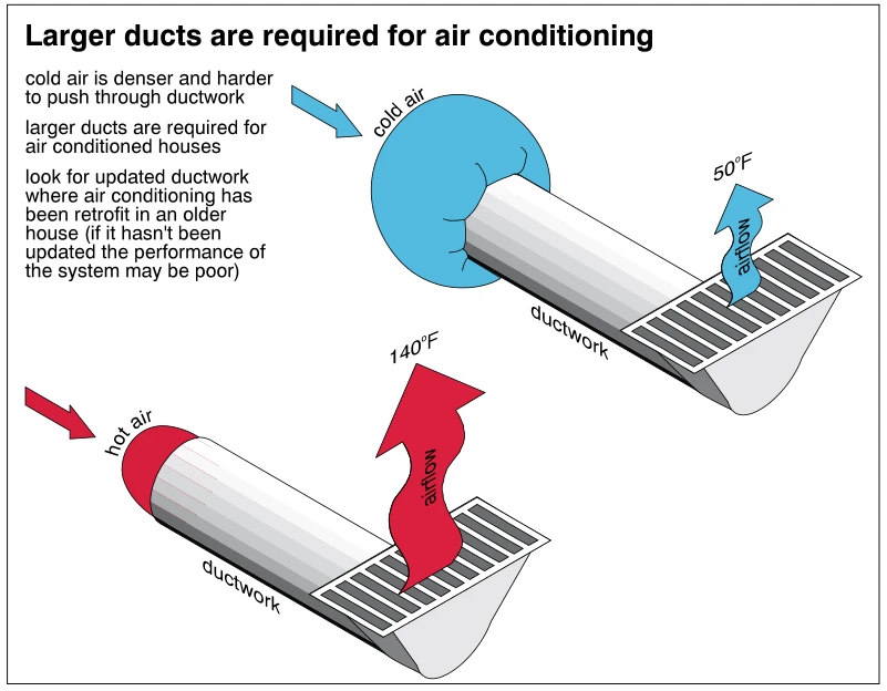
1217Larger ducts are required for air conditioning
· p. 214
The illustration compares cold-air and hot-air delivery through ducts terminating at supply registers. Blue arrows identify cold airflow at 50°F, while red arrows identify hot airflow at 140°F. The cold-air inlet is drawn larger than the hot-air inlet to emphasize the stated need for larger ducts for air conditioning. Annotations explain that cold air is denser and harder to push through ductwork, and advise checking for updated ductwork when air conditioning has been retrofitted into an older house. The stated concern is poor system performance if the ductwork has not been updated.
 1218
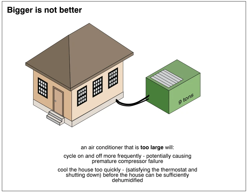
1218Bigger is not better
· p. 214
The illustration shows a house connected to an oversized outdoor air-conditioning unit labeled "9 tons." The unit is drawn disproportionately large to emphasize excessive cooling capacity. The annotations explain that an oversized air conditioner cycles on and off more frequently, potentially causing premature compressor failure. They also explain that rapid cooling satisfies the thermostat and shuts the equipment down before the house is sufficiently dehumidified.
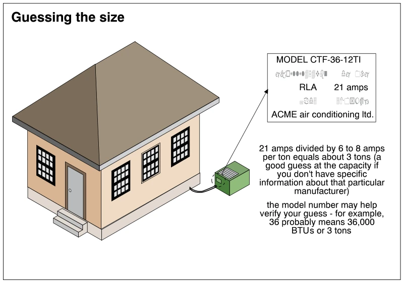 1219
1219Guessing the size
· p. 214
The illustration shows a house connected to an outdoor air-conditioning condensing unit, with an arrow pointing to an enlarged equipment nameplate. The nameplate displays model CTF-36-12TI and an RLA of 21 amps. An annotation estimates cooling capacity at about 3 tons by dividing 21 amps by 6 to 8 amps per ton when manufacturer-specific information is unavailable. Another annotation suggests checking the model number, where 36 may indicate 36,000 BTUs or 3 tons. These are presented as approximate identification methods rather than a definitive capacity determination.
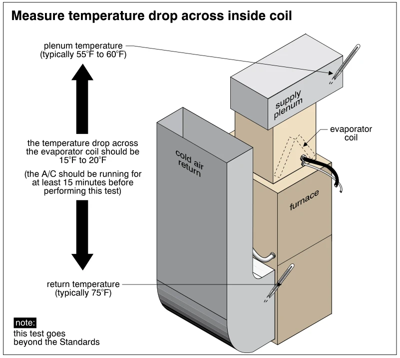 1220
1220Measure temperature drop across inside coil
· p. 214
The illustration shows a furnace with an evaporator coil above it, a supply plenum above the coil, and a cold air return duct connected at the furnace base. Thermometers measure air temperature in the return duct and supply plenum to determine the temperature drop across the indoor coil. Annotations give typical return air temperature as 75°F and supply plenum temperature as 55°F to 60°F, with an expected temperature drop of 15°F to 20°F. The air conditioner should run for at least 15 minutes before this test. A note states that this test goes beyond the Standards.
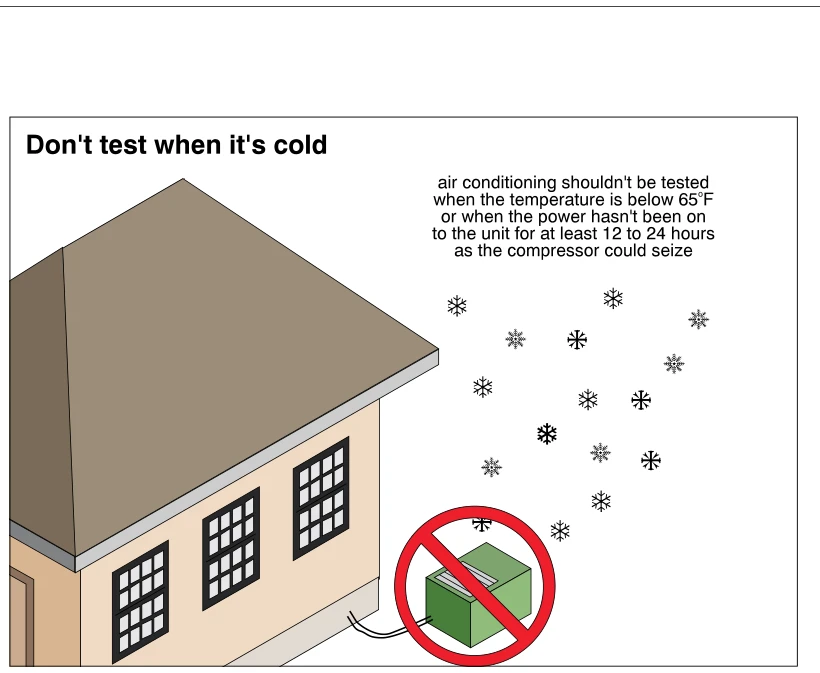 1221
1221Don't test when it's cold
· p. 215
The illustration shows an outdoor air-conditioning condensing unit beside a house, with lines connecting it to the building. Snowflakes indicate cold weather, and a red prohibition symbol overlays the unit. The annotation warns against testing air conditioning below 65°F or when power has not been supplied to the unit for at least 12 to 24 hours. Compressor seizure is identified as a possible consequence of testing under these conditions; no actual compressor damage is shown.
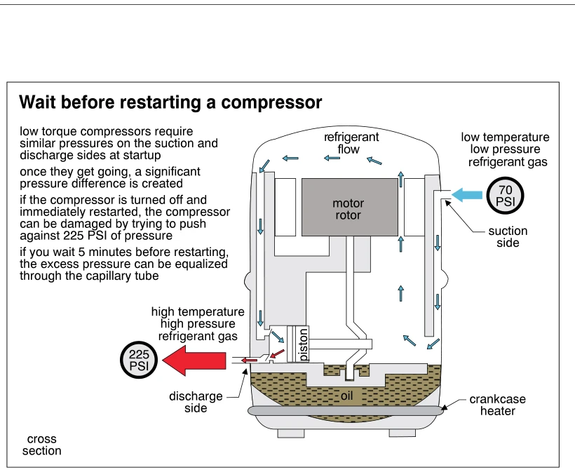 1222
1222Wait before restarting a compressor
· p. 215
A cross section of a refrigerant compressor shows the motor rotor, piston mechanism, oil reservoir, and crankcase heater. Arrows trace low-temperature, low-pressure refrigerant gas entering the suction side at 70 PSI and high-temperature, high-pressure gas leaving the discharge side at 225 PSI. The annotations explain that low-torque compressors require similar suction and discharge pressures at startup and develop a significant pressure difference during operation. Immediately restarting after shutdown can damage the compressor by forcing it to start against high discharge pressure. The illustration recommends waiting five minutes so pressure can equalize through the capillary tube.
 1223
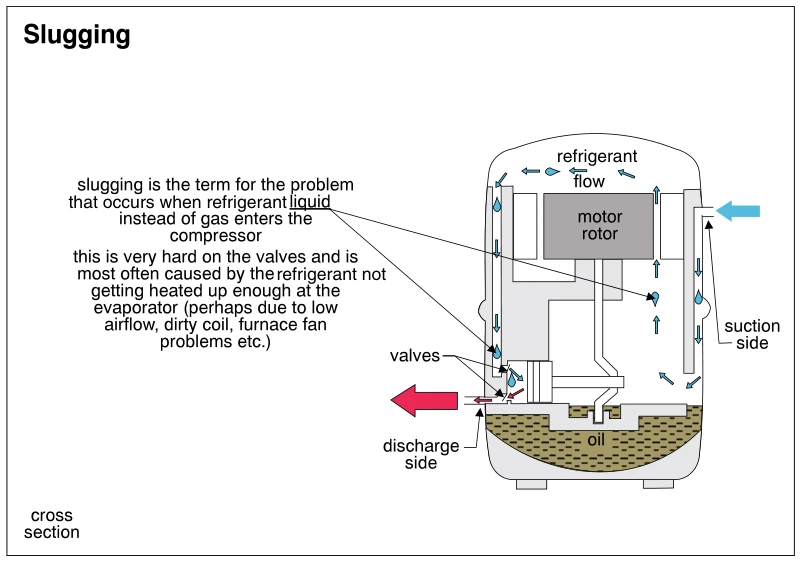
1223Slugging
· p. 215
A cross section of an air-conditioning compressor shows the motor rotor, compressor valves, and an oil sump at the bottom of the housing. Arrows trace refrigerant entering the suction side, circulating through the housing, and leaving the discharge side. Liquid droplets illustrate slugging, in which liquid refrigerant enters the compressor instead of gas, stressing the valves. The annotation links this condition to insufficient heating of refrigerant in the evaporator, potentially caused by low airflow, a dirty coil, or furnace fan problems.
 1224
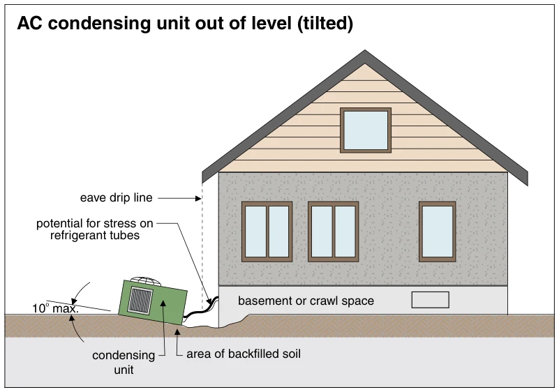
1224AC condensing unit out of level (tilted)
· p. 215
The illustration shows an outdoor air-conditioning condensing unit tilted beside a house foundation. Refrigerant tubes connect the unit to the house, with a callout identifying potential stress on the tubes. The ground beside the foundation is identified as an area of backfilled soil, and the basement or crawl space is shown behind the foundation wall. A dashed vertical line marks the eave drip line near the tubing connection. An angular annotation beside the tilted unit reads "10° max."
 1225
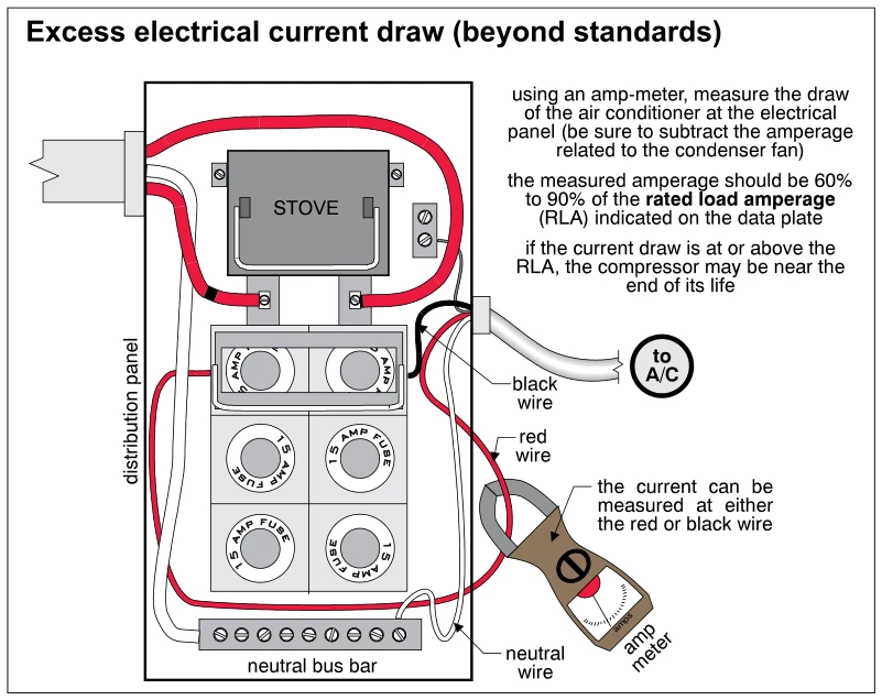
1225Excess electrical current draw (beyond standards)
· p. 215
The illustration shows an open fused electrical distribution panel with a circuit leading to an air conditioner. A clamp-on amp meter surrounds the red conductor, and an annotation identifies either the red or black conductor as a current measurement location. The panel also contains fuse holders, a stove disconnect, and a neutral bus bar. The instructions state that condenser fan amperage should be subtracted from the air conditioner measurement to determine compressor current draw, and give an expected range of 60% to 90% of nameplate rated load amperage (RLA). They warn that current at or above RLA may indicate a compressor nearing the end of its life; no specific measured reading is shown.
 1226
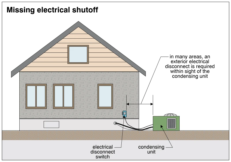
1226Missing electrical shutoff
· p. 215
The illustration shows an outdoor air-conditioning condensing unit beside a house, with lines running between the unit and the exterior wall. A wall-mounted electrical disconnect switch is identified near the unit. A horizontal dimension arrow and annotation emphasize that an exterior electrical disconnect is required within sight of the condensing unit in many areas. Although the title identifies a missing-shutoff defect, the drawing shows the disconnect and its intended relationship to the equipment.
Air Conditioning ·Condenser Coil (Outdoor Coil)p. 216
 1226.3
Scroll compressor schematic
· p. 216
The illustration shows a cutaway of a scroll compressor with a motor and crankshaft below the fixed and orbiting scroll assembly. Arrows indicate flow into the lower suction tube and out through the upper discharge connection, where a discharge thermostat is identified. Counterweights and heavy duty ball bearings are shown around the shaft, with an oil pump extending into the oil reservoir at the bottom of the housing. A separate plan view shows the interleaved fixed and orbiting scrolls, with curved arrows indicating motion. The schematic explains compressor construction without depicting defects.
 1226.6
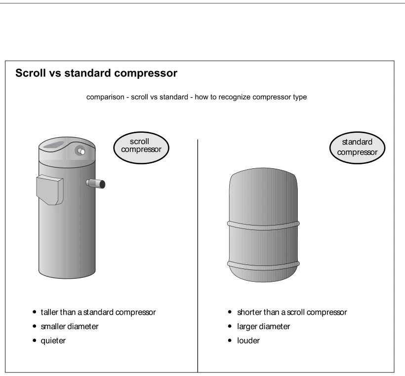
Scroll vs standard compressor
· p. 216
The illustration compares the exterior appearance of scroll and standard air-conditioning compressors side by side. The scroll compressor is shown as a tall, narrow cylindrical housing with a side-mounted electrical connection cover and projecting pipe connection. The standard compressor has a shorter, wider housing with rounded ends and two circumferential bands. Annotations identify the scroll compressor as quieter and the standard compressor as louder; no defects or improper installations are depicted.
 1227
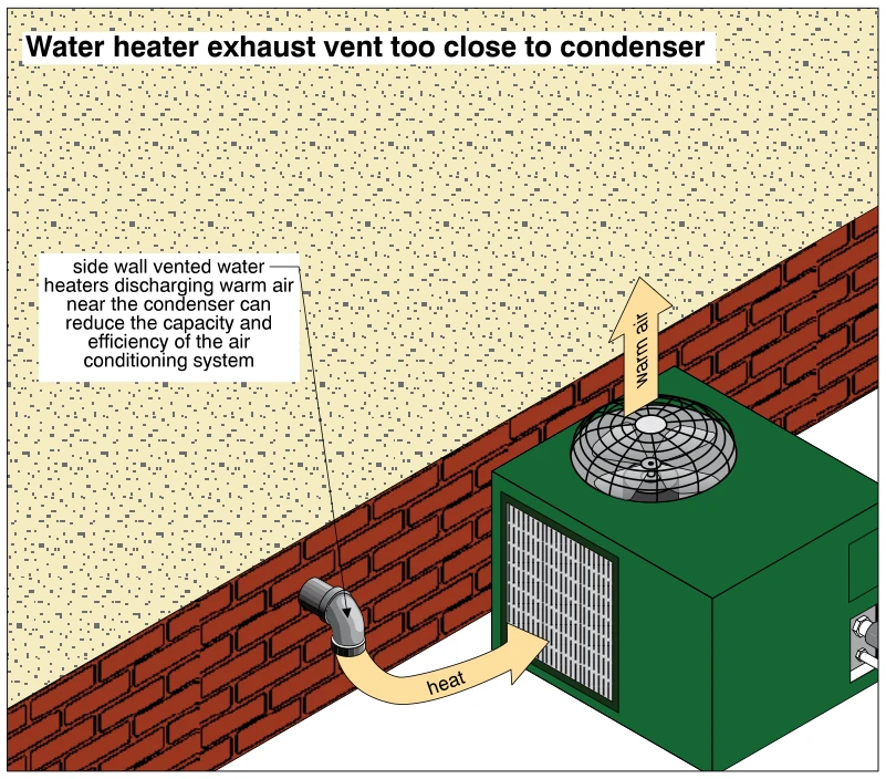
1227Water heater exhaust vent too close to condenser
· p. 216
An outdoor air-conditioning condenser is positioned beside an exterior wall near a sidewall water-heater exhaust vent. The vent terminates in a downward-facing elbow adjacent to the condenser coil grille. A curved arrow labeled "heat" shows exhaust heat directed toward the coil, while an upward arrow indicates warm air discharged through the condenser's top-mounted fan. The illustration identifies this vent placement as improper because warm exhaust near the condenser can reduce air-conditioning capacity and efficiency.
 1228
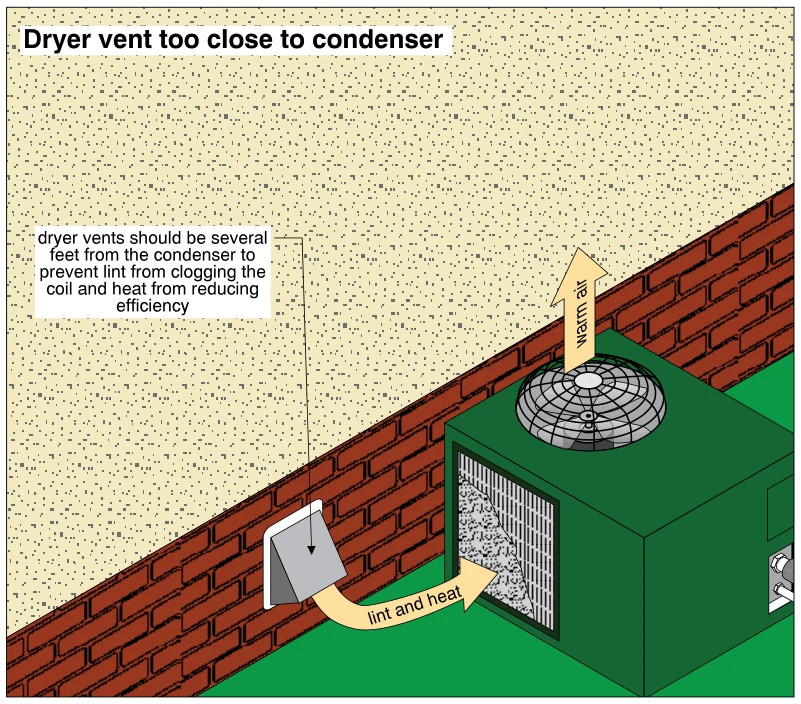
1228Dryer vent too close to condenser
· p. 216
An outdoor air-conditioning condenser is located beside a brick exterior wall, immediately adjacent to a hooded dryer exhaust vent. An arrow shows lint and heat from the dryer vent flowing toward the condenser's side coil, where accumulated debris is illustrated. A top-mounted fan discharges warm air upward. The annotation recommends separating dryer vents from condensers by several feet to prevent coil clogging and reduced efficiency.
Air Conditioning ·Evaporator Coil (Indoor Coil)p. 217
 1229
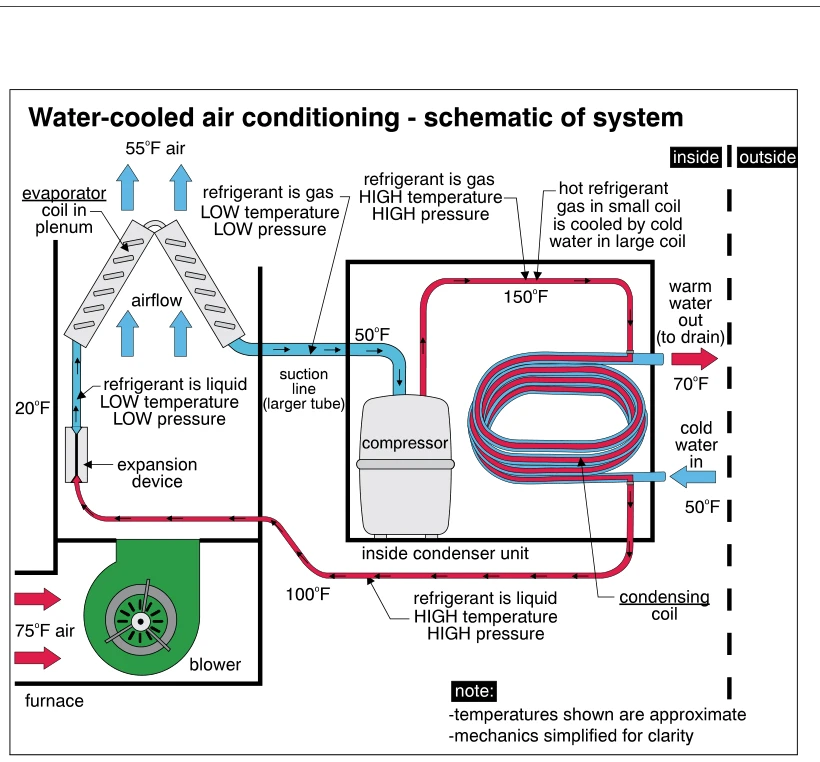
1229Water-cooled air conditioning - schematic of system
· p. 217
The schematic depicts a water-cooled air-conditioning system connected to an evaporator coil in a furnace plenum. A blower moves 75°F air upward through the evaporator, with cooled air leaving at 55°F. Low-temperature, low-pressure refrigerant gas travels through the larger suction line to the compressor, which sends high-temperature, high-pressure gas to the condensing coil. Cold water flowing through the larger coil cools refrigerant in the smaller coil, with water entering at 50°F and discharging warm to a drain at 70°F. High-pressure liquid refrigerant returns through an expansion device to the evaporator; arrows indicate flow directions, and the drawing notes that temperatures are approximate and mechanics are simplified.
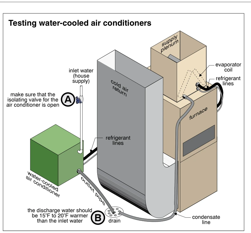 1230
1230Testing water-cooled air conditioners
· p. 217
The illustration shows a water-cooled air conditioner connected by refrigerant lines to an evaporator coil in the supply plenum above a furnace. A large cold-air return duct runs alongside the furnace. House-supply water enters the water-cooled unit through an isolating valve, and an outlet pipe discharges water to a floor drain. Test annotation A instructs that the isolating valve be open, while annotation B states that discharge water should be 15°F to 20°F warmer than inlet water. A separate condensate line from the evaporator coil also runs to the drain.
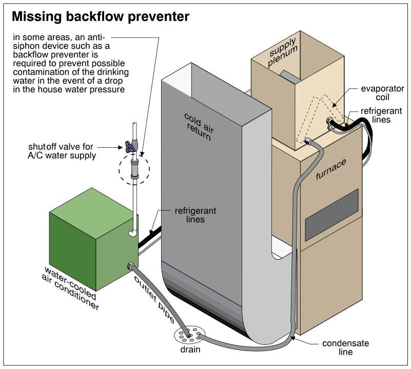 1231
1231Missing backflow preventer
· p. 217
The illustration shows a water-cooled air conditioner connected by refrigerant lines to an evaporator coil in the supply plenum above a furnace. A large cold-air return duct runs beside the furnace, and a condensate line leads from the coil area to a floor drain. The air conditioner has a water supply with a shutoff valve and an outlet pipe discharging to the drain. A dashed circle highlights the missing backflow preventer on the water supply. The annotation explains that an anti-siphon device is required in some areas to prevent drinking-water contamination if house water pressure drops.
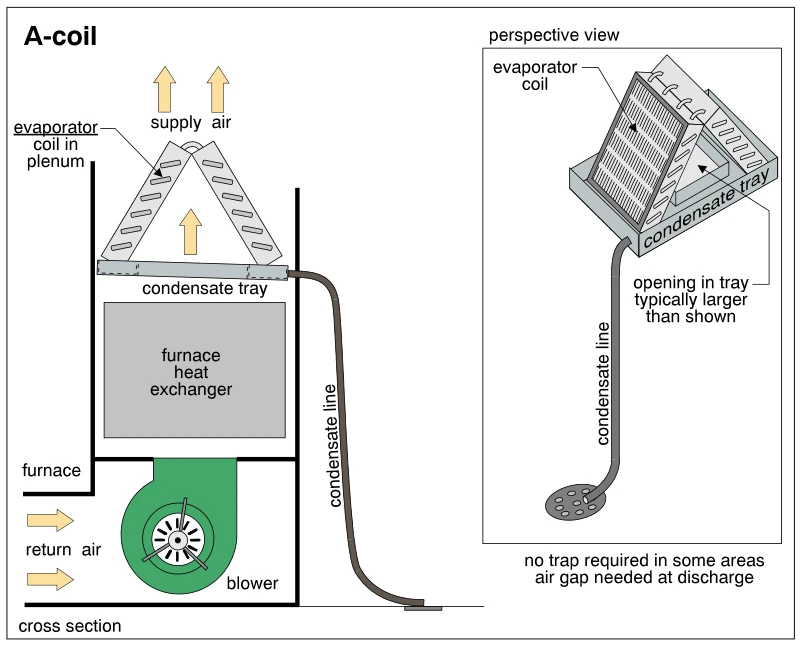 1232
1232A-coil
· p. 217
The cross section shows an A-shaped evaporator coil in the supply plenum above a furnace heat exchanger. A blower draws return air into the bottom of the furnace and moves it upward through the heat exchanger and coil to become supply air. A condensate tray beneath the coil connects to a condensate line routed down to a drain. The perspective view shows the two sloping coil sections, the surrounding tray, and its central airflow opening, noted as typically larger than shown. An annotation states that no trap is required in some areas and that an air gap is needed at discharge.
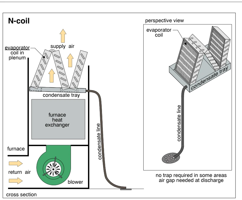 1232.5
N-coil
· p. 218
The illustration shows cross-sectional and perspective views of an N-shaped indoor evaporator coil. In the cross section, a furnace blower moves return air upward through the furnace heat exchanger and the evaporator coil in the supply plenum. Three inclined coil sections form the N configuration above a condensate tray. A condensate line carries collected water from the tray to a drain. The perspective-view annotation notes that no trap is required in some areas and that an air gap is needed at discharge.
 1233
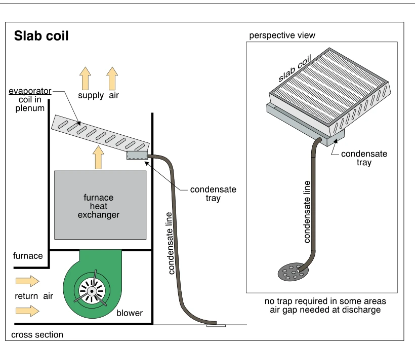
1233Slab coil
· p. 218
The cross section shows an inclined slab evaporator coil in the supply plenum above a furnace heat exchanger. A blower draws return air into the furnace and pushes it upward through the heat exchanger and coil to become supply air. A condensate tray at the lower edge of the coil connects to a condensate line that extends down to a drain. The perspective view shows the finned slab coil, its collection tray, and the drain line discharging above a floor drain. An annotation states that no trap is required in some areas and that an air gap is needed at discharge.
 1234
1234Attic evaporator coil
· p. 218
The illustration shows an enclosed attic evaporator coil with return and supply ductwork, with arrows indicating airflow into and out of the unit. A primary condensate line connects to the unit and includes a trap; its condensate tray is identified as typically built into the unit. An auxiliary condensate tray beneath the enclosure has a separate drain line labeled as having no trap. The primary drain discharge options are listed, while the auxiliary drain is directed to a conspicuous location, such as outdoors above a window or door. A note identifies PVC as the typical condensate drain material.
 1235
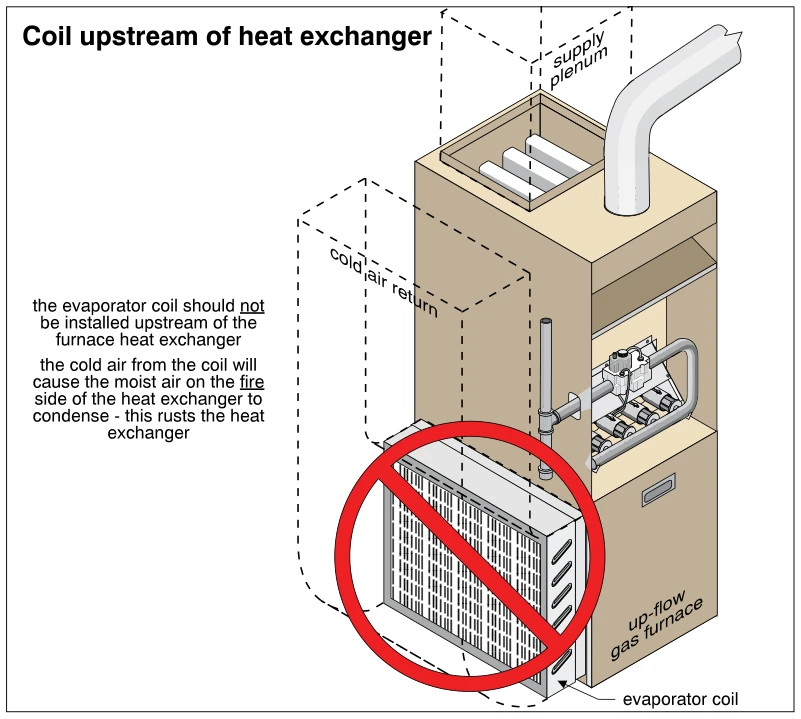
1235Coil upstream of heat exchanger
· p. 218
The illustration shows an up-flow gas furnace with an evaporator coil installed in the cold-air return, upstream of the furnace heat exchanger. Dashed outlines indicate the return duct and the supply plenum above the furnace. A cutaway exposes the furnace burners and gas piping, while a vent pipe extends from the top. A red prohibition symbol over the coil identifies this placement as improper. The annotations explain that cold air from the coil causes moisture on the fire side of the heat exchanger to condense, leading to rust.
Air Conditioning ·Condensate Systemp. 219
 1236
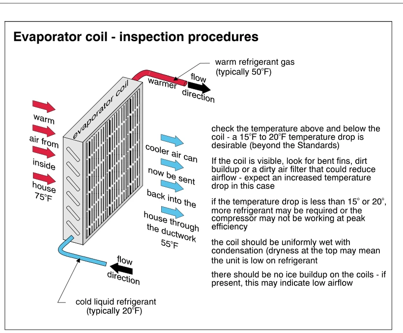
1236Evaporator coil - inspection procedures
· p. 219
The illustration shows a finned evaporator coil with warm indoor air entering at 75°F and cooled air leaving at 55°F for return to the house through ductwork. Blue and red refrigerant lines indicate cold liquid refrigerant entering the bottom of the coil and warmer refrigerant gas leaving the top, with arrows identifying flow direction. Inspection notes recommend checking the air temperature drop across the coil and looking for bent fins, dirt buildup, or a dirty air filter that could restrict airflow. Additional notes discuss inadequate cooling, nonuniform condensation, and ice buildup as possible indicators of refrigerant, compressor, or airflow problems. These conditions are described as inspection checks rather than visibly illustrated damage.
 1237
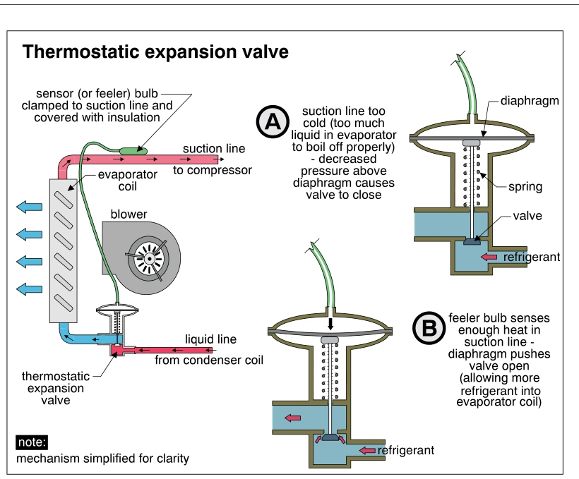
1237Thermostatic expansion valve
· p. 219
The illustration shows a thermostatic expansion valve controlling refrigerant flow from the condenser liquid line into an evaporator coil, with a blower moving air across the coil. A sensor bulb clamped to the suction line and covered with insulation connects to the valve diaphragm through a small tube. Cutaway A shows decreased pressure above the diaphragm closing the valve when the suction line is too cold and too much liquid remains in the evaporator to boil off properly. Cutaway B shows bulb pressure pushing the diaphragm and opening the valve when the suction line has enough heat, admitting more refrigerant to the evaporator. Arrows indicate refrigerant flow, and the valve mechanism is explicitly simplified for clarity.
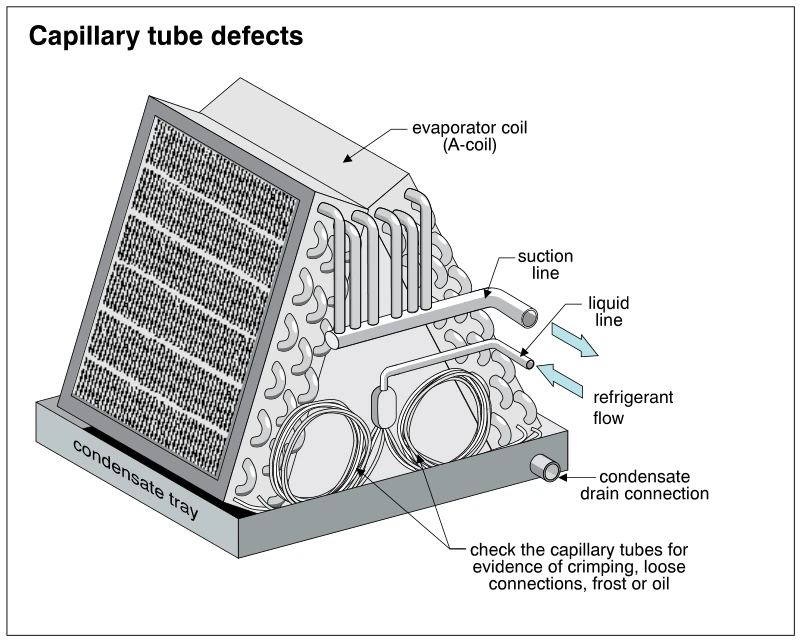 1238
1238Capillary tube defects
· p. 219
The illustration shows an air-conditioning evaporator A-coil seated in a condensate tray with a side drain connection. The exposed end of the coil shows refrigerant tubing, coiled capillary tubes, and connections to the liquid and suction lines. Arrows indicate refrigerant entering through the liquid line and leaving through the suction line. An inspection annotation directs attention to the capillary tubes for evidence of crimping, loose connections, frost, or oil; no specific damaged location is clearly depicted.
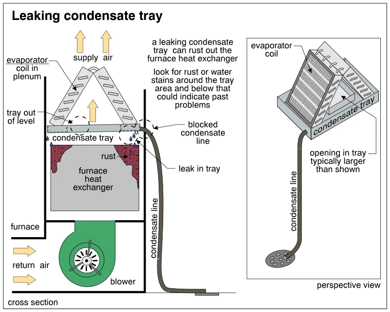 1239
1239Leaking condensate tray
· p. 219
The cross section shows an A-shaped air-conditioning evaporator coil and condensate tray above a furnace heat exchanger, with a blower below directing return air upward into the supply plenum. The tray is identified as out of level, the condensate line as blocked, and a leak is shown dripping onto the heat exchanger. Rust is depicted on both upper sides of the heat exchanger, illustrating damage from condensate leakage. An annotation advises looking for rust or water stains around and below the tray as evidence of past problems. A separate perspective view shows the evaporator coil seated in its condensate tray, with a condensate line extending down to a floor drain.
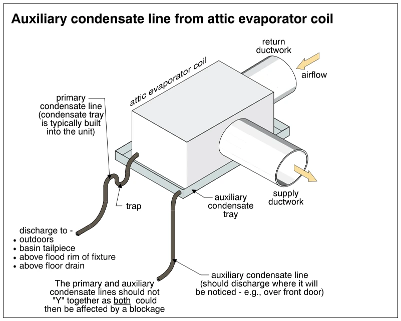 1240
1240Auxiliary condensate line from attic evaporator coil
· p. 219
The illustration shows an attic evaporator coil housing connected to return and supply ductwork, with arrows indicating airflow through the unit. A trapped primary condensate line drains the unit's internal condensate tray, with several possible discharge locations listed. An auxiliary condensate tray beneath the housing has its own separate drain line, which is to discharge where occupants will notice it, such as over the front door. An annotation warns against joining the primary and auxiliary lines with a Y connection because a blockage could affect both.
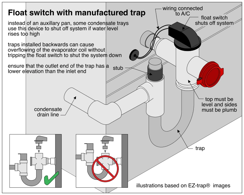 1240.5
Float switch with manufactured trap
· p. 219
The illustration shows a manufactured air-conditioning condensate trap with an integral float switch wired to shut down the system when the water level rises too high. A U-shaped trap connects the taller inlet assembly, which carries the float switch and a side access cap, to the lower outlet and condensate drain line. The outlet side includes a capped stub. Annotations specify that the top must be level, the sides plumb, and the outlet lower than the inlet. Two inset diagrams compare correct installation with a reversed installation, warning that a backward trap can allow overflow at the evaporator coil without activating the float switch.
Air Conditioning ·Refrigerantp. 220
 1241
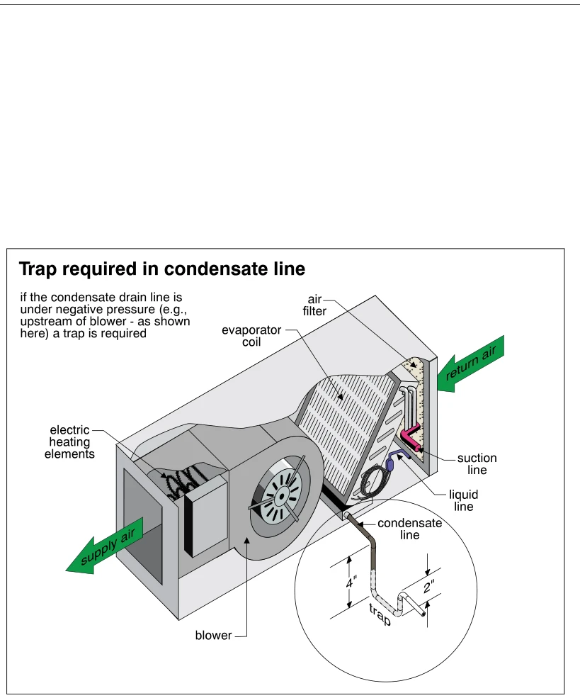
1241Trap required in condensate line
· p. 220
A cutaway air handler shows return air entering through an air filter and evaporator coil before reaching the blower and electric heating elements, then exiting as supply air. Refrigerant suction and liquid lines connect to the evaporator coil. A condensate drain line leaves the coil area and drops into a trap, highlighted in an enlarged circular detail with 4-inch and 2-inch vertical dimensions. The annotation states that a trap is required when the condensate drain is under negative pressure, as in this arrangement with the coil upstream of the blower.
 1242
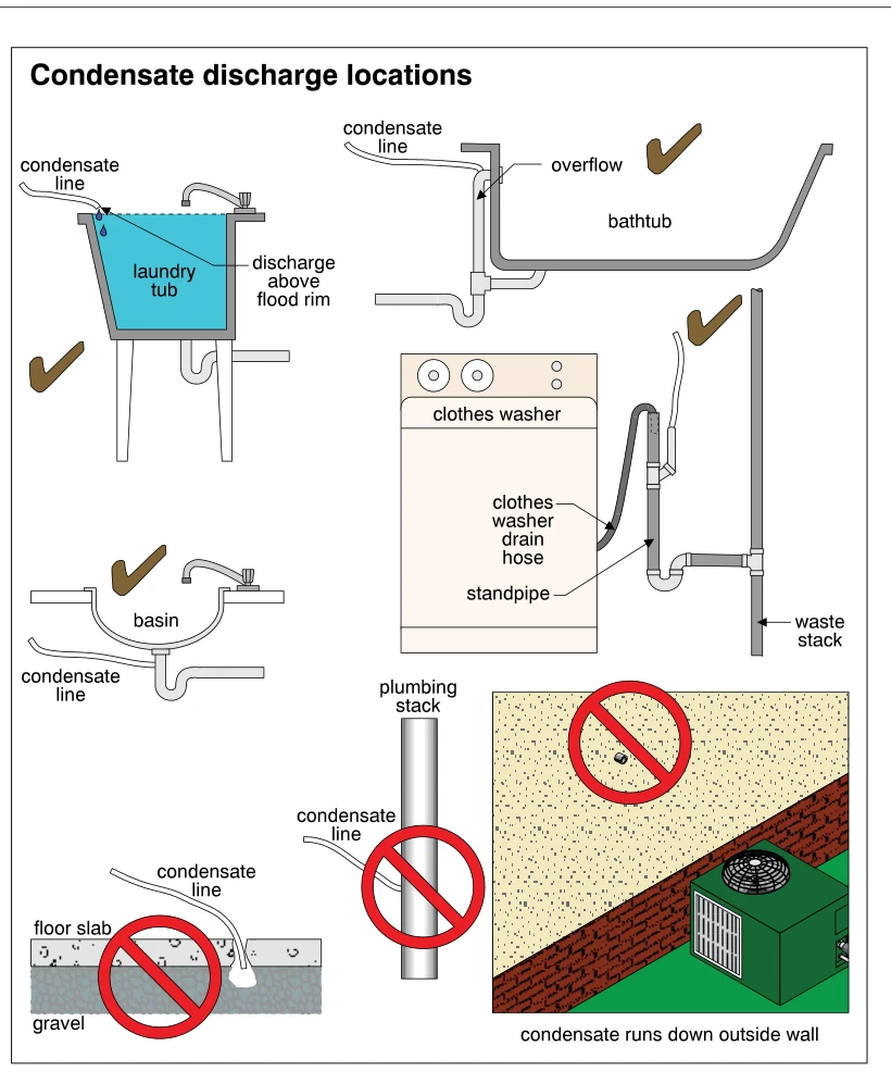
1242Condensate discharge locations
· p. 220
The illustration compares acceptable and unacceptable air-conditioning condensate discharge locations using check marks and prohibition symbols. Checked arrangements show discharge above a laundry tub's flood rim, into a bathtub overflow, into a basin drain upstream of its trap, and into a clothes-washer standpipe arrangement. The washer drain hose, trapped standpipe, and connection to a waste stack are shown together. Prohibited arrangements show condensate discharged into gravel beneath a floor slab, connected directly to a plumbing stack, and running down an exterior wall near an outdoor air-conditioning unit.
 1243
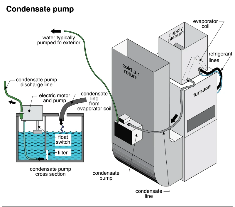
1243Condensate pump
· p. 220
The illustration shows an air-conditioning evaporator coil above a furnace, with adjacent cold-air return ductwork and a supply plenum. A condensate line carries water from the evaporator coil to a condensate pump mounted beside the return duct. The pump discharge line rises upward, with an arrow indicating that water is typically pumped to the exterior. An enlarged pump cross section shows the water reservoir, electric motor and pump, float switch, and filter, with arrows indicating water flow. No defect or improper installation is identified.
 1244
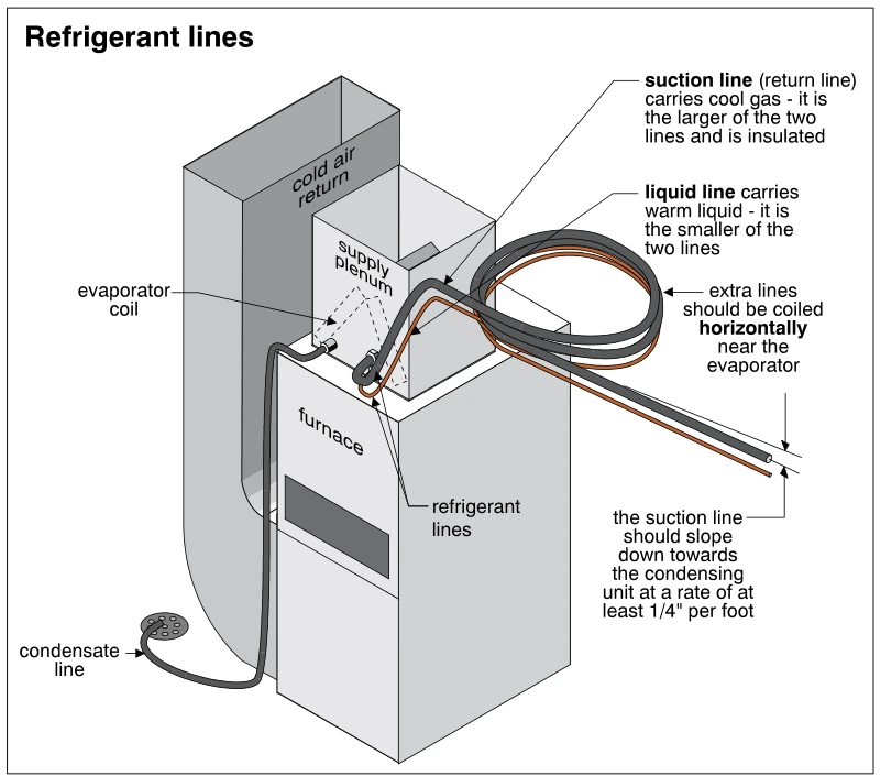
1244Refrigerant lines
· p. 220
The illustration shows refrigerant lines connected to an evaporator coil in the supply plenum above a furnace, with a cold air return duct alongside. The larger, insulated suction line carries cool gas, while the smaller liquid line carries warm liquid. Excess refrigerant tubing is shown coiled horizontally near the evaporator. An annotation specifies that the suction line should slope downward toward the condensing unit at least 1/4 inch per foot. A separate condensate line runs from the coil area to a floor drain.
Air Conditioning ·Evaporator Fan (Indoor Fan)p. 221
 1245
1245Filter/dryer
· p. 221
The illustration shows an outdoor air-conditioning condensing unit with a top-mounted fan, side coil grille, and two connected refrigerant lines. A filter/dryer is installed in the smaller liquid line, with refrigerant flow indicated away from the condenser. Airflow arrows show outside air entering the side of the unit and warm air discharging upward. Annotations explain filter/dryer placement, use after compressor replacement, and typical cotton filter and silica gel contents. A callout identifies frost accumulation just past the filter/dryer as a possible sign of partial plugging and instructs that any directional arrow on the filter/dryer must point away from the condenser.
 1246
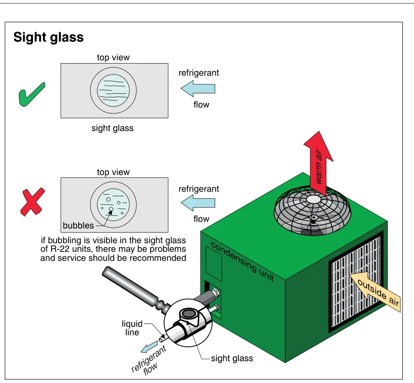
1246Sight glass
· p. 221
The illustration shows a refrigerant sight glass installed in the liquid line adjacent to an outdoor air-conditioning condensing unit. An enlarged detail identifies the sight glass and the direction of refrigerant flow. Two top views compare refrigerant without visible bubbles, marked with a green check, with bubbling refrigerant, marked with a red X. The annotation states that visible bubbling in the sight glass of R-22 units may indicate problems and warrants a service recommendation. Airflow arrows show outside air entering the condenser coil and warm air discharging upward through the top-mounted fan.
 1247
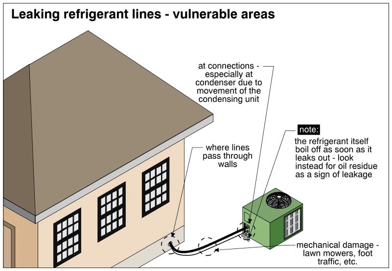
1247Leaking refrigerant lines - vulnerable areas
· p. 221
The illustration shows refrigerant lines running from a house wall to an outdoor air-conditioning condensing unit. Callouts identify vulnerable leakage locations at the wall penetration and at connections, particularly where movement of the condensing unit can affect the lines. The exposed run near ground level is identified as susceptible to mechanical damage from lawn mowers and foot traffic. A note explains that refrigerant boils off when it escapes and that oil residue should be sought as evidence of leakage.
 1248
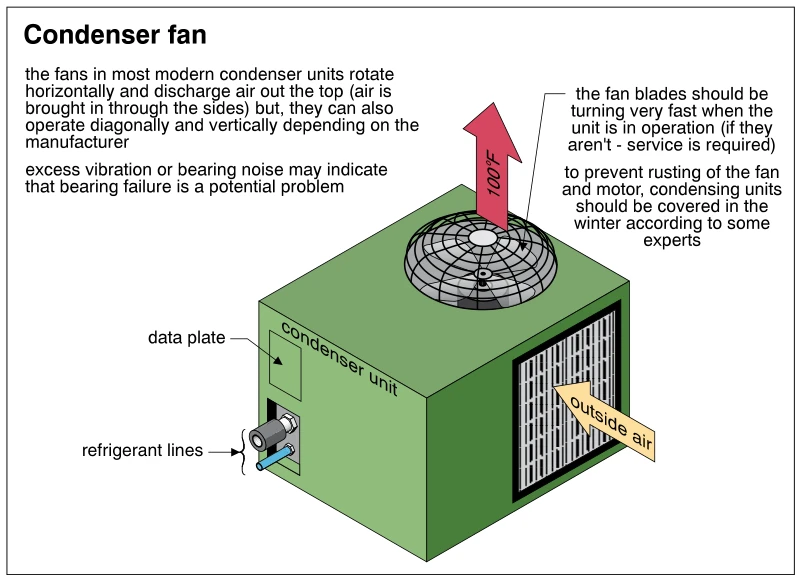
1248Condenser fan
· p. 221
The illustration depicts an outdoor air-conditioning condenser unit with a top-mounted fan beneath a protective grille. Arrows show outside air entering through the side coil and heated air discharging upward, labeled 100°F. Refrigerant lines and a data plate are identified on the adjacent cabinet face. Notes describe typical fan orientation and identify excessive vibration, bearing noise, or inadequate fan speed as potential service concerns. Another annotation presents winter covering as a rust-prevention recommendation attributed to some experts; no actual damage is depicted.
 1249
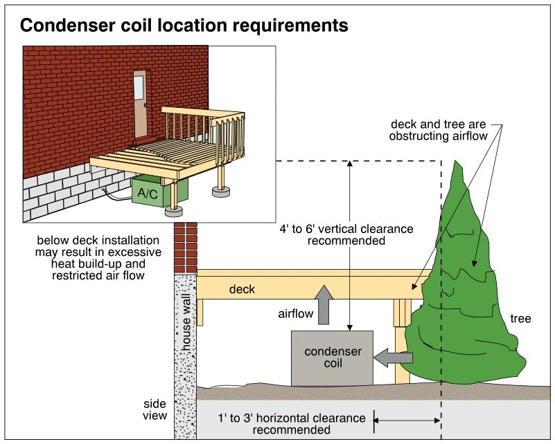
1249Condenser coil location requirements
· p. 221
The illustration shows an outdoor air-conditioning condenser installed beneath a deck beside a house wall, with a tree close to its side. A side view uses arrows to show horizontal airflow into the condenser and upward discharge toward the deck. The deck and tree are identified as airflow obstructions, and the inset warns that below-deck installation may cause excessive heat buildup and restricted airflow. Dimension arrows indicate recommended clearances of 4 to 6 feet vertically and 1 to 3 feet horizontally.
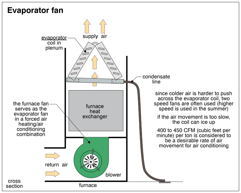 1250
1250Evaporator fan
· p. 221
The cross section shows a forced-air furnace with a blower below the furnace heat exchanger and an A-shaped evaporator coil in the plenum above it. Arrows show return air entering near the blower and moving upward through the assembly to become supply air. A condensate line leads from the pan beneath the evaporator coil down the outside of the furnace. The annotations explain that the furnace blower also serves as the evaporator fan, describe higher summer fan speed, and identify 400 to 450 CFM per ton as a desirable airflow rate. Slow airflow is noted as a potential cause of coil icing, but no icing or other defect is drawn.
Air Conditioning ·Duct Systemp. 222
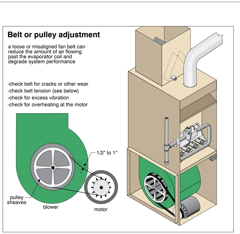 1251
1251Belt or pulley adjustment
· p. 222
The illustration shows a cutaway furnace cabinet with a belt-driven blower and motor in the lower compartment, burners above, and an upper plenum containing a dashed outline of a coil. An enlarged detail shows the belt connecting the motor pulley to the larger blower pulley. Arrows at the belt span indicate a deflection of 1/2 inch to 1 inch for checking tension. The annotations explain that a loose or misaligned belt can reduce airflow past the evaporator coil and degrade performance, and recommend checking belt wear, tension, vibration, and motor overheating.
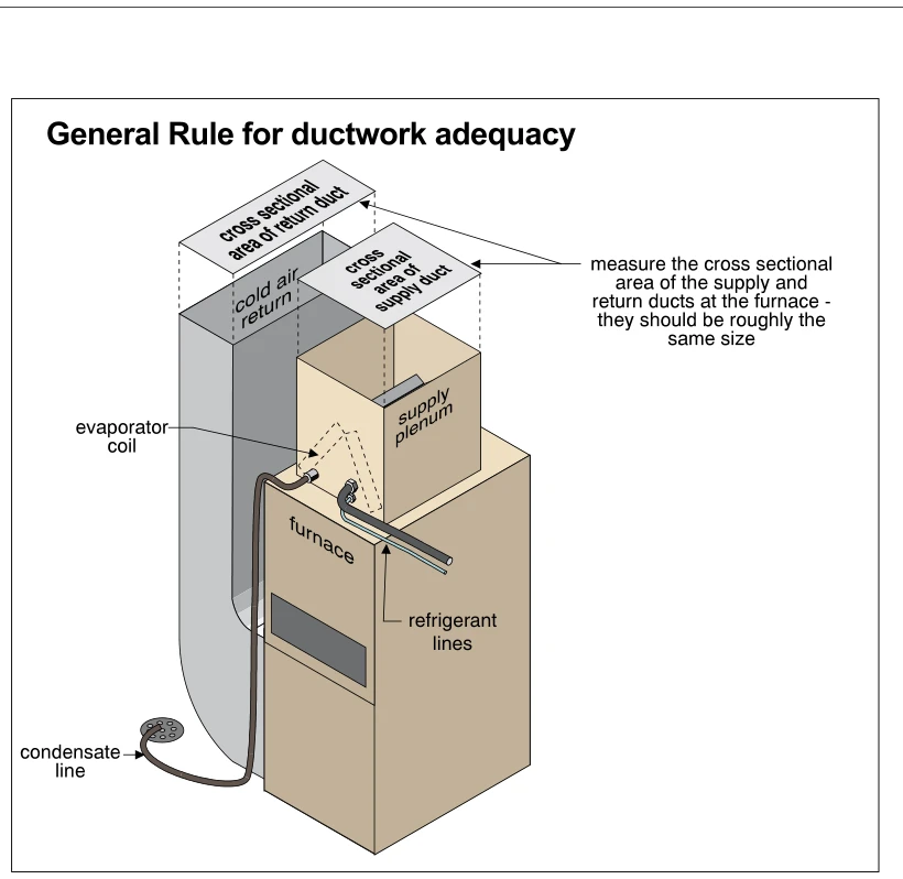 1252
1252General Rule for ductwork adequacy
· p. 222
The illustration shows a furnace with a supply plenum above it and a cold-air return duct descending alongside it. An evaporator coil is outlined inside the supply plenum, with refrigerant lines extending outward and a condensate line running down toward a floor drain. Offset cross-sectional diagrams identify the areas of the supply and return ducts at the furnace. The annotation presents a general adequacy rule that these cross-sectional areas should be roughly the same size.
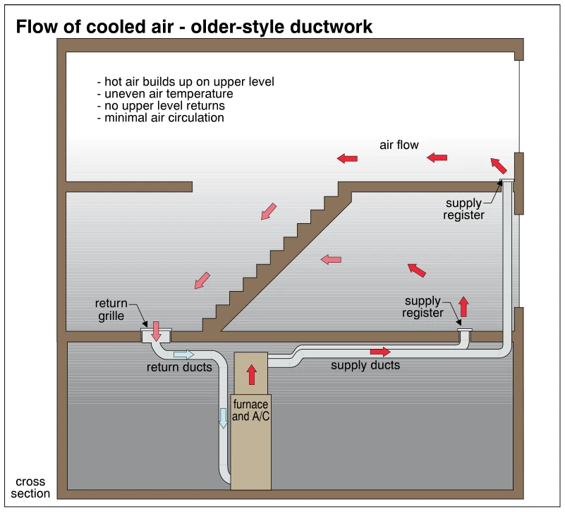 1253
1253Flow of cooled air - older-style ductwork
· p. 222
A house cross section shows a basement furnace and air-conditioning unit connected to supply and return ductwork. Supply ducts feed floor-level registers on the lower and upper occupied levels, while a single return grille is shown at floor level on the lower level. Arrows trace air from the supply registers across the rooms and down the open stairwell toward the return grille, then through the return duct to the equipment. The annotations identify hot air buildup upstairs, uneven temperatures, absent upper-level returns, and minimal air circulation as shortcomings of this older-style duct arrangement.
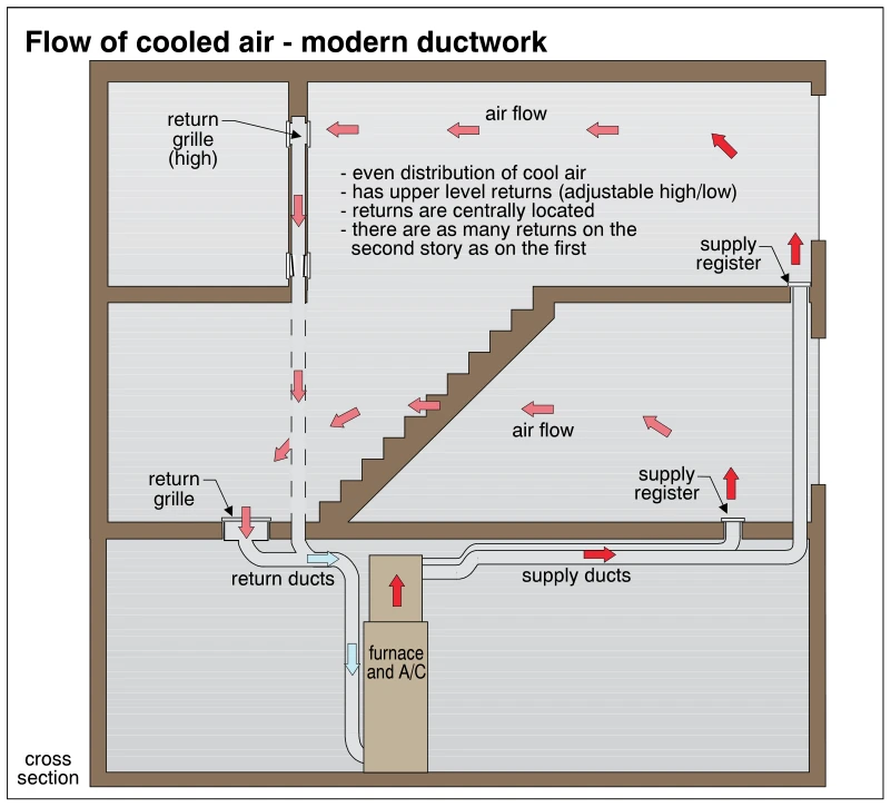 1254
1254Flow of cooled air - modern ductwork
· p. 222
A cross section of a two-story house with a basement shows cooled-air circulation through a forced-air duct system. A basement furnace and A/C unit feeds supply ducts serving registers near the exterior wall on both stories. Arrows show air moving upward from the supply registers, across the rooms, and toward centrally located return grilles. Return ducts carry air back to the equipment, with a high return grille illustrated on the upper story and a low return grille on the first story. The annotations emphasize even cooling, adjustable high/low upper-level returns, centrally located returns, and equal numbers of returns on the two stories.
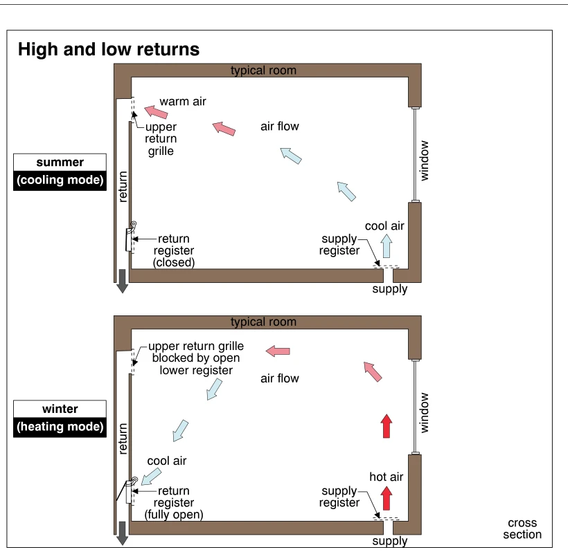 1255
1255High and low returns
· p. 223
Two room cross sections illustrate seasonal operation of high and low return-air openings connected to a common return duct. In summer cooling mode, the lower return register is closed, and warm room air enters the upper return grille while cool air enters through a floor supply register near the window. In winter heating mode, the lower return register is fully open, blocking the path to the upper return grille and drawing cooler air from near floor level. Arrows show heated supply air rising beside the window and circulating across the room before descending toward the low return.
 1256
1256Testing cold air returns
· p. 223
Two panels demonstrate testing airflow at a cold air return grille with a tissue. Panel A shows a hand holding a tissue next to the grille. Panel B uses an arrow to indicate that suction should pull the tissue toward the return. The annotation identifies obstructed ductwork or dirty filters or a dirty coil as possible causes if there is insufficient suction; these conditions are not directly illustrated.
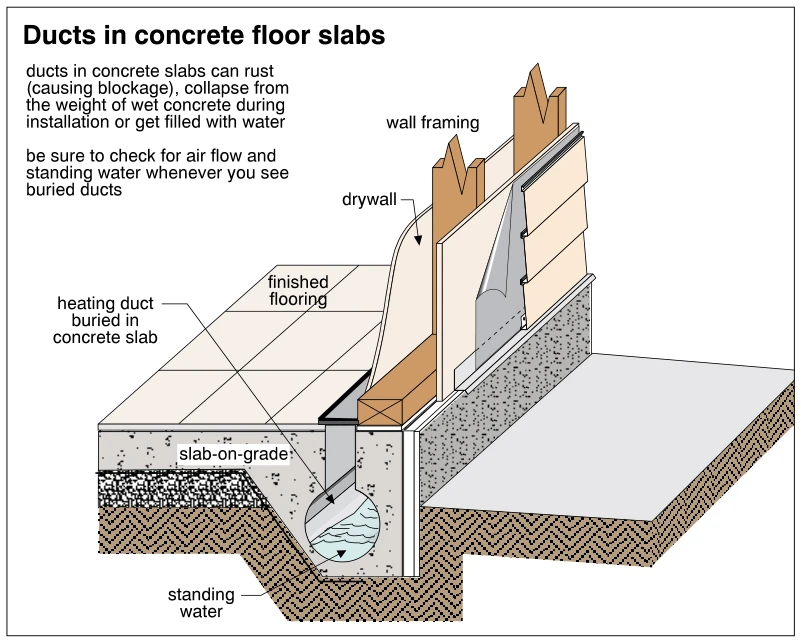 1257
1257Ducts in concrete floor slabs
· p. 223
A cutaway of a slab-on-grade floor and framed exterior wall shows a round heating duct buried in the concrete near the slab edge. A rectangular duct connection rises toward the finished floor beside the wall. Standing water is depicted inside the buried duct. The annotations warn that embedded ducts can rust and become blocked, collapse under wet concrete during installation, or fill with water, and recommend checking airflow and standing water.
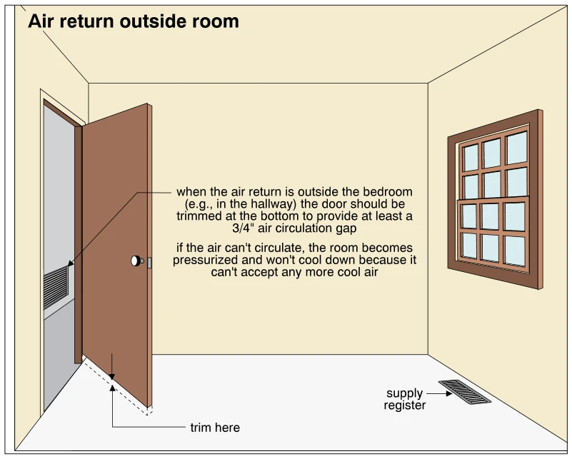 1258
1258Air return outside room
· p. 223
The illustration shows a bedroom with a floor supply register and a return-air grille outside the room, visible through the open doorway. Arrows and a dashed line at the bottom of the door indicate where to trim the door to create an air circulation gap. The annotation calls for at least a 3/4-inch gap when the return is outside the bedroom, such as in a hallway. It explains that an inadequate return-air path can pressurize the room and prevent effective cooling by restricting additional cool supply air.
Air Conditioning ·Thermostatsp. 224
 1259
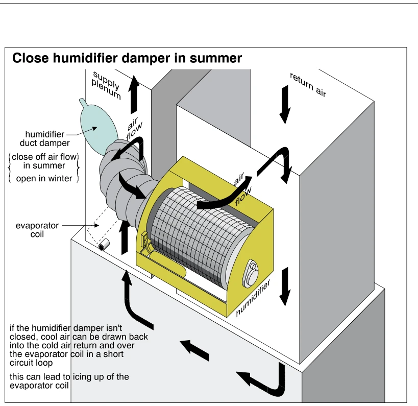
1259Close humidifier damper in summer
· p. 224
The illustration shows a drum-type bypass humidifier connected between the supply plenum and return-air duct, with an evaporator coil indicated below the supply plenum. Arrows trace airflow through the humidifier bypass and back through the return duct, creating a short-circuit loop when the humidifier damper remains open. The annotations warn that this recirculation of cool air can cause evaporator coil icing. The recommended seasonal practice is to close the humidifier duct damper in summer and open it in winter.
 1260
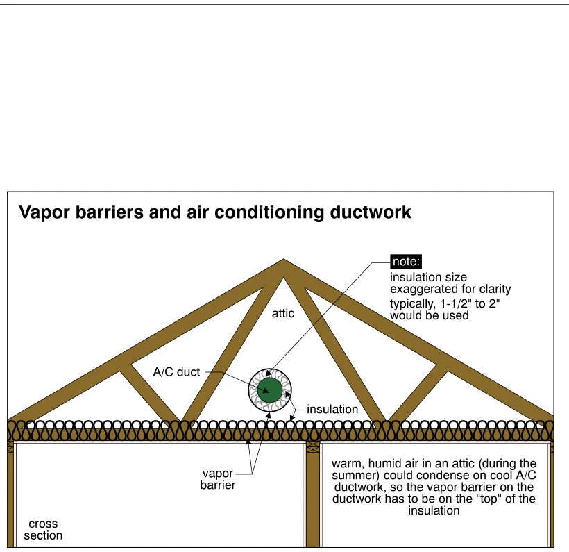
1260Vapor barriers and air conditioning ductwork
· p. 224
A cross section shows an insulated air-conditioning duct in an attic framed with sloping roof members above an insulated ceiling. The round duct is surrounded by insulation, with a vapor barrier on the outside of the duct insulation. The vapor-barrier callout also points to a layer beneath the ceiling insulation. An annotation explains that warm, humid attic air can condense on cool ductwork, requiring the duct vapor barrier to be outside the insulation. A note states that the illustrated duct insulation thickness is exaggerated for clarity and that typically 1-1/2 to 2 inches would be used.
 1260.5
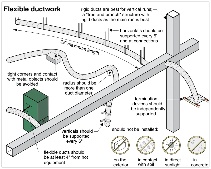
Flexible ductwork
· p. 224
The illustration shows flexible duct branches connected to a rectangular rigid duct distribution system, with rigid ducts recommended for main runs and vertical risers. Horizontal flexible ducts are shown suspended with supports, while a vertical flexible branch has closely spaced support straps. Annotations specify maximum length, support spacing, bend radius, clearance from hot equipment, and independent support for termination devices. A flexible duct crossing a metal object illustrates contact and tight bends to avoid. Prohibition symbols identify exterior installation, soil contact, direct sunlight, and embedment in concrete as unsuitable conditions.
 1261
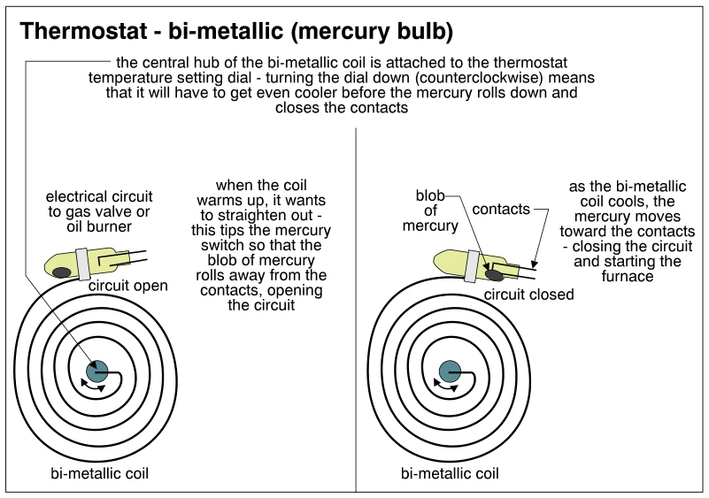
1261Thermostat - bi-metallic (mercury bulb)
· p. 224
Two side-by-side diagrams show the operation of a bi-metallic coil thermostat with a mercury bulb switch. On the left, warming the coil tips the bulb so mercury moves away from the electrical contacts, opening the circuit to the gas valve or oil burner. On the right, cooling the coil tips the bulb toward the contacts, allowing mercury to close the circuit and start the furnace. The central hub connects to the temperature setting dial; turning the dial down counterclockwise requires a lower temperature before the contacts close. Both diagrams illustrate normal operating states rather than defects.
Air Conditioning ·Evaporative Coolersp. 225
 1262
1262Thermostat - bi-metallic (snap-action)
· p. 225
Two side-by-side diagrams show the open and closed states of a snap-action bi-metallic thermostat. On the left, warming causes the spiral coil to straighten, moving its attached magnet away from the contact switch and leaving the burner control circuit open. On the right, cooling moves the magnet toward the switch, pulling up the bottom armature to close the circuit and start the furnace. The central coil hub connects to the temperature setting dial; the annotation explains that turning the dial counterclockwise lowers the temperature required to activate the circuit.
 1263
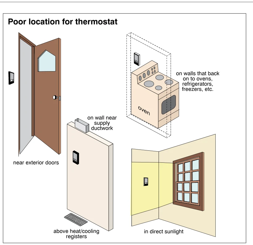
1263Poor location for thermostat
· p. 225
The illustration shows several poor locations for a wall-mounted thermostat. One thermostat is beside an open exterior door, while another is on a wall near supply ductwork and above a floor heating/cooling register. A separate example places the thermostat on a wall backing onto an oven, with an annotation also identifying refrigerators and freezers as problematic adjacent appliances. The final example shows a thermostat exposed to direct sunlight entering through a window. These placements expose the thermostat to localized temperature influences rather than representative room conditions.
 1264
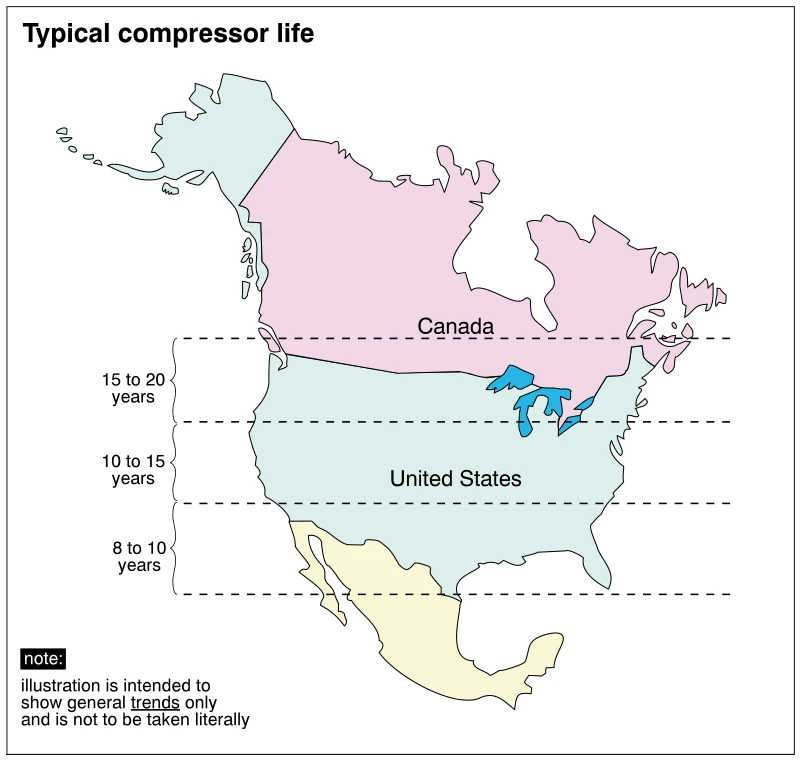
1264Typical compressor life
· p. 225
The illustration shows a map of North America with dashed horizontal lines dividing regions into broad compressor-life bands. Brackets indicate typical life of 15 to 20 years in the northern band, 10 to 15 years in the middle band, and 8 to 10 years in the southern band. Canada and the United States are labeled, and the map conveys a general trend of shorter air-conditioning compressor life farther south. A note explicitly states that these are general trends and are not to be taken literally. No compressor assembly or physical defect is depicted.
 1265
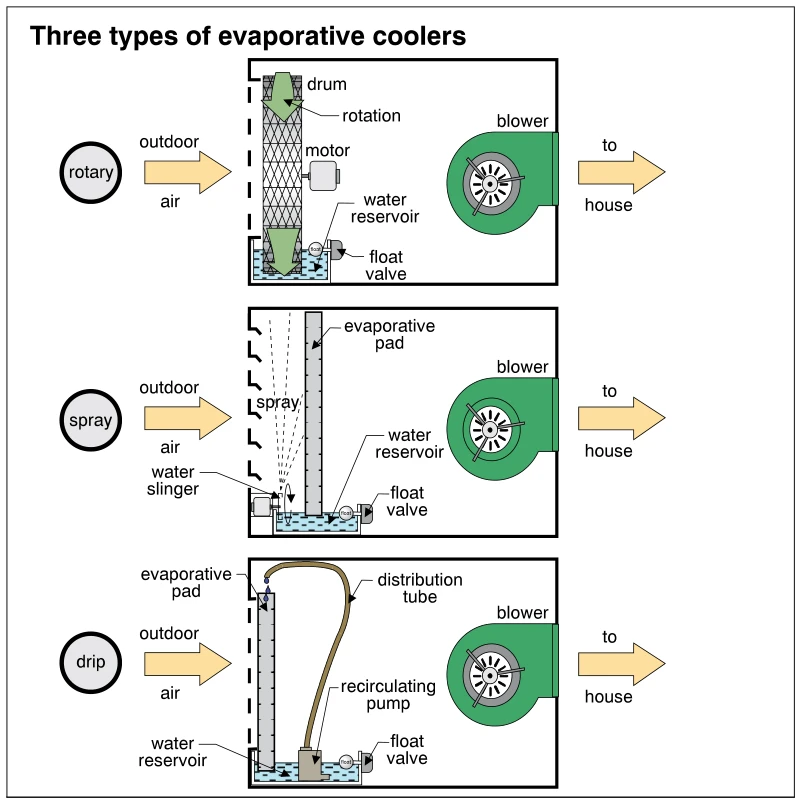
1265Three types of evaporative coolers
· p. 225
Three schematic sections depict rotary, spray, and drip evaporative coolers, each drawing outdoor air through a wetted drum or pad and delivering air to the house with a blower. The rotary unit has a motor-driven drum whose lower portion passes through a water reservoir. The spray unit uses a water slinger to spray water onto an evaporative pad. The drip unit uses a recirculating pump and distribution tube to deliver reservoir water to the top of an evaporative pad. Each reservoir has a float valve, and no defects are depicted.
Heat Pumps ·Heat Pumps in Theoryp. 226
 1265.3
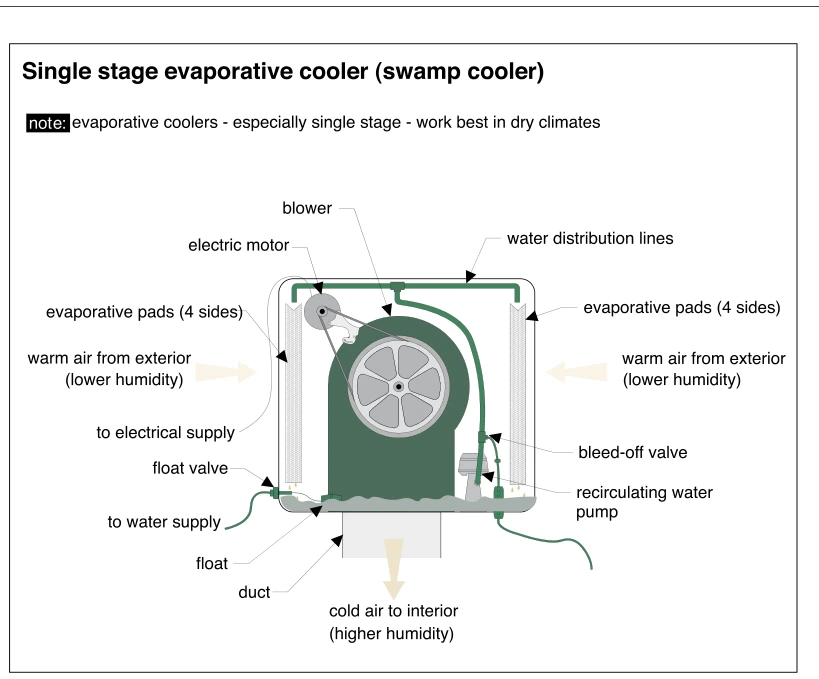
Single stage evaporative cooler (swamp cooler)
· p. 226
The illustration shows a cutaway schematic of a single-stage evaporative cooler, also called a swamp cooler. Warm, lower-humidity exterior air enters through evaporative pads on four sides, and an electric-motor-driven blower delivers colder, higher-humidity air through a bottom outlet duct to the interior. A recirculating water pump supplies water distribution lines above the pads from the bottom reservoir. A float and float valve control the incoming water supply, and a bleed-off valve is identified on the water circuit. The note states that evaporative coolers, especially single-stage units, work best in dry climates; no defects are depicted.
 1265.6
Two stage evaporative cooler (swamp cooler)
· p. 226
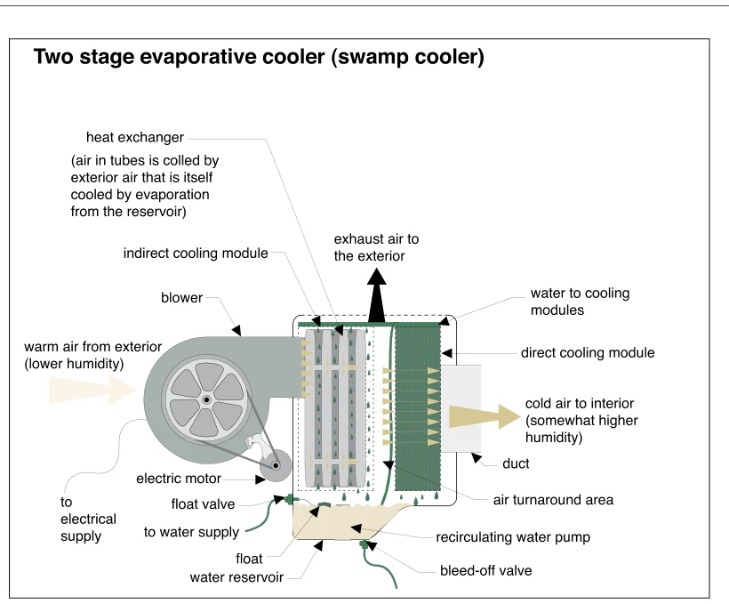
The cutaway schematic shows a two-stage evaporative cooler with a motor-driven blower drawing warm, lower-humidity outdoor air into an indirect cooling module. Air in the heat exchanger tubes is cooled by a separate evaporatively cooled air stream, with exhaust directed outdoors. The supply air then passes through a direct cooling module and leaves through a duct as colder air with somewhat higher humidity. A reservoir below the modules supplies recirculated water, while a float and float valve control makeup water from the water supply. A bleed-off valve is shown at the bottom of the water system.
 1266
1266Whole house fan
· p. 226
A house cross section shows a whole-house fan mounted in the ceiling below the attic, with louvers that open when the fan operates. Arrows show air drawn upward from the living space into the attic and discharged through roof and soffit vents. A wood-burning fireplace and a basement gas furnace are shown with separate vertical exhaust paths. Red arrows at these appliances illustrate the potential for backdrafting when the fan operates. The annotation advises opening several windows to prevent backdrafting and testing whole-house fans only in summer.
 1267
1267Whole house fan - inadequate attic venting
· p. 226
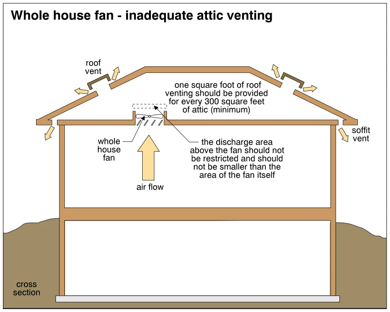
A house cross section shows a ceiling-mounted whole-house fan discharging indoor air upward into the attic. Arrows show air leaving the attic through roof and soffit vents. An annotation specifies a minimum of one square foot of roof venting for every 300 square feet of attic. Another annotation states that the discharge area above the fan must be unrestricted and at least as large as the fan itself. The illustration addresses inadequate attic venting by identifying the required exhaust provisions rather than showing a clearly blocked vent.
 1268
1268Heat pump principles
· p. 226
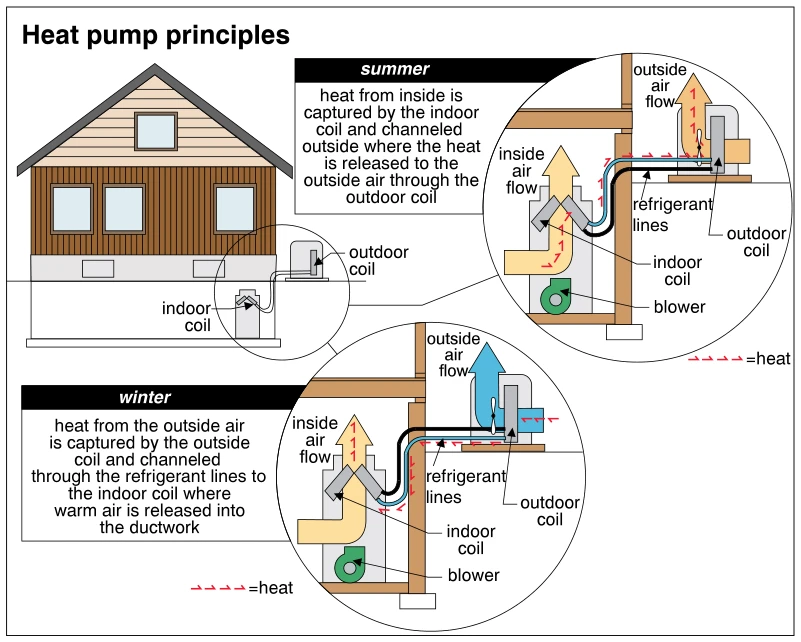
The illustration shows a house with indoor and outdoor heat pump coils connected by refrigerant lines, with enlarged diagrams of summer and winter operation. In summer, heat is captured at the indoor coil and transferred through the refrigerant circuit to the outdoor coil, where it is released to outside air. In winter, heat is captured from outside air at the outdoor coil and transferred to the indoor coil to warm air delivered into the ductwork. Each enlarged view shows an indoor blower, airflow across both coils, and red dashed arrows indicating heat transfer.
 1269
1269Heat pump evaporator coil - grabbing heat from the outside air
· p. 226
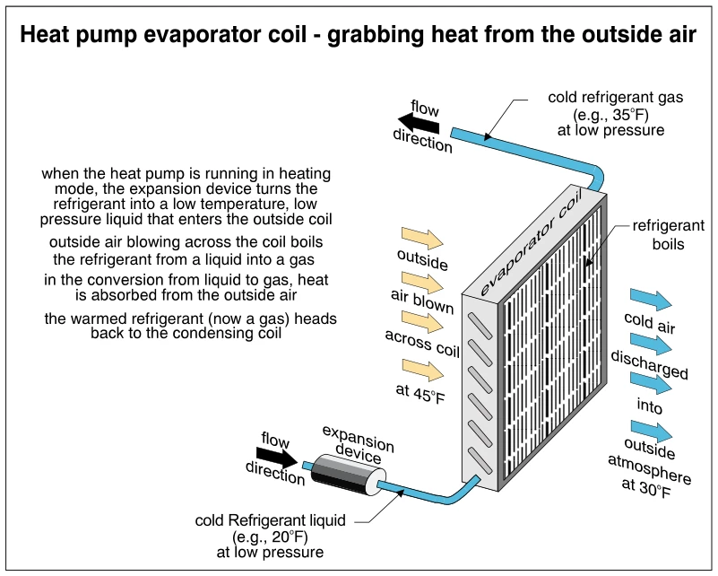
The diagram depicts an outdoor heat pump evaporator coil operating in heating mode. Low-pressure liquid refrigerant, illustrated at 20°F, passes through an expansion device and enters the bottom of the coil. Outside air at 45°F flows across the coil, transferring heat to the refrigerant and causing it to boil from liquid to gas. Low-pressure refrigerant gas, illustrated at 35°F, leaves the top of the coil, while the cooled air is discharged outside at 30°F. Arrows indicate refrigerant and airflow directions; no defects are depicted.
 1270
1270Heat pump condenser coil - giving off warm air to the inside
· p. 227
The diagram shows a heat pump's indoor condenser coil connected to a compressor during heating operation. Hot, high-pressure refrigerant gas enters the coil at an example temperature of 160°F and leaves as warm, high-pressure liquid at 110°F. Blue arrows indicate indoor air entering the coil at 70°F, while red arrows indicate heated air leaving at 90°F for distribution through ductwork. The annotations explain that refrigerant condensation releases heat into the supply air.
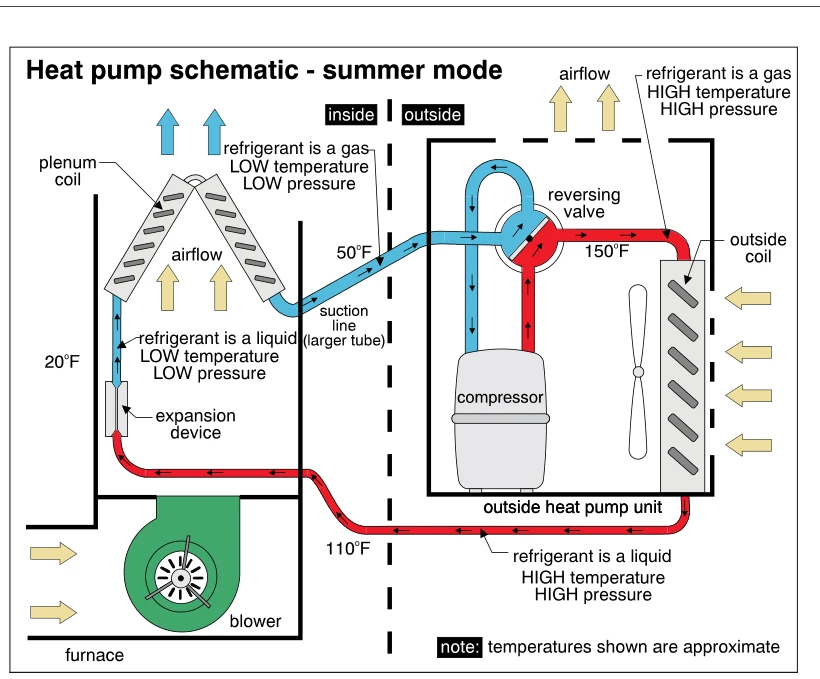 1271
1271Heat pump schematic - summer mode
· p. 227
This schematic shows a heat pump operating in summer cooling mode, with an indoor furnace blower and plenum coil connected to an outdoor compressor, reversing valve, and coil. Arrows show indoor air moving upward through the plenum coil and outdoor air moving across the outside coil. Low-pressure refrigerant passes through the indoor coil and returns as low-temperature gas through the larger suction line and reversing valve to the compressor. High-temperature, high-pressure gas flows from the compressor through the reversing valve to the outdoor coil, with high-pressure liquid returning to the indoor expansion device. Blue and red piping distinguish the low- and high-temperature portions of the circuit, and the illustrated temperatures are explicitly identified as approximate.
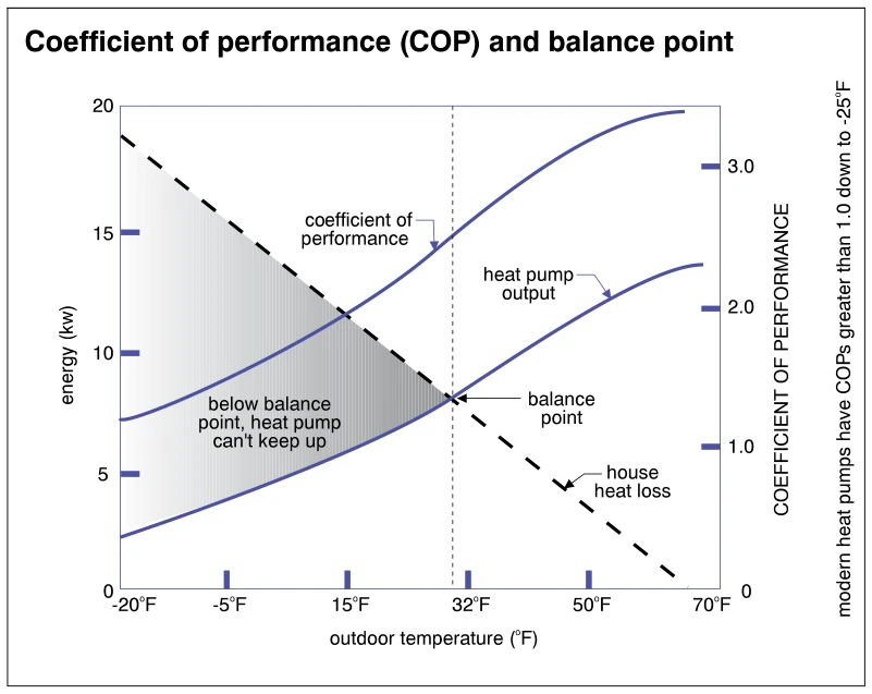 1272
1272Coefficient of performance (COP) and balance point
· p. 227
The illustration graphs heat pump output, coefficient of performance (COP), and house heat loss against outdoor temperature. Two solid curves show heat pump output and COP increasing as outdoor temperature rises, while a descending dashed line represents decreasing house heat loss. The balance point is marked where heat pump output equals house heat loss, slightly below 32°F, with a vertical dashed reference line. A shaded region below that outdoor temperature identifies the heating shortfall where the heat pump cannot keep up with house heat loss. A side annotation states that modern heat pumps have COPs greater than 1.0 down to -25°F.
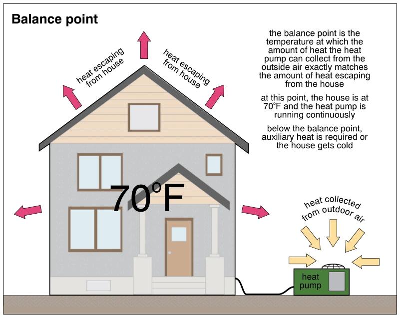 1273
1273Balance point
· p. 227
The illustration shows a house maintained at 70°F with an outdoor heat pump connected to it. Pink arrows pointing away from the roof and walls represent heat escaping from the house, while yellow arrows pointing toward the heat pump represent heat collected from outdoor air. The annotations define the balance point as the outdoor temperature at which heat collected by the heat pump exactly matches the house's heat loss. At this point the heat pump runs continuously; below this temperature, auxiliary heat is needed to prevent the house from cooling.
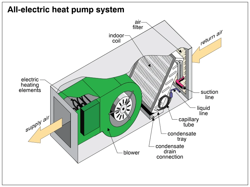 1274
1274All-electric heat pump system
· p. 227
A cutaway view shows the indoor air-handling assembly of an all-electric heat pump system. Return air enters at the right through an air filter and passes through the indoor coil toward the blower. The blower moves air past electric heating elements and out the supply-air opening at the left. Suction and liquid refrigerant lines and a capillary tube are identified beside the coil. A condensate tray beneath the coil leads to a condensate drain connection; no defects are depicted.
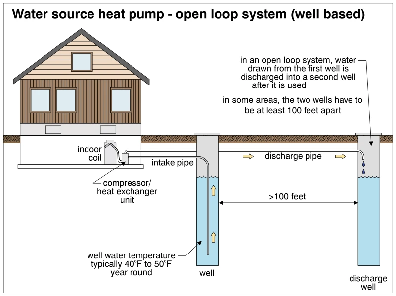 1275
1275Water source heat pump - open loop system (well based)
· p. 227
The illustration shows a well-based, open-loop water-source heat pump serving a house. Groundwater travels upward from a supply well through an intake pipe to a compressor/heat exchanger unit connected to an indoor coil. After use, water flows through a discharge pipe into a separate discharge well, with arrows indicating flow direction. A dimension marks the wells as more than 100 feet apart, and an annotation notes that at least 100 feet of separation is required in some areas. The supply well annotation gives a typical year-round water temperature of 40°F to 50°F.
Heat Pumps ·Heat Pumps in Practicep. 228
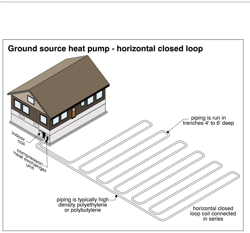 1276
1276Ground source heat pump - horizontal closed loop
· p. 228
The illustration shows a house connected to a horizontal closed-loop ground-source heat pump system. A long serpentine piping circuit extends beside the house, with successive horizontal runs connected in series by return bends. An annotation specifies that the piping is installed in trenches 4 to 6 feet deep, although the ground is omitted to expose the layout. The piping is identified as typically high-density polyethylene or polybutylene, and the house-side equipment is labeled as an indoor coil and compressor/heat exchanger unit. No defects or improper installation conditions are indicated.
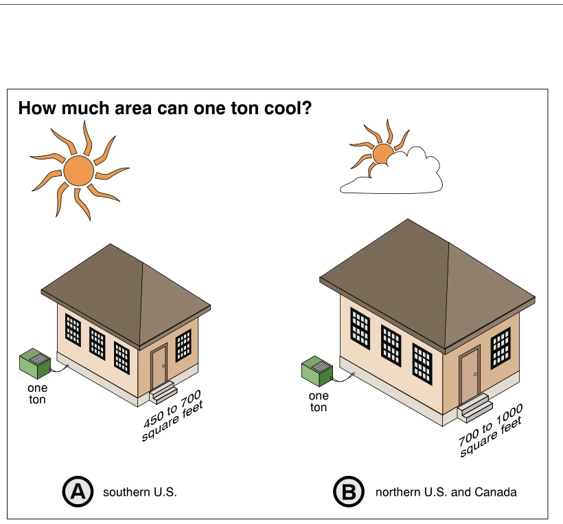 1277
1277How much area can one ton cool?
· p. 228
The illustration compares the floor area served by one ton of cooling capacity in two geographic regions. Panel A shows a smaller house beneath a sun, labeled southern U.S., with a one-ton outdoor unit and an area of 450 to 700 square feet. Panel B shows a larger house beneath a partly cloudy sun, labeled northern U.S. and Canada, with a one-ton outdoor unit and an area of 700 to 1000 square feet. Both outdoor units are connected to their respective houses, illustrating regional differences in cooling capacity per unit of floor area rather than an installation defect.
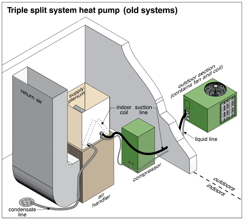 1278
1278Triple split system heat pump (old systems)
· p. 228
The illustration depicts an older triple-split heat pump with an indoor air handler and coil, a separate indoor compressor, and an outdoor fan-and-coil section. The indoor coil sits in the supply plenum above the air handler, beside the return-air duct. Refrigerant suction and liquid lines connect the separated equipment, passing through the exterior wall to the outdoor section. A condensate line runs from the indoor coil enclosure to a floor drain. No defects or improper installation practices are identified.
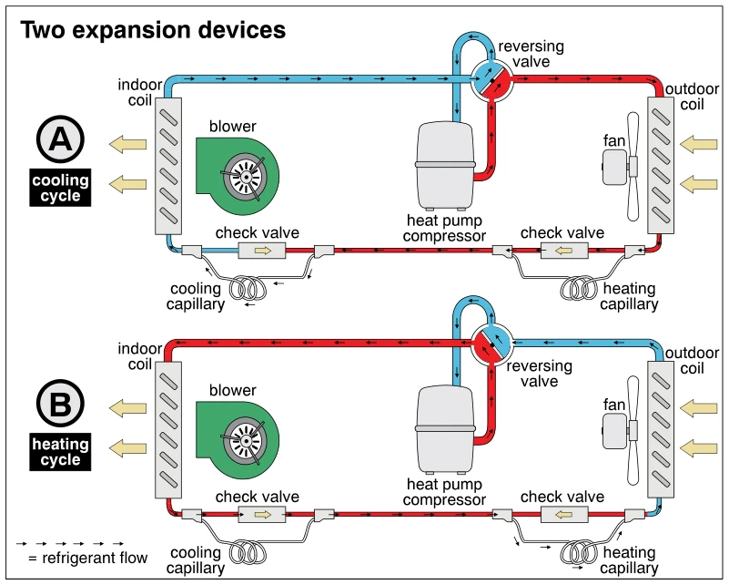 1279
1279Two expansion devices
· p. 228
Two schematic diagrams compare refrigerant flow in a heat pump during the cooling cycle (A) and heating cycle (B). Each shows an indoor coil and blower, an outdoor coil and fan, a compressor, and a reversing valve connected by red and blue refrigerant lines. Separate cooling and heating capillary expansion devices are each piped in parallel with a check valve. Flow arrows show refrigerant passing through the cooling capillary during cooling and through the heating capillary during heating, with the other capillary bypassed through its associated check valve. The reversing valve changes the flow path between operating modes.
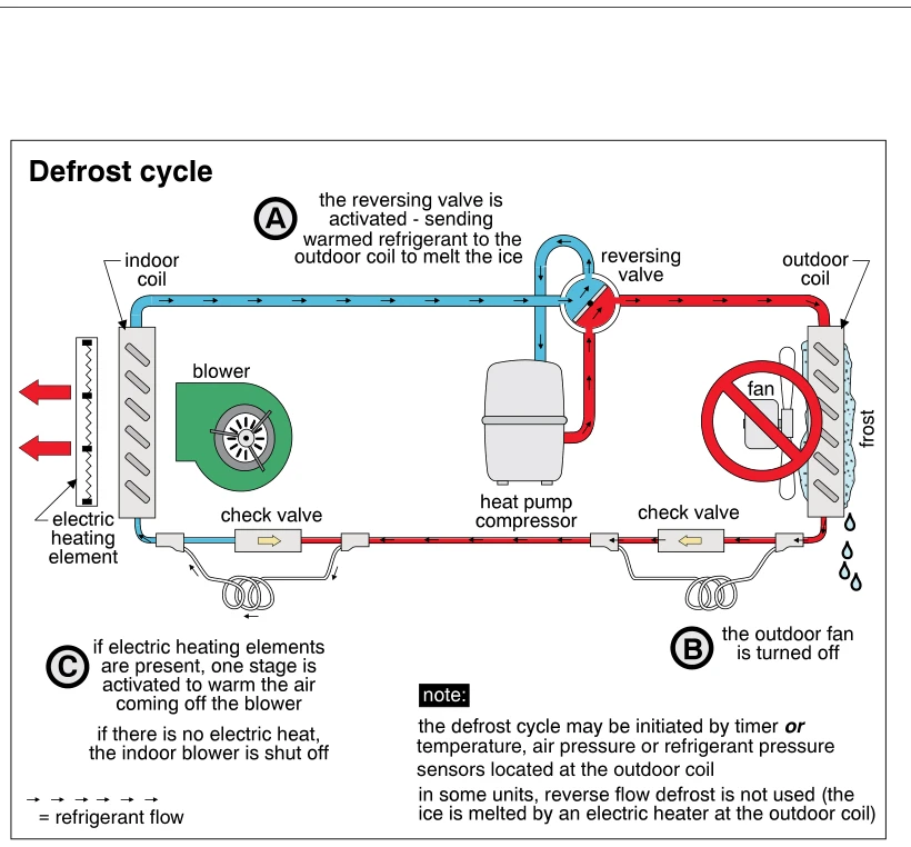 1280
1280Defrost cycle
· p. 229
The schematic shows a heat pump operating in its defrost cycle, with red and blue refrigerant piping connecting the compressor, reversing valve, indoor coil, outdoor coil, and check valves. The reversing valve directs warmed refrigerant to the frost-covered outdoor coil to melt ice, illustrated by water droplets beneath the coil. A prohibition symbol over the outdoor fan indicates that it is turned off during defrost. At the indoor coil, an electric heating element warms air leaving the blower when electric heat is available; otherwise, the annotation specifies that the indoor blower is shut off. Notes identify timer- or sensor-initiated defrost and an alternative arrangement using an electric heater at the outdoor coil.
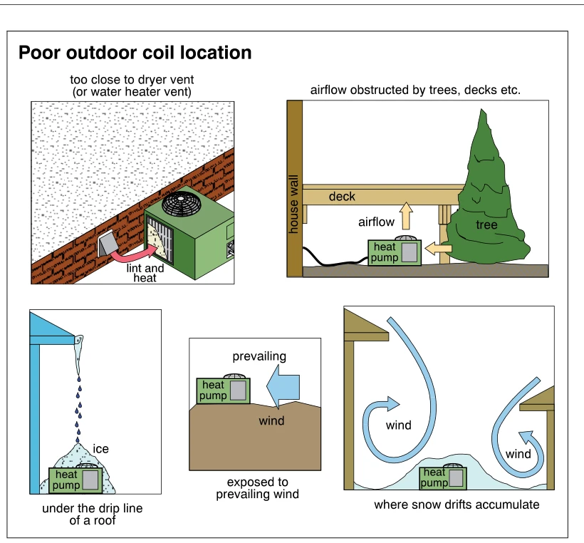 1281
1281Poor outdoor coil location
· p. 229
Five diagrams illustrate poor locations for a heat pump outdoor coil unit. One places the unit beside a dryer or water heater vent, with lint and heat directed toward the coil. Another shows airflow obstructed by an overhead deck and an adjacent tree. A unit beneath a roof drip line is surrounded by ice, while another is exposed to prevailing wind. The final diagram shows wind circulating between buildings and snow drifting around the outdoor unit.
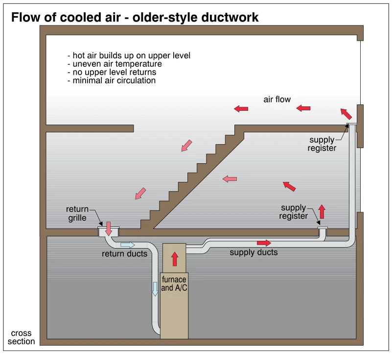 1282
1282Flow of cooled air - older-style ductwork
· p. 229
A house cross section shows a basement furnace and air-conditioning unit connected to supply registers on two occupied levels and a single lower-level return grille. Supply ducts run beneath the lower floor and rise along the exterior wall to the upper-level register. Arrows show cooled air entering both levels, with upper-level air moving toward the stair opening and descending toward the lower-level return. The annotations identify the absence of upper-level returns, hot-air buildup upstairs, uneven temperatures, and minimal air circulation as problems with this older-style duct arrangement.
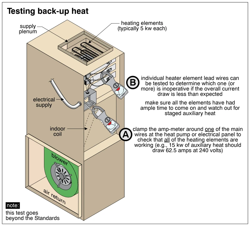 1283
1283Testing back-up heat
· p. 229
A cutaway indoor heat-pump air handler shows a bottom air return and blower, an indoor coil above, and electric back-up heating elements in the supply plenum. Two clamp-on ammeters illustrate measuring current around a main supply wire and an individual heater element lead wire. The annotations explain checking total current draw to verify operation of all elements, then testing individual leads if the total draw is lower than expected. They also caution that elements need time to energize and that auxiliary heat may be staged. A note states that this test goes beyond the Standards.
 1284
1284Water source heat pump - open loop system (well based)
· p. 230
The illustration shows a well-based, open-loop water-source heat pump serving a house. Arrows show groundwater rising from a supply well through an intake pipe to the compressor/heat exchanger unit, which is connected to an indoor coil. Used water travels through a discharge pipe into a separate discharge well rather than returning through a closed loop. The drawing indicates a well separation greater than 100 feet and notes that at least 100 feet is required in some areas. Supply well water is labeled as typically 40°F to 50°F year round.
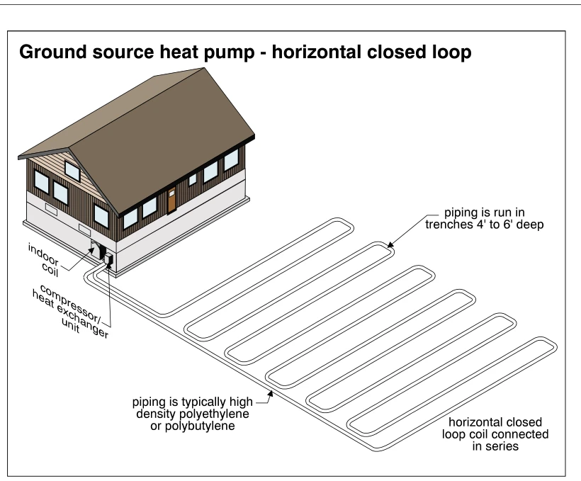 1285
1285Ground source heat pump - horizontal closed loop
· p. 230
The illustration shows a house connected to a horizontal closed-loop ground-source heat pump system. An indoor coil and a compressor/heat exchanger unit are identified at the house. The ground-loop piping forms a series of long parallel runs joined by return bends and connected in series. Annotations specify installation in trenches 4 to 6 feet deep and identify the piping as typically high-density polyethylene or polybutylene. No defects or improper installation practices are depicted.
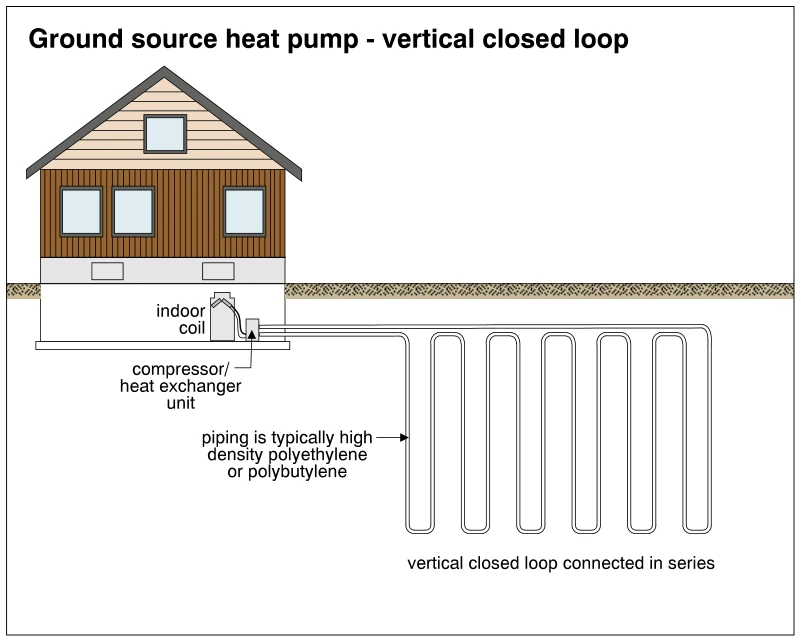 1286
1286Ground source heat pump - vertical closed loop
· p. 230
The illustration shows a house connected to a ground-source heat pump with a buried vertical closed-loop piping system. An indoor coil and a compressor/heat exchanger unit are shown at the lower level of the house. Piping extends horizontally underground and forms a series of deep vertical U-shaped loops before returning to the equipment. The ground loops are labeled as connected in series, and the piping is identified as typically high density polyethylene or polybutylene. No defects or improper installation practices are indicated.
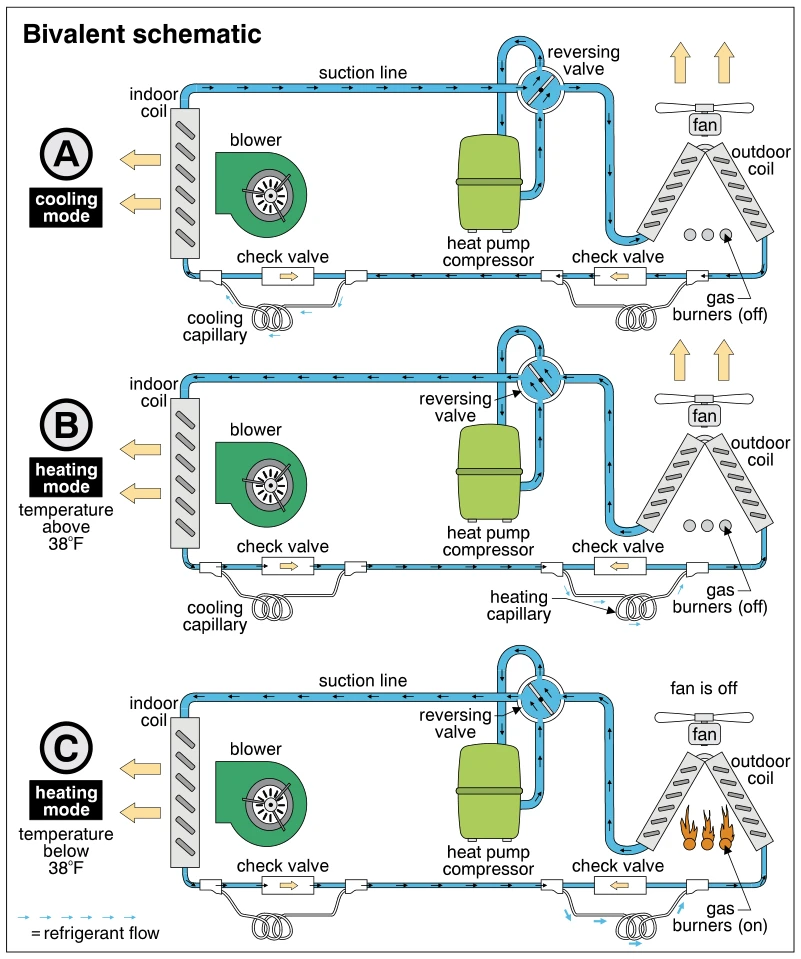 1287
1287Bivalent schematic
· p. 230
The schematic shows three operating modes of a bivalent heat pump, with refrigerant flow arrows connecting an indoor coil, compressor, reversing valve, and outdoor coil. Panel A depicts cooling operation with the gas burners off and heat discharged at the outdoor coil. Panel B depicts heating above 38°F, with reversed refrigerant flow, a heating capillary, and the gas burners off. Panel C depicts heating below 38°F, with gas burners firing beneath the outdoor coil and the outdoor fan off. Check valves and capillary bypass paths control refrigerant routing, while the indoor blower moves air across the indoor coil.