
09Interior
98 illustrations · printed pages 351-374
Floorsp. 352
 2000
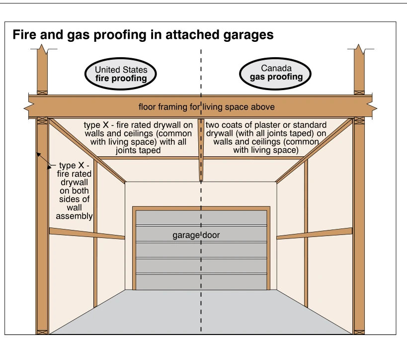
2000Fire and gas proofing in attached garages
· p. 352
The illustration shows an attached garage beneath living space, with a dashed centerline comparing United States fire proofing and Canadian gas proofing. Floor framing spans above the garage ceiling, and framed sidewalls flank a sectional garage door. The United States side specifies Type X fire-rated drywall with taped joints on walls and ceilings common with living space, and identifies Type X drywall on both sides of the wall assembly. The Canadian side specifies two coats of plaster or standard drywall with all joints taped on walls and ceilings common with living space.
 2001
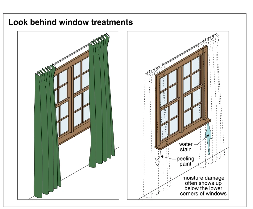
2001Look behind window treatments
· p. 352
Two views show a divided-light window with long curtains covering the wall beneath its lower corners. In the left view, the curtains conceal these areas; in the right view, dashed outlines represent the curtains so the wall damage can be seen. A water stain extends below the right end of the window sill, and peeling paint appears below the left end. The illustration emphasizes looking behind window treatments for moisture damage, particularly below the lower corners of windows.
 2002
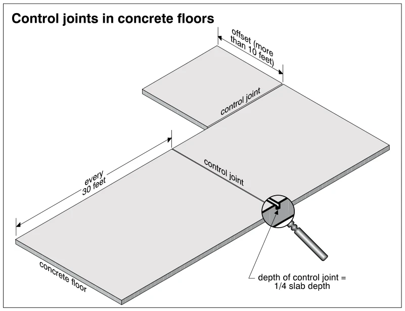
2002Control joints in concrete floors
· p. 352
The illustration shows an offset concrete floor slab divided by control joints. One joint crosses the main slab, with an annotation indicating spacing every 30 feet. Another joint separates an offset portion labeled as more than 10 feet. A magnified edge detail shows a groove extending one-quarter of the slab depth rather than through its full thickness.
 2003
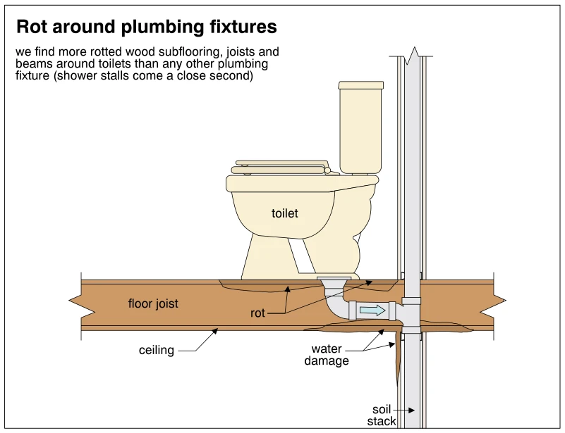
2003Rot around plumbing fixtures
· p. 352
The illustration shows a toilet above a wood floor assembly in a sectional view. The toilet outlet connects through an elbow and horizontal drain branch to a vertical soil stack penetrating the floor and ceiling. Callouts identify rot beneath the toilet and water damage at the ceiling near the stack penetration. The annotation emphasizes that wood subflooring, joists, and beams around toilets are particularly susceptible to rot, with shower stalls also noted as common locations.
 2004
2004Sources of interior water damage
· p. 353
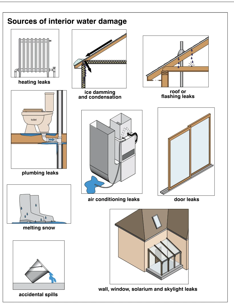
Nine vignettes illustrate potential sources of interior water damage, including damage to floors. A radiator represents heating leaks, while roof sections show ice damming at an eave and water dripping beneath a roof near a pipe penetration. A toilet and drain piping illustrate plumbing leakage, and an air-conditioning assembly above a furnace is shown with water pooling on the floor. Other panels depict a sliding glass door, melting snow on boots, and a tipped bucket spilling water. A house exterior with a glazed solarium and skylight represents leaks through walls, windows, solariums, and skylights.
 2005
2005Concrete floor problems
· p. 353
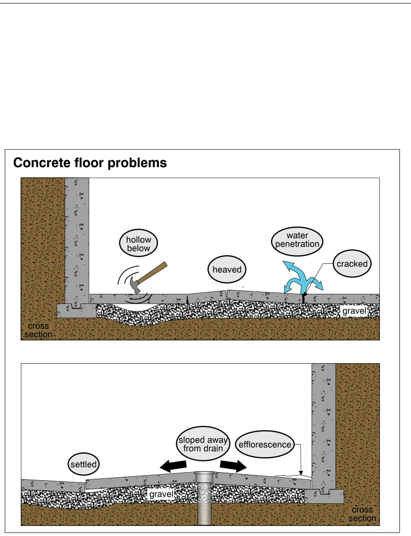
Two cross sections depict concrete floor slabs supported on gravel over soil, adjoining foundation walls and footings. The upper section shows a void beneath the slab, illustrated with a hammer tapping the hollow area, along with heaving and cracking. Blue arrows indicate water penetration through a slab crack. The lower section shows settlement and a floor sloping away from a central floor drain rather than toward it. Efflorescence is identified on the slab surface near the foundation wall.
 2006
2006Hollows
· p. 353
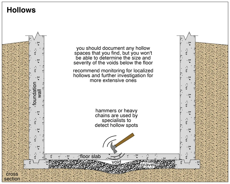
The cross section shows a concrete floor slab between foundation walls supported on footings, with gravel beneath the slab and surrounding soil. A localized depression in the gravel leaves a void beneath the center of the slab. A hammer striking the slab illustrates sounding methods used by specialists to detect hollow spots; the annotation also mentions heavy chains. The notes advise documenting hollows while acknowledging that the size and severity of concealed voids cannot be determined, and recommend monitoring localized hollows and further investigation of more extensive ones.
 2007
2007Causes of rot
· p. 353
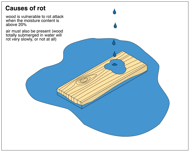
The illustration shows a wood board surrounded by pooled water, with droplets falling onto a puddle on its upper surface. The annotations explain that wood becomes vulnerable to rot when its moisture content exceeds 20%. Air must also be present for rot to develop; totally submerged wood is described as rotting very slowly or not at all. The drawing illustrates conditions conducive to wood decay rather than showing visible decay damage.
Wallsp. 354
 2008
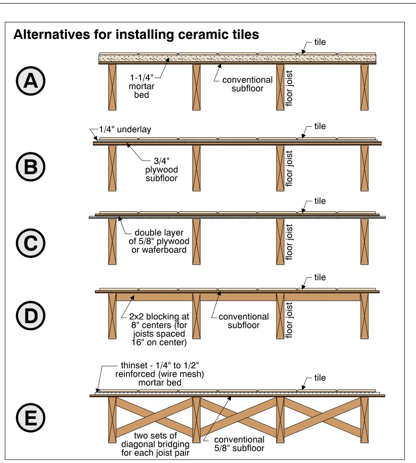
2008Alternatives for installing ceramic tiles
· p. 354
Five sectional diagrams, labeled A through E, show alternative ceramic floor tile assemblies supported by wood floor joists. A uses a 1-1/4-inch mortar bed over a conventional subfloor, while B uses a 1/4-inch underlay over a 3/4-inch plywood subfloor. C shows a double layer of 5/8-inch plywood or waferboard beneath the tiles. D shows a conventional subfloor reinforced with 2x2 blocking at 8-inch centers for joists spaced 16 inches on center. E shows a 1/4- to 1/2-inch wire-mesh-reinforced mortar bed over a conventional 5/8-inch subfloor, with two sets of diagonal bridging for each joist pair. No damage or improper installation is marked.
 2009
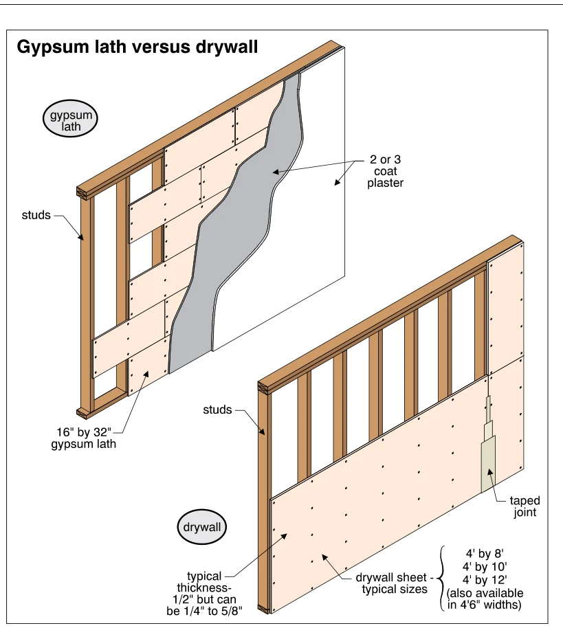
2009Gypsum lath versus drywall
· p. 354
Two cutaway wall assemblies compare gypsum lath with drywall on wood stud framing. The upper assembly shows small 16-inch by 32-inch gypsum lath panels fastened to studs and covered with two or three coats of plaster, with peeled-back layers exposing the construction. The lower assembly shows larger drywall sheets fastened directly to studs, with a taped joint between adjacent sheets. Annotations identify typical drywall sheet sizes and a typical thickness of 1/2 inch, with a range from 1/4 inch to 5/8 inch. No defects are depicted.
 2010
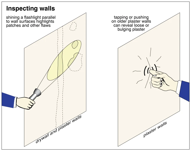
2010Inspecting walls
· p. 354
The illustration shows two methods for inspecting interior wall finishes. On the left, a flashlight held at a shallow angle casts light along a drywall or plaster surface to highlight patches and surface irregularities. On the right, a hand taps or pushes an older plaster wall, with cracks and motion marks drawn around the contact area. The annotation explains that this technique can reveal loose or bulging plaster.
 2011
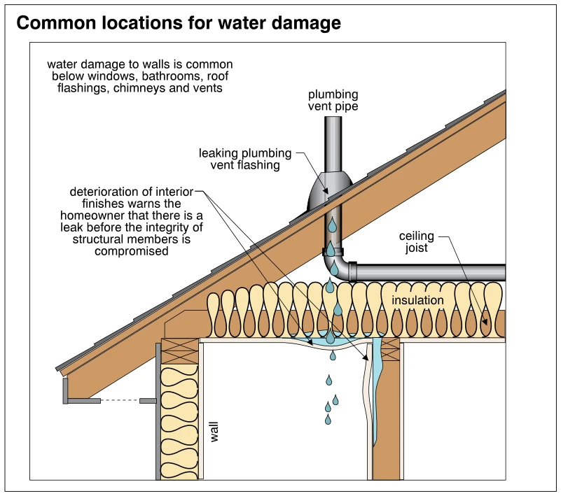
2011Common locations for water damage
· p. 354
A sectional drawing shows a plumbing vent pipe penetrating a sloped roof above an insulated ceiling and walls. Water enters at the leaking vent flashing and runs down beside the pipe into the ceiling assembly. Water collects above a sagging ceiling finish, drips into the room, and travels down behind an interior wall finish. An annotation explains that deterioration of interior finishes can warn of a leak before structural members are compromised. The figure also identifies windows, bathrooms, roof flashings, chimneys, and vents as common locations above water-damaged walls.
 2012
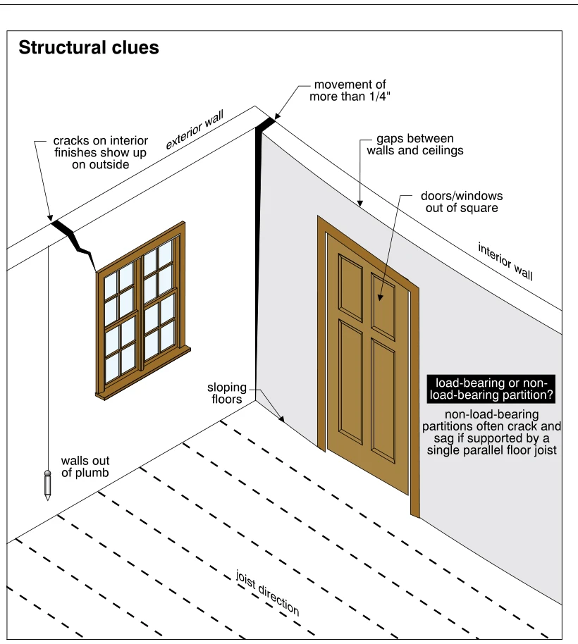
2012Structural clues
· p. 355
A cutaway room corner illustrates visible clues to structural movement in exterior and interior walls. A crack extends toward a window opening, and a dark separation at the wall junction is labeled as movement of more than 1/4 inch. Other annotations identify wall-to-ceiling gaps, out-of-square doors or windows, sloping floors, and walls out of plumb, with a plumb bob shown beside the exterior wall. Dashed lines indicate floor joist direction, parallel to the interior partition. A note warns that non-load-bearing partitions often crack and sag when supported by a single parallel floor joist.
 2013
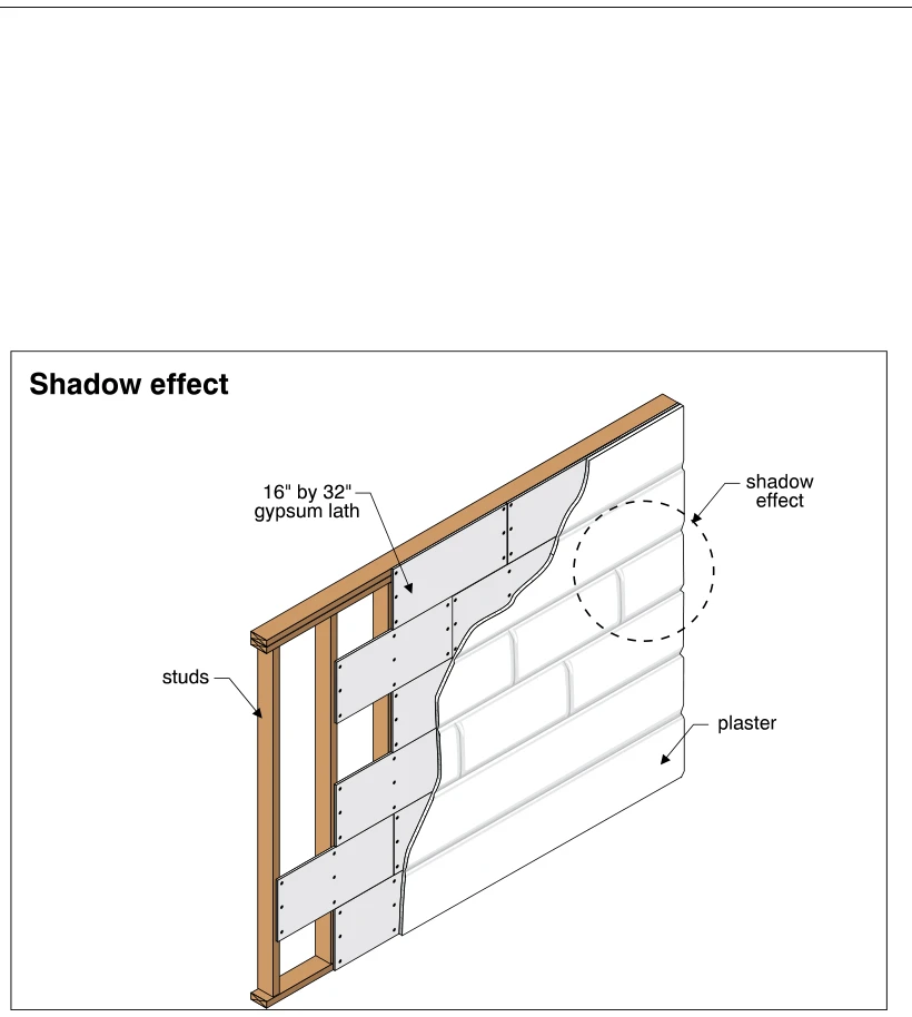
2013Shadow effect
· p. 355
A cutaway interior wall shows wood studs supporting rectangular gypsum lath panels beneath a plaster finish. The lath is installed horizontally with staggered vertical joints and visible fasteners at the framing. On the finished portion, horizontal and vertical shadow lines reveal the pattern of the underlying lath joints. A dashed circle highlights this shadow effect on the plaster surface.
 2014
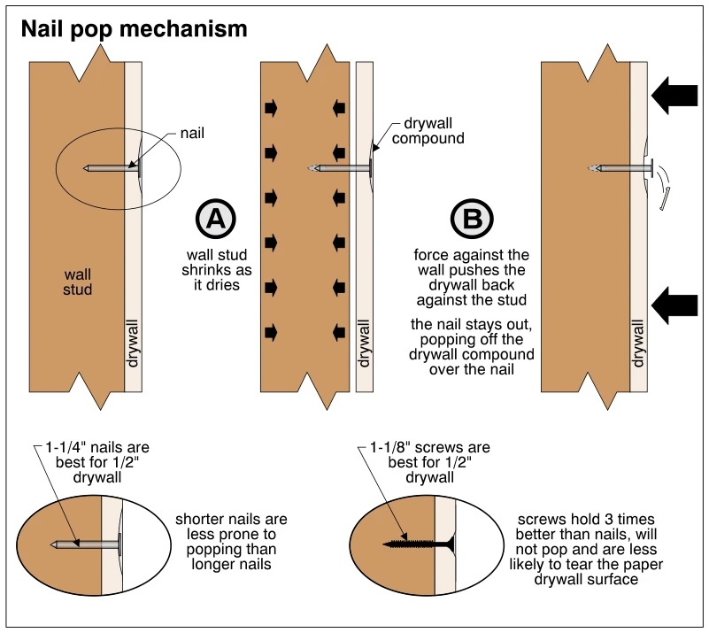
2014Nail pop mechanism
· p. 355
Sequential cross-sections show the mechanism of a nail pop in drywall attached to a wood wall stud. As the stud dries and shrinks, a gap develops between the stud and the drywall. Force against the wall then pushes the drywall back against the stud while the nail remains projecting, dislodging the drywall compound over its head. Enlarged details below compare nail and screw attachment, recommending shorter nails and presenting screws as more resistant to popping and paper-surface damage.
 2015
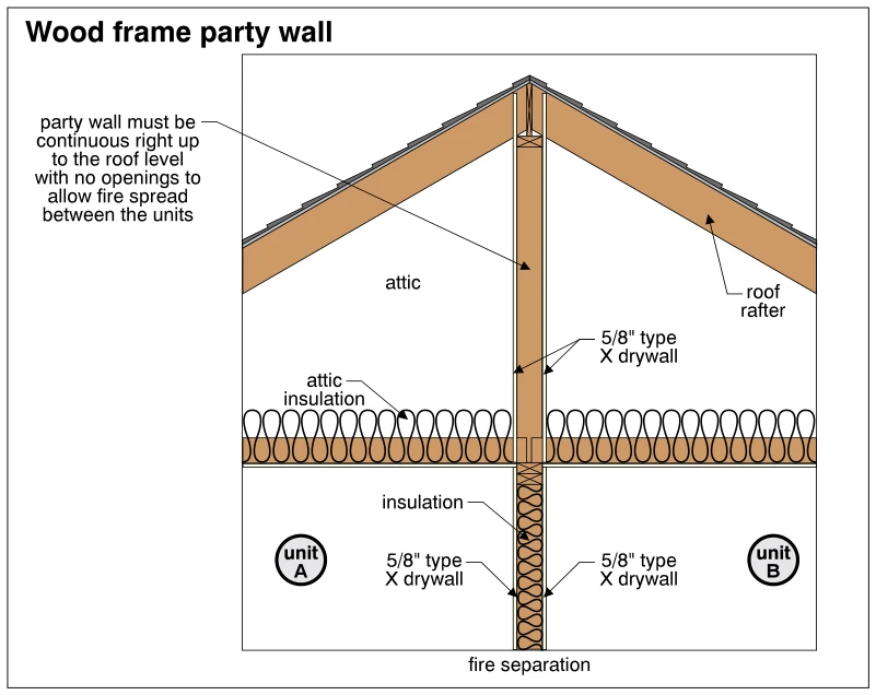
2015Wood frame party wall
· p. 355
The section shows a wood-frame party wall separating unit A from unit B and continuing through the attic to the roof ridge. Type X drywall, labeled 5/8 inch thick, lines both sides of the separating wall. Insulation is shown in the lower wall cavity and across the attic floor on both sides. Sloping roof rafters meet above the party wall. The annotation emphasizes that the party wall must remain continuous to roof level without openings that could allow fire to spread between units.
Ceilingsp. 356
 2016
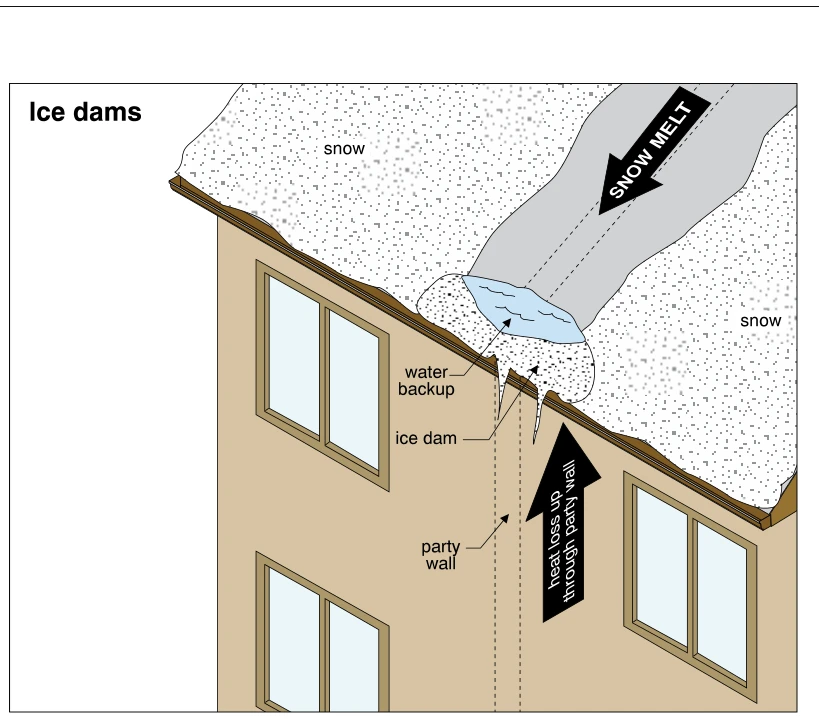
2016Ice dams
· p. 356
The illustration shows a snow-covered sloping roof over adjoining dwellings separated by a party wall, whose location is indicated by dashed lines. An upward arrow identifies heat loss through the party wall, aligned with a strip of melted snow on the roof. Meltwater flows down this strip toward an ice dam at the eave. Water backs up behind the ice dam, and icicles hang from the roof edge.
 2016.3
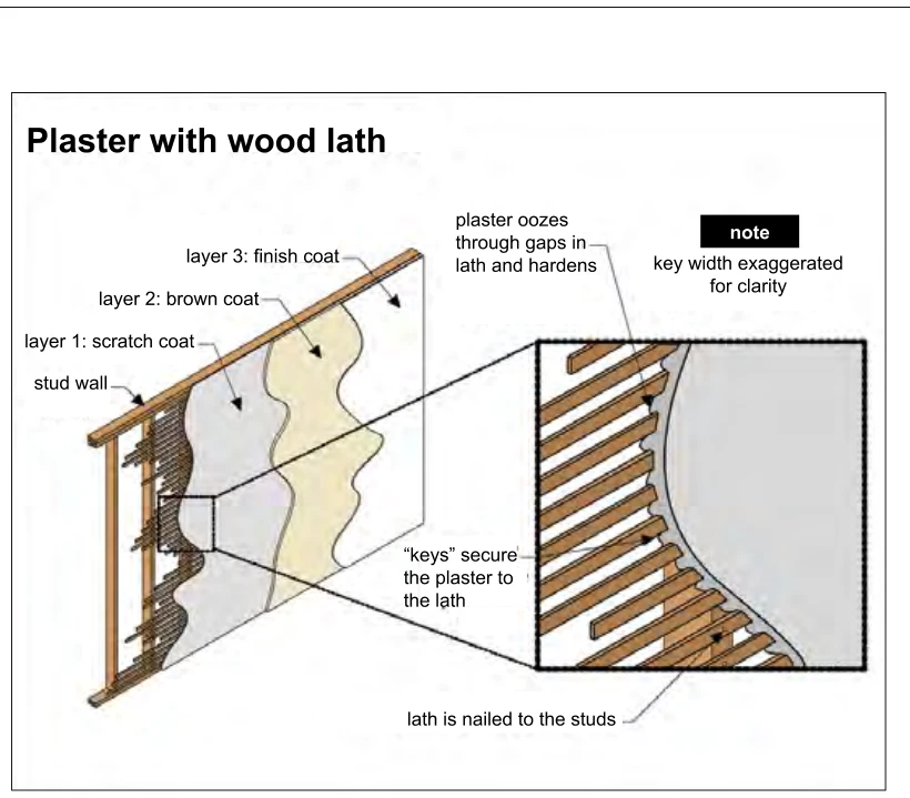
Plaster with wood lath
· p. 356
A cutaway stud wall shows three-coat plaster applied over horizontal wood lath nailed to the studs. The exposed layers are identified as the scratch coat, brown coat, and finish coat. An enlarged detail shows plaster passing through the gaps between lath strips and hardening into keys that mechanically secure the plaster to the lath. A note states that the key width is exaggerated for clarity. No defects are depicted.
 2016.6
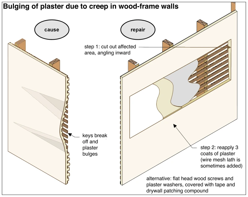
Bulging of plaster due to creep in wood-frame walls
· p. 356
The illustration compares bulging plaster on a wood-frame wall with a cutaway showing its repair. On the left, plaster keys have broken off behind the wood lath, allowing the plaster face to bulge outward. On the right, the affected plaster is cut out with inward-angled edges, exposing the horizontal wood lath. The repair is shown as three reapplied coats of plaster, with a note that wire mesh lath is sometimes added. An alternative repair is annotated using flat head wood screws and plaster washers covered with tape and drywall patching compound.
 2017
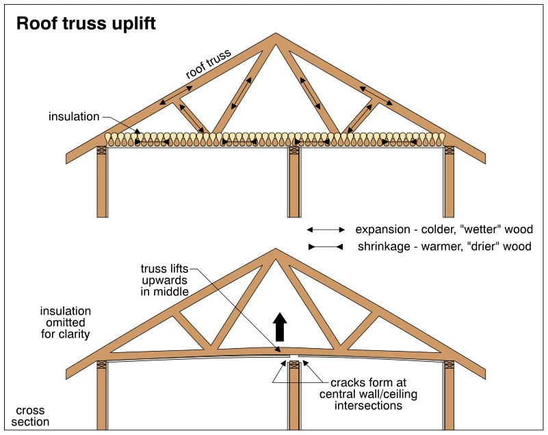
2017Roof truss uplift
· p. 356
Two cross sections illustrate roof truss uplift above an interior partition. The upper view shows a wood roof truss with insulation along its bottom chord and arrows indicating expansion of colder, wetter wood and shrinkage of warmer, drier wood. The lower view, with insulation omitted for clarity, shows the bottom chord bowed upward at the center while its ends remain supported at the exterior walls. The ceiling lifts away from the central partition, forming cracks at the wall/ceiling intersections.
 2018
2018Roof truss uplift - remedial action
· p. 357
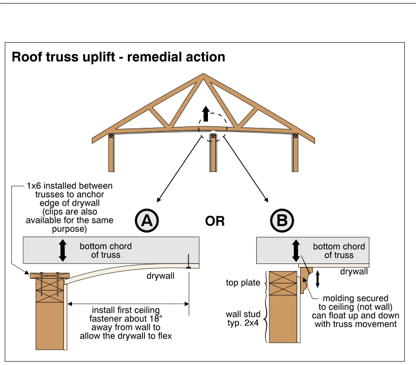
The illustration shows a roof truss lifting above an interior partition and two alternative remedial details at the ceiling-to-wall junction. Detail A uses a 1x6 installed between trusses, or clips, to anchor the drywall edge while locating the first ceiling fastener about 18 inches from the wall so the drywall can flex. Detail B shows molding secured to the ceiling rather than the wall, allowing it to move vertically with the truss. Arrows indicate upward truss movement and vertical movement at the junction.
 2019
2019Strapping the underside of trusses
· p. 357
The illustration compares two ceiling attachment methods beneath wood roof trusses, with front and side views of each. In arrangement A, drywall is attached directly to trusses spaced 24 inches on center, and the side view shows sagging between supports. Arrangement B adds strapping perpendicular to the truss bottom chords every 16 inches, with drywall attached to the strapping and shown flat. The strapping is identified as 1x3s or 2x2s and described as better practice. A note states that some builders use 5/8-inch drywall to reduce sagging instead of strapping, while others use both methods.
 2020
2020Stairway lighting
· p. 357
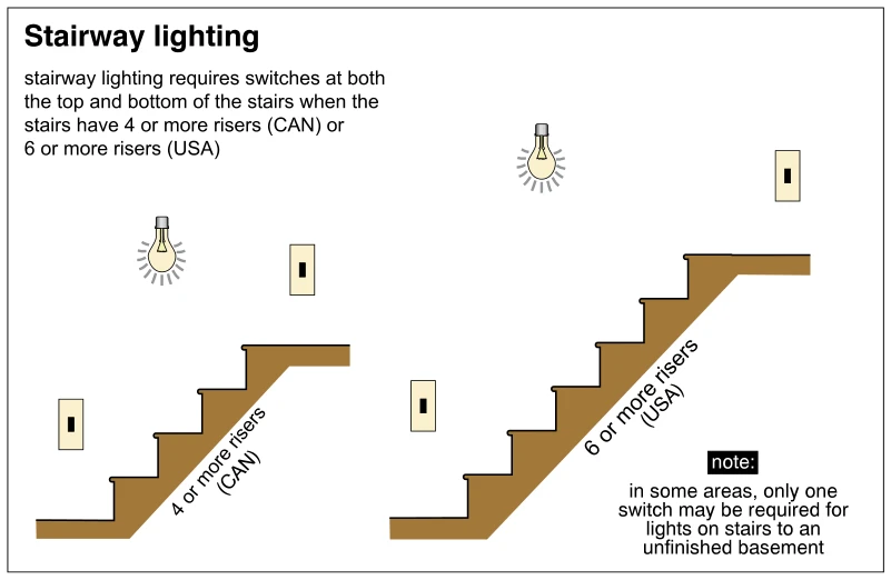
Two schematic stair profiles illustrate stairway lighting with switches at both the upper and lower ends of each flight. Each stairway is shown with an illuminated bulb and two wall switches. The Canadian example is labeled for stairs with four or more risers, while the USA example is labeled for six or more risers. A note states that some areas may require only one switch for lights on stairs to an unfinished basement.
 2020.5
Sagging ceiling – broken keys
· p. 357
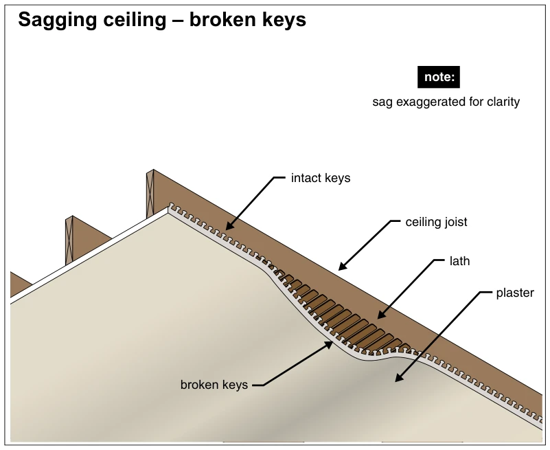
The cutaway illustration shows a plaster ceiling supported by wood lath beneath ceiling joists. Intact plaster keys extend through the gaps between lath strips and hold the plaster in place along the adjacent ceiling areas. In the central area, broken keys have allowed the plaster to separate from the lath and sag downward, exposing the lath above. A note states that the sag is exaggerated for clarity.
Stairsp. 358
 2021
2021Kinds of trim
· p. 358
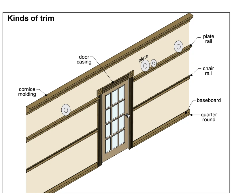
The illustration shows an interior wall with a glazed door and several types of decorative trim. Cornice molding runs along the top of the wall, and door casing surrounds the door opening. A plate rail supports displayed plates above a lower chair rail, with both rails interrupted by the doorway. Baseboard runs along the bottom of the wall, with quarter-round molding at its lower edge. The drawing identifies trim types and their locations without depicting defects.
 2022
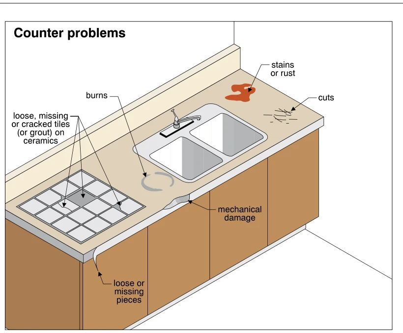
2022Counter problems
· p. 358
The illustration shows a kitchen countertop over base cabinets, with a double-bowl sink, faucet, and raised backsplash. A tiled section at the left illustrates loose, missing, or cracked ceramic tiles or grout. The surrounding counter surface has burn marks, stains or rust, and cuts. The front counter edge shows localized mechanical damage and a loose or missing section of edging.
 2023
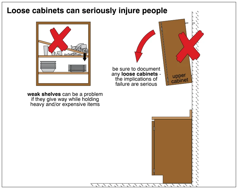
2023Loose cabinets can seriously injure people
· p. 358
The illustration shows two unsafe cabinet conditions, each marked with a red X. At left, a cabinet shelf has given way beneath stored items, with dishes on the shelf below. At right, an upper cabinet is pulling away from the wall above a base cabinet and countertop; a curved arrow indicates its potential fall. The annotations warn of shelf failure under heavy or expensive items and emphasize documenting loose cabinets because failure can seriously injure people.
 2023.5
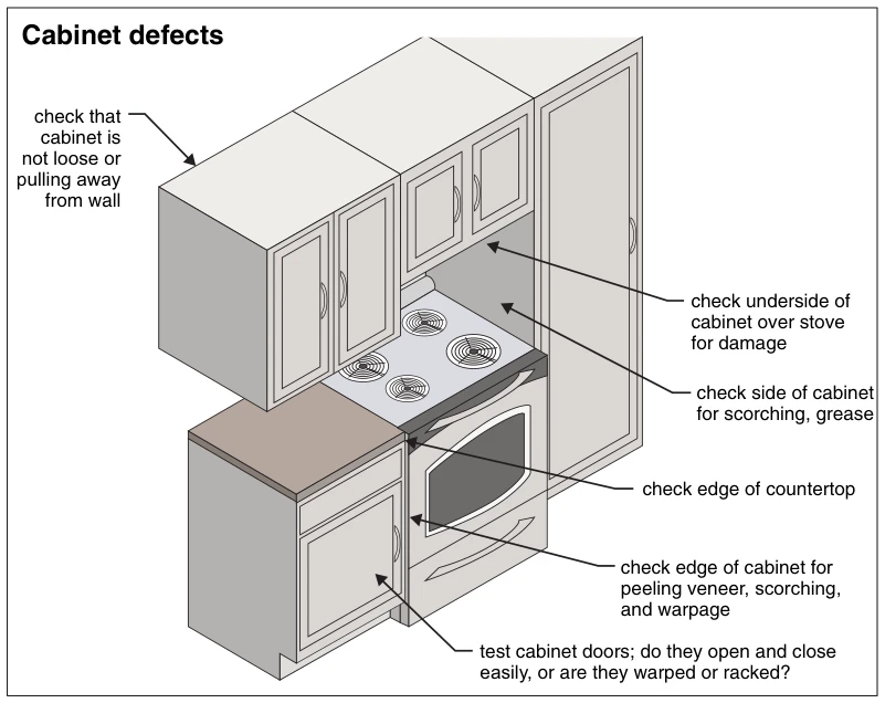
Cabinet defects
· p. 358
The illustration shows kitchen wall cabinets, a base cabinet and countertop, and a tall cabinet arranged around an electric range. Arrows identify inspection points at the wall cabinets, the underside of the cabinet above the stove, and the tall cabinet side adjacent to the cooking surface. Additional callouts direct attention to the countertop edge and the base cabinet edge for damage, peeling veneer, scorching, and warpage. The annotations also recommend checking cabinet attachment and testing doors for ease of operation, warping, or racking; specific damage is not visibly illustrated.
 2024
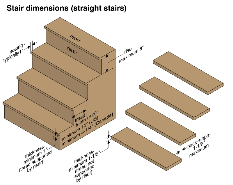
2024Stair dimensions (straight stairs)
· p. 358
The illustration shows a straight flight of closed-riser stairs beside a separate arrangement of open-riser treads. The closed-riser assembly identifies the tread, riser, nosing projection, vertical rise, and horizontal tread depth or run. Printed dimensions specify a typical 1-inch nosing, an 8-inch maximum rise, and minimum runs of 10 inches in the US and 8-1/4 inches in Canada. Tread thickness is shown as a minimum of 1 inch when supported by a riser and 1-1/2 inches when not supported by a riser. The open-riser arrangement also identifies a maximum 1-1/2-inch back-slope using horizontal dimension arrows between adjacent tread edges.
 2025
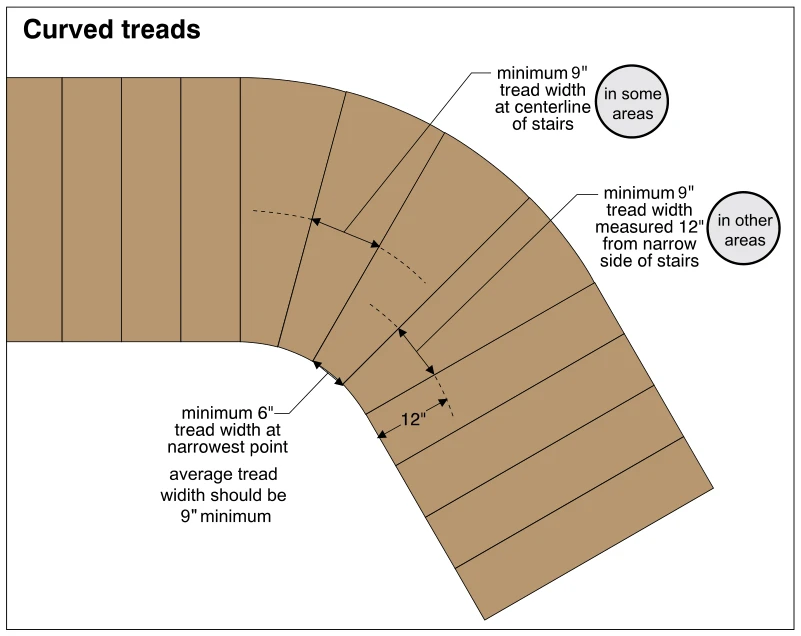
2025Curved treads
· p. 358
The illustration shows a plan view of a stair flight that changes direction through a series of tapered, curved-stair treads. The treads are narrower along the inside of the curve and wider along the outside. Dimension arrows indicate a minimum tread width of 6 inches at the narrowest point and an average tread width of at least 9 inches. Alternative regional criteria call for a minimum 9-inch tread width either at the stair centerline or at a line measured 12 inches from the narrow side of the stairs. Dashed lines and arrows identify the measurement locations.
 2026
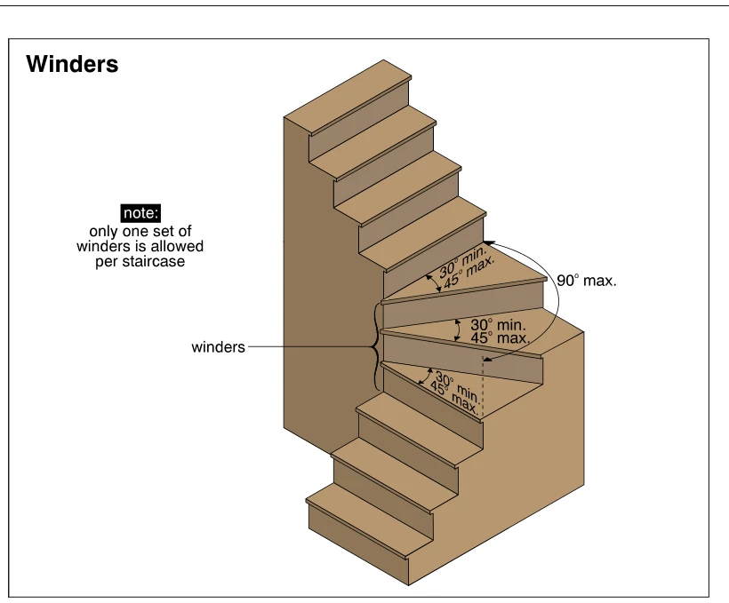
2026Winders
· p. 359
The illustration shows an interior staircase with straight treads above and below a set of three wedge-shaped winder treads. The winders change the direction of the stair without an intermediate landing, narrowing toward the inside of the turn. Each winder is annotated with a minimum angle of 30° and a maximum of 45°, and the overall turn is labeled 90° maximum. A note states that only one set of winders is allowed per staircase.
 2027
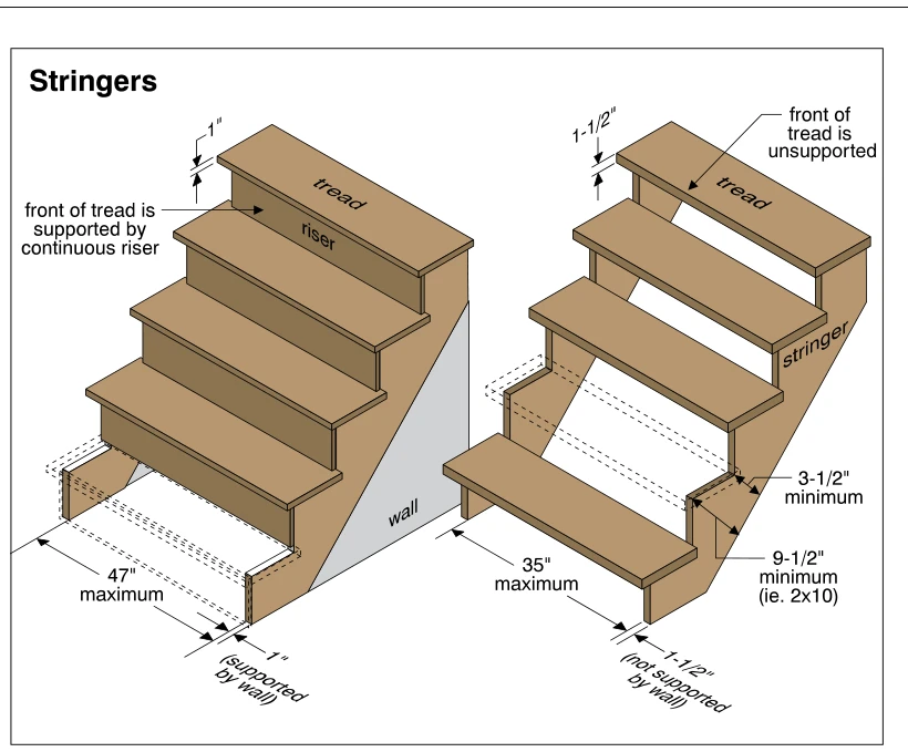
2027Stringers
· p. 359
The illustration compares wood stair assemblies with closed risers and open risers, showing tread spans and stringer dimensions. On the left, continuous risers support the fronts of 1-inch-thick treads, with a 47-inch maximum span and a 1-inch-thick stringer supported by a wall. On the right, the open-riser assembly leaves the tread fronts unsupported and specifies 1-1/2-inch-thick treads with a 35-inch maximum span. The unsupported stringer is shown as 1-1/2 inches thick, with a 9-1/2-inch minimum overall depth and at least 3-1/2 inches of wood remaining beneath the tread-and-riser notches.
 2028
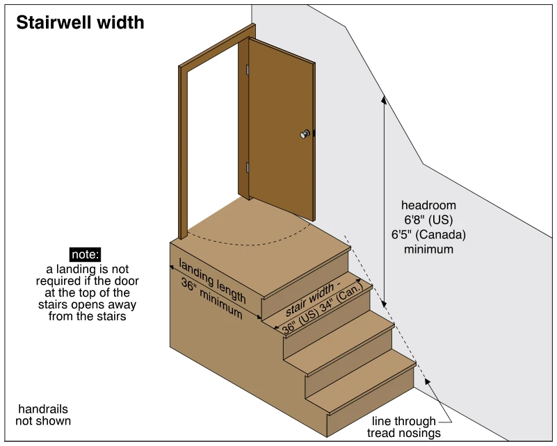
2028Stairwell width
· p. 359
The illustration shows an interior stair flight leading to a landing and a hinged door at the top. Dimension arrows identify a minimum landing length of 36 inches and stair widths of 36 inches for the US and 34 inches for Canada. A vertical headroom dimension extends above a dashed line through the tread nosings, with minimums labeled 6 feet 8 inches for the US and 6 feet 5 inches for Canada. A dashed arc indicates the door swing over the landing, and a note states that a landing is not required if the door opens away from the stairs. Handrails are explicitly omitted from the drawing.
 2029
2029Handrails and guards
· p. 359
The illustration shows an interior stair flight with a sloping handrail, balusters, newel posts, and a horizontal landing guard. Stair handrail height is identified as typically 34 to 38 inches above a line through the tread nosings, while the landing guard is labeled typically 36 inches high. A magnified detail shows a maximum 4-inch opening between balusters. A wall-mounted handrail cross section illustrates an easily gripped round or oval profile, a 1¼- to 2-inch size, and typically 1½ inches minimum clearance from the wall. A plan detail shows a handrail returning to the wall when it does not terminate at a post, and an annotation recommends a handrail where there are more than two or three risers.
 2030
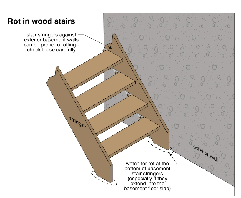
2030Rot in wood stairs
· p. 360
The illustration shows an open-riser wooden basement stair with treads supported between two inclined stringers. One stringer runs directly against an exterior basement wall. A callout identifies this wall-adjacent stringer as susceptible to rot and recommends careful inspection. Dashed outlines highlight the bottoms of both stringers, where another annotation warns of rot, particularly if the wood extends into the basement floor slab. The drawing identifies vulnerable locations rather than showing detailed visible decay.
 2031
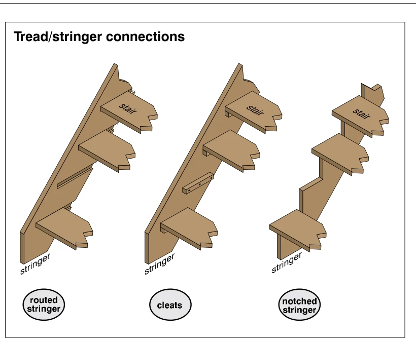
2031Tread/stringer connections
· p. 360
The illustration shows three methods of connecting wooden stair treads to inclined stringers. At left, tread ends fit into routed recesses in the side of a solid stringer, with an exposed recess showing the connection profile. In the center, treads rest on cleats attached to the inside face of a solid stringer. At right, treads bear on the horizontal cuts of a notched stringer. Portions of the treads are cut away for clarity, and no defective connections are identified.
 2032
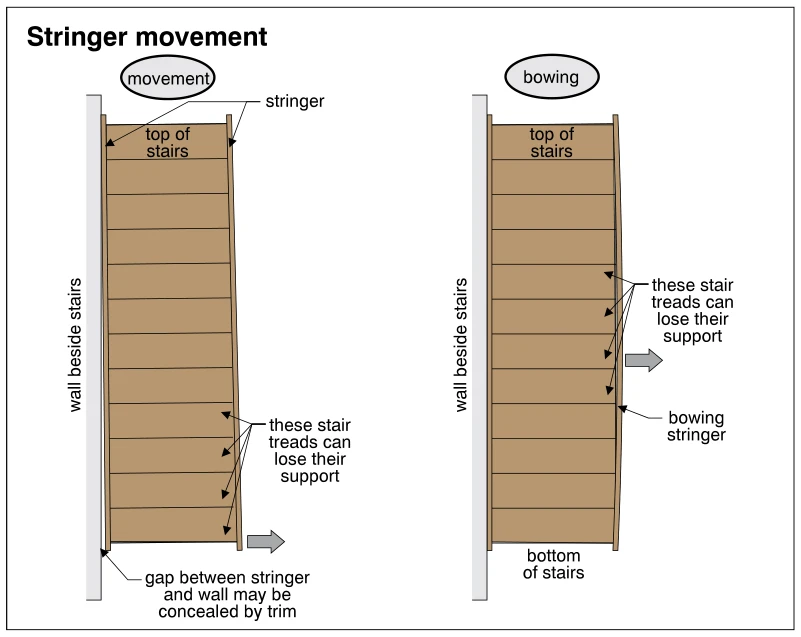
2032Stringer movement
· p. 360
Two plan-view diagrams show movement of interior stair stringers alongside a wall. The left diagram depicts sideways displacement that creates a gap between the wall and stringer near the bottom of the stairs; the annotation notes that trim may conceal this gap. The right diagram shows the outer stringer bowing outward near the middle of the stair flight. Both diagrams identify stair treads that can lose their end support as the stringer moves away.
 2033
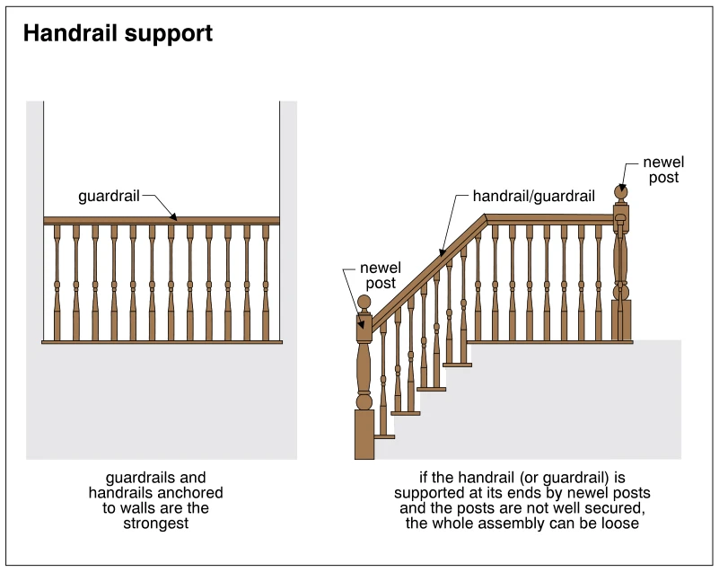
2033Handrail support
· p. 360
The illustration compares a wall-anchored guardrail with a stair handrail/guardrail supported by newel posts. On the left, a horizontal rail and vertical balusters span between two walls; the annotation identifies wall anchorage as the strongest support. On the right, a rail follows the stair slope and continues horizontally along the landing, with balusters below and newel posts at its ends. The annotation warns that poorly secured newel posts can leave the entire railing assembly loose.
Windows, Skylights and Solariumsp. 361
 2034
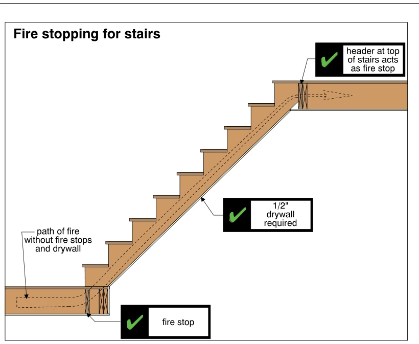
2034Fire stopping for stairs
· p. 361
The illustration shows a section through an interior stair flight connecting two framed floor levels. A fire stop closes the concealed space at the bottom of the stairs, and the header at the top acts as a fire stop at the upper floor connection. A continuous layer beneath the inclined stair assembly is labeled as required 1/2-inch drywall. Dashed arrows trace the potential path of fire through the concealed floor and stair spaces without these protective measures. Green check marks identify the fire stops and underside drywall as correct provisions.
 2035
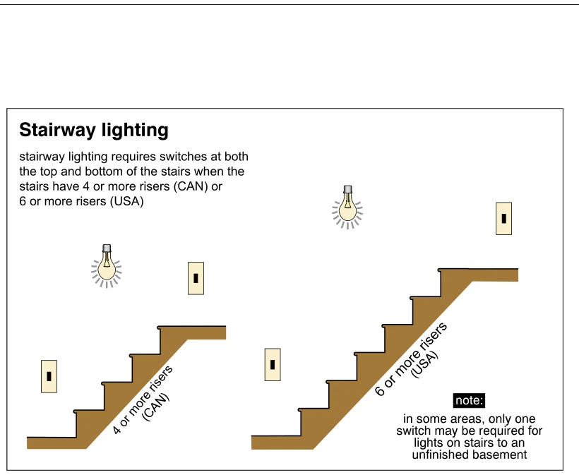
2035Stairway lighting
· p. 361
The illustration shows two schematic side views of interior stair flights, each with a light and switches at the top and bottom. The left flight is labeled for four or more risers in Canada, and the right for six or more risers in the USA. The annotation states that stairway lighting requires switches at both ends for these riser counts. A note identifies a possible local exception allowing only one switch for lights on stairs to an unfinished basement.
 2036
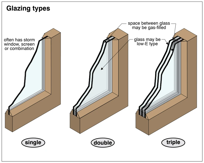
2036Glazing types
· p. 361
Three cutaway window assemblies compare single, double and triple glazing in brown frames. The single-glazed assembly has one glass pane and is annotated as often having a storm window, screen or combination. The double- and triple-glazed assemblies show two and three parallel panes respectively, separated by spaces. Callouts indicate that the spaces between glass may be gas-filled and that the glass may be low-E type. No defects or installation failures are depicted.
 2037
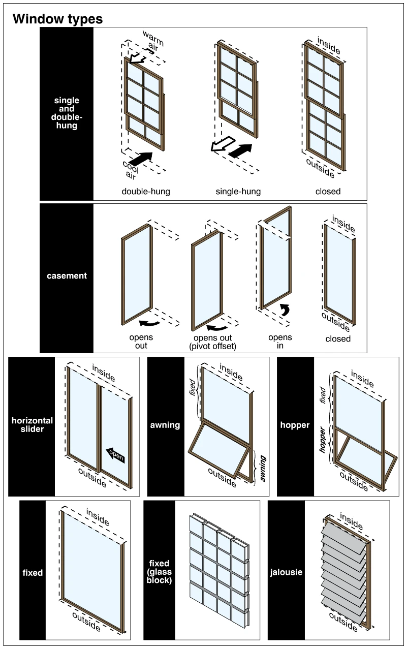
2037Window types
· p. 361
The illustration identifies common residential window types and shows their opening motions relative to the inside and outside. Single- and double-hung windows have vertically sliding sashes, with arrows at the double-hung window showing warm air leaving above and cool air entering below. Casement examples swing outward, outward with an offset pivot, or inward, while a horizontal slider opens sideways. An awning sash swings outward from its top edge beneath a fixed pane, and a hopper sash tilts inward from its bottom edge beneath a fixed pane. The remaining examples show fixed glazing, a glass-block window, and a jalousie window with multiple tilted horizontal louvers.
 2038
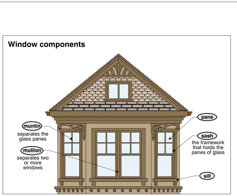
2038Window components
· p. 362
The illustration shows a decorative gabled facade with paired central windows, narrow windows on either side, and a small window in the gable. Callouts identify a pane as an individual area of glass and the sash as the framework holding the glass panes. A muntin separates panes within a sash, while a mullion separates the two central windows. A sill is identified at the base of the right-hand window. The drawing explains window terminology without depicting defects.
 2039
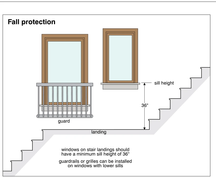
2039Fall protection
· p. 362
The illustration shows two windows above a stair landing, with stairs descending to the left and ascending to the right. The right window has a sill dimensioned 36 inches above the landing. The left window has a lower sill and is protected by a guard with closely spaced vertical bars. The annotations present a minimum 36-inch sill height for windows on stair landings and identify guardrails or grilles as protection for lower-sill windows.
 2040
2040Drain holes
· p. 362
The illustration shows a cross-section through window sashes and glass seated over a multi-track frame on a sill. Drain holes through the exterior-side tracks provide a path for water to escape toward the outside. A dashed arrow traces water flowing through these openings and off the exterior side of the frame. An annotation warns that debris can plug the drain holes, allowing water to back up over the tracks and enter the interior.
 2041
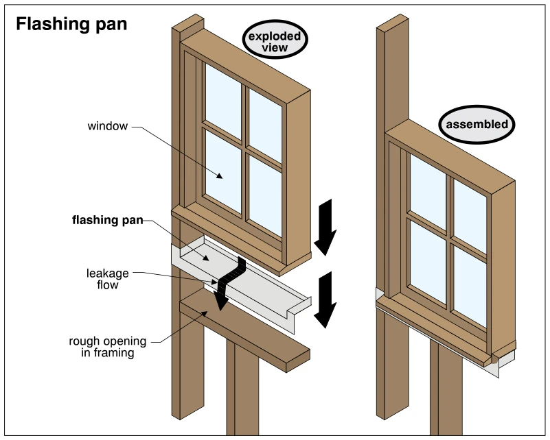
2041Flashing pan
· p. 362
The illustration shows exploded and assembled views of a window installed over a flashing pan in a wood-framed rough opening. The exploded view places the pan between the window sill and the framing below, with downward arrows indicating assembly. The pan has raised edges and a downturned front apron, and a leakage-flow arrow shows water draining over its front edge. The assembled view shows the pan extending beneath the window to direct leakage away from the underlying framing.
 2042
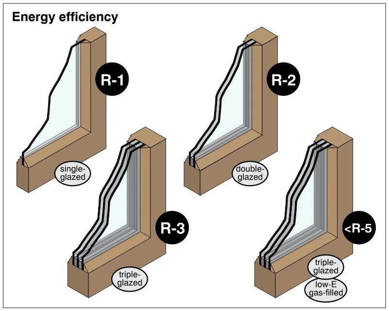
2042Energy efficiency
· p. 362
Four cutaway window corners compare the thermal resistance of different glazing configurations. Single glazing is labeled R-1, double glazing R-2, and triple glazing R-3. A fourth assembly, labeled triple-glazed and low-E gas-filled, is marked <R-5. The sections show successive glass panes and intervening spaces seated within the window frames, illustrating improved insulating performance with additional glazing and enhanced glazing technology.
 2043
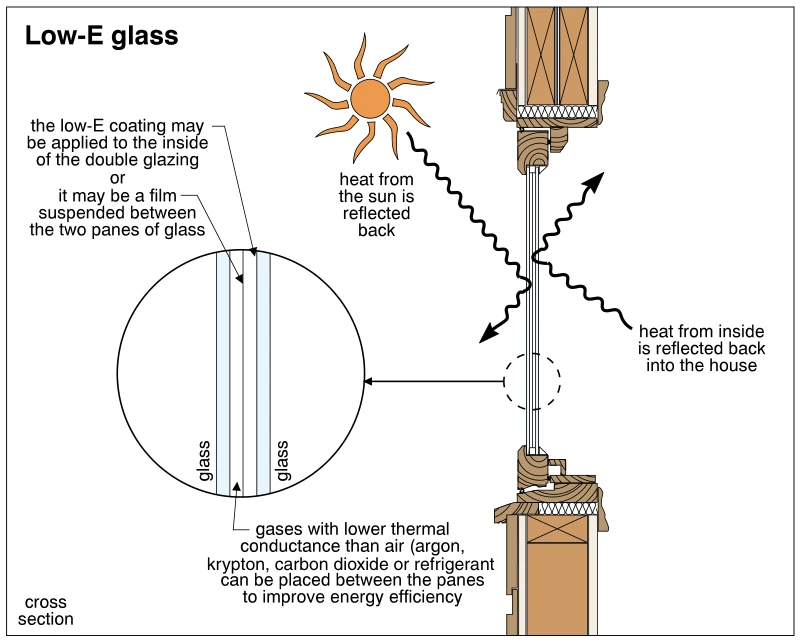
2043Low-E glass
· p. 362
The illustration shows a cross section through a double-glazed window set in a framed wall, with an enlarged detail of the glazing. The detail identifies two glass panes and indicates that a low-E coating may be applied inside the double glazing or provided as a film suspended between the panes. Wavy arrows show solar heat reflected outward and heat from inside reflected back into the house. An annotation explains that gases with lower thermal conductance than air can be placed between the panes to improve energy efficiency.
 2044
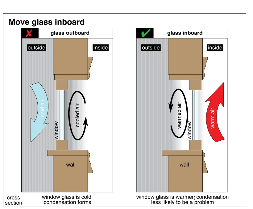
2044Move glass inboard
· p. 363
Two cross sections compare window glass positioned toward the exterior and toward the interior of a wall. The outboard arrangement is marked with a red X and shows cold exterior air and a cooled-air circulation loop beside the recessed interior glass surface. Its caption states that the glass is cold and condensation forms. The inboard arrangement is marked with a green check and shows warm interior air passing close to the glass, with a warmed-air circulation loop on the exterior side. Its caption states that the glass is warmer and condensation is less likely to be a problem.
 2045
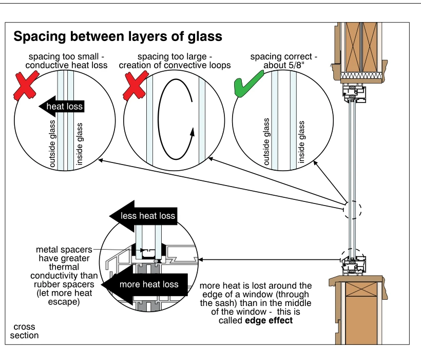
2045Spacing between layers of glass
· p. 363
The illustration shows a cross section of a double-glazed window with enlarged details comparing spacing between the glass layers. A narrow gap is marked incorrect because of conductive heat loss, while an overly wide gap is marked incorrect because it creates convective loops. A gap of about 5/8 inch is marked correct. An enlarged edge detail shows greater heat loss through the sash and glazing edge than through the middle of the glass, identified as the edge effect. An annotation explains that metal spacers conduct more heat than rubber spacers.
 2046
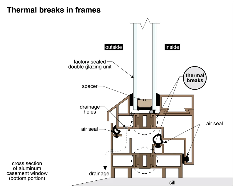
2046Thermal breaks in frames
· p. 363
The illustration shows a cross section through the bottom portion of an aluminum casement window, with the outside on the left and the inside on the right. A factory-sealed double glazing unit with a spacer is supported within the window sash. Thermal breaks separate exterior and interior portions of the aluminum sash and frame to interrupt conductive heat transfer. Air seals are shown at the sash-to-frame interfaces, while drainage holes and a dashed drainage path direct water toward the exterior above the sill.
 2047
2047Look behind window treatments
· p. 363
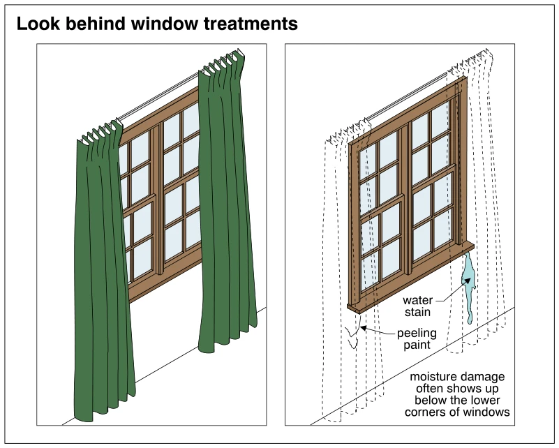
Two interior views show a wood-framed, divided-light window with curtains hanging at either side. The left view shows how the curtains conceal the wall beneath the lower window corners. In the right view, the curtains are drawn in dashed outline to reveal peeling paint below the left corner and a water stain below the right corner. The illustration emphasizes looking behind window treatments for otherwise concealed evidence of moisture damage.
 2048
2048Sloped glazing
· p. 364
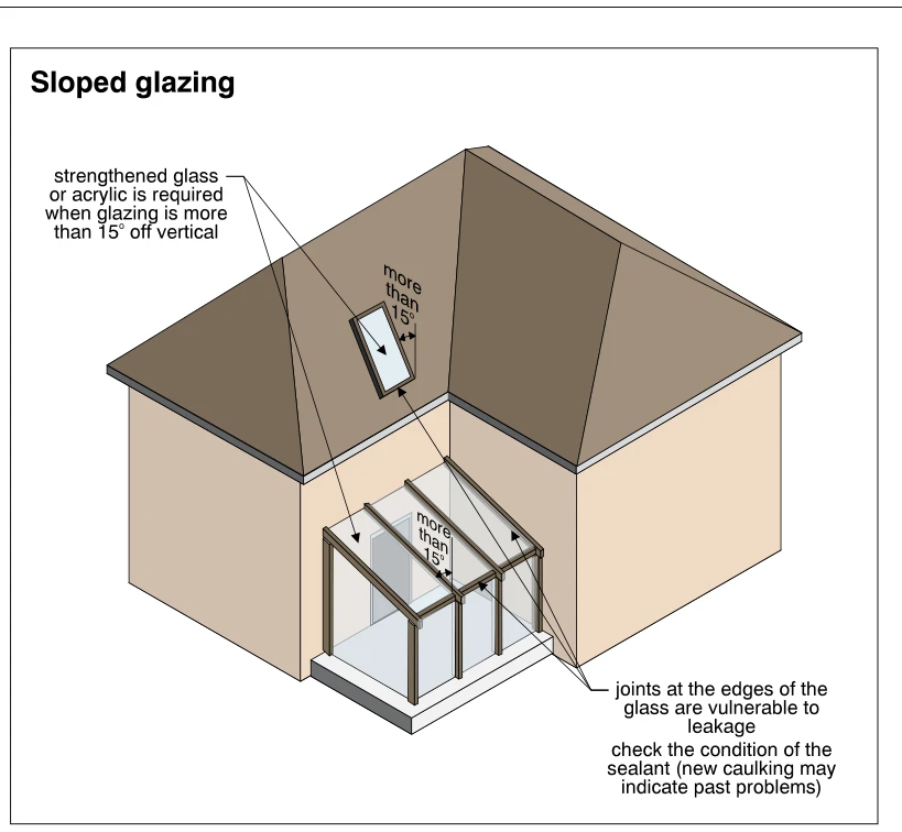
The illustration shows a house with a roof-mounted skylight and an attached solarium with sloped roof glazing and vertical glazed walls. Both the skylight and solarium roof glazing are marked as more than 15° off vertical, with a note requiring strengthened glass or acrylic for this orientation. Framing supports the solarium glazing and divides it into individual panels. Callouts identify joints at the glass edges as vulnerable to leakage and advise checking the sealant, noting that new caulking may indicate past problems. No actual leakage or sealant deterioration is shown.
 2049
2049Skylight and solarium leaks
· p. 364
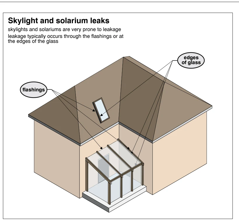
The illustration shows a house with a skylight set into a sloped roof and an attached glazed solarium at an inside corner of the exterior walls. The solarium has sloping glass roof panels supported by framing above vertical glazed walls. Arrows identify flashings and glass edges at both the skylight and solarium as typical leakage locations. The annotations warn that these assemblies are prone to leakage, although no active leakage or resulting damage is shown.
 2050
2050Lintels sagging or missing
· p. 364
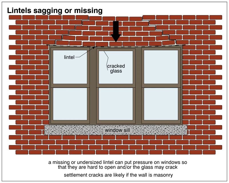
The illustration shows a three-section window set in a brick masonry wall above a projecting sill. The lintel and masonry above the opening sag toward the center, with a large downward arrow indicating pressure on the window assembly. Stepped settlement cracks extend through mortar joints above both sides of the opening. The upper pane of the center window is cracked. The annotations explain that a missing or undersized lintel can load the windows, making them difficult to open and potentially cracking the glass.
 2051
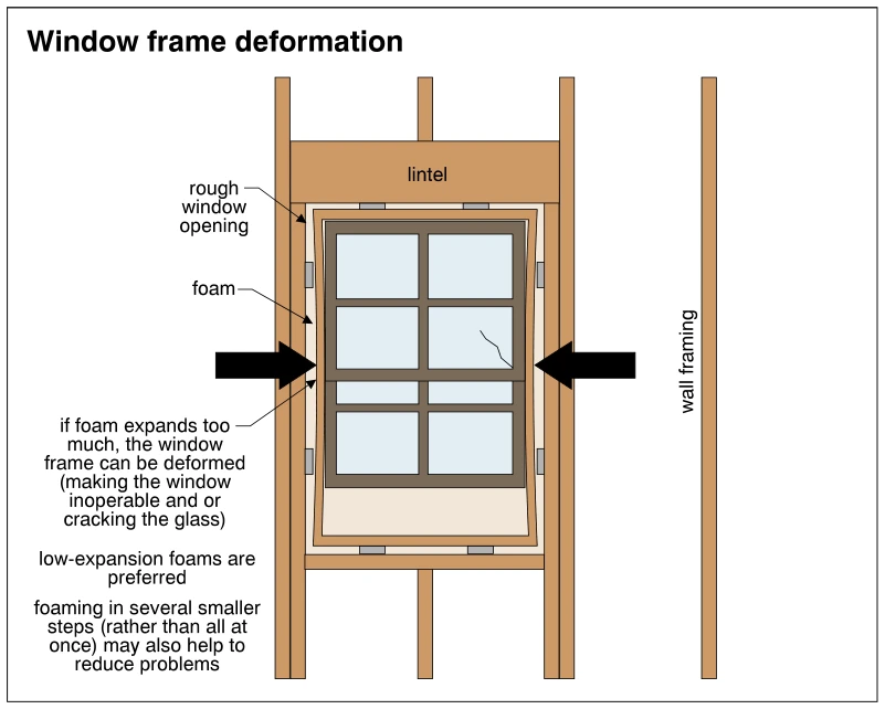
2051Window frame deformation
· p. 364
The illustration shows a window installed in a wood-framed rough opening beneath a lintel, with foam between the window frame and the surrounding framing. Large inward-pointing arrows indicate pressure from expanding foam, and the window frame sides are shown bowed inward. A crack is visible in one glass pane. The annotations warn that excessive foam expansion can deform the frame, prevent window operation, or crack the glass, and recommend low-expansion foam and application in several smaller steps.
 2052
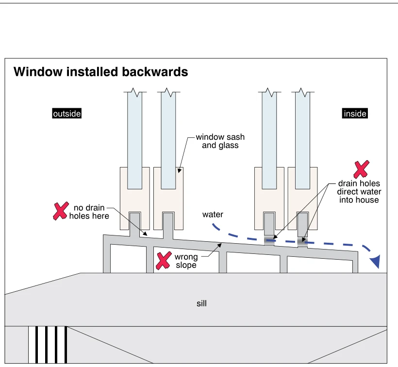
2052Window installed backwards
· p. 365
The illustration shows a cross-section of a window installed backwards, with the outside on the left and the inside on the right. Window sashes and glass sit above a sloped lower frame supported on a sill. The lower frame slopes toward the interior rather than the exterior, and its drain holes are on the inside. A dashed blue arrow traces water flowing through these holes into the house, while red crosses identify the missing exterior drain holes, incorrect slope, and inward drainage.
 2053
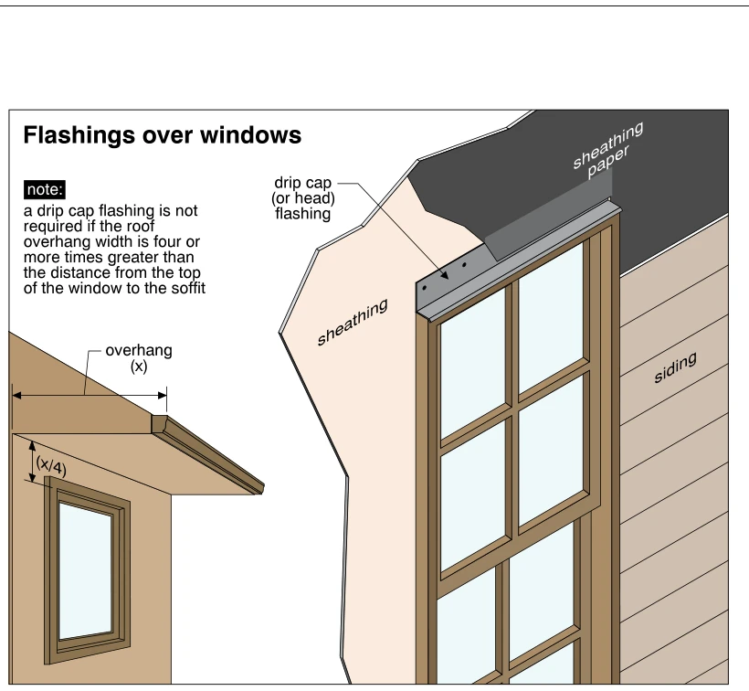
2053Flashings over windows
· p. 365
The main drawing shows an exterior window head with drip cap flashing installed above the wood trim. The flashing has an upright back leg against the wall sheathing and a projecting lip over the window head, with sheathing paper overlapping its upper portion. Horizontal siding is shown beside the window. A smaller diagram compares roof overhang width with the vertical distance from the window top to the soffit. The printed note states that drip cap flashing is not required when the overhang width is four or more times that distance.
 2054
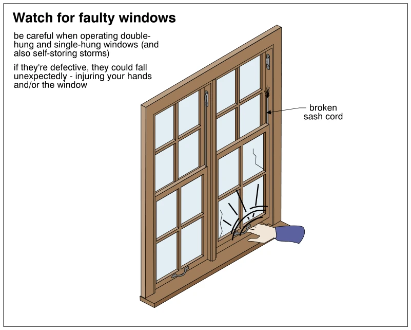
2054Watch for faulty windows
· p. 365
The illustration shows two adjacent divided-light hung windows in a wood frame. A callout identifies a broken sash cord along the right-hand window jamb. Motion lines show the lower sash falling toward a person's hand at the sill, and cracks are visible in the glazing. The annotations warn that defective double-hung, single-hung, and self-storing storm windows can fall unexpectedly, causing hand injuries or window damage.
 2055
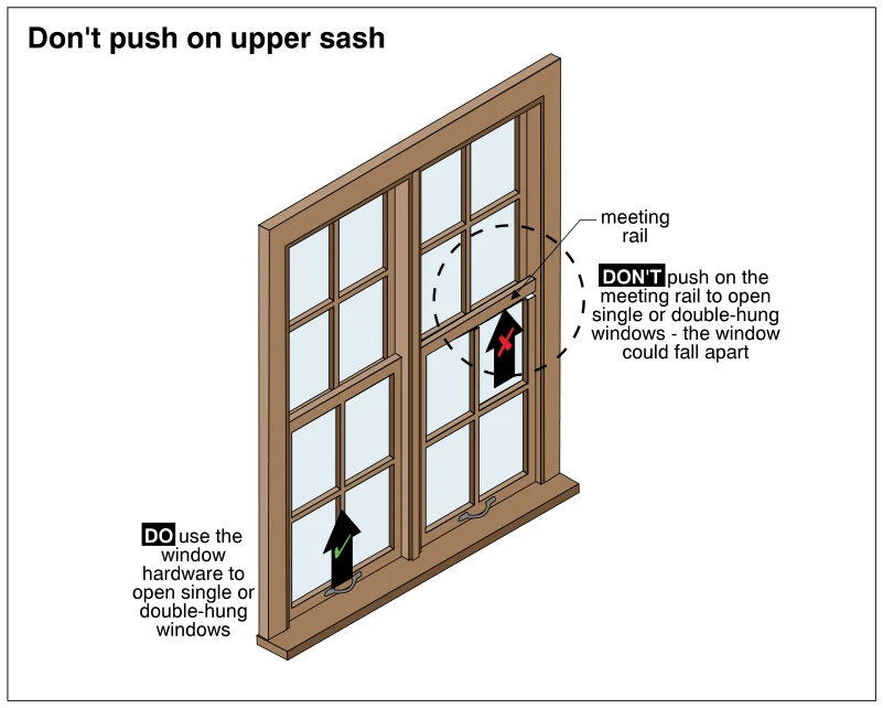
2055Don't push on upper sash
· p. 365
The illustration shows two adjacent divided-light sash windows with lifting hardware at the bottom of the lower sashes. A green check and upward arrow indicate opening a window using its lifting hardware. On the right, a dashed circle highlights the meeting rail, where an upward arrow and red cross mark pushing on the rail as improper. The annotation warns that pushing on the meeting rail to open a single- or double-hung window could cause the window to fall apart.
 2056
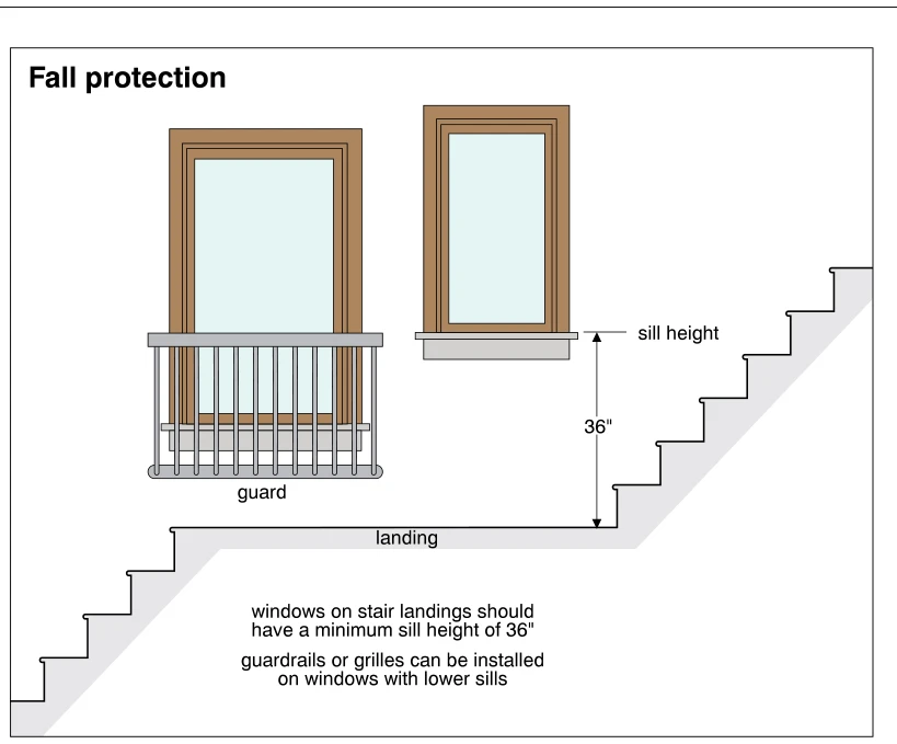
2056Fall protection
· p. 366
The illustration shows two windows beside a stair landing between two stair flights. The right window has a sill height dimension of 36 inches measured above the landing. The left window has a lower sill and a protective guard with vertical bars across its lower portion. The annotations specify a minimum 36-inch sill height for windows on stair landings and identify guardrails or grilles as protection for lower-sill windows.
 2057
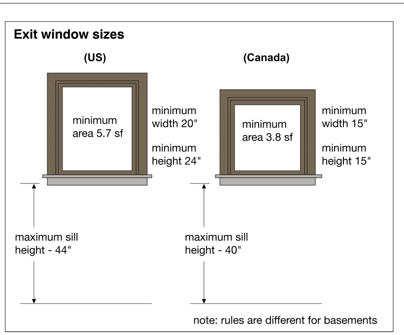
2057Exit window sizes
· p. 366
The illustration compares exit-window opening dimensions and maximum sill heights labeled for the US and Canada. The US example specifies a minimum opening area of 5.7 square feet, minimum width of 20 inches, minimum height of 24 inches, and maximum sill height of 44 inches. The Canadian example specifies a minimum opening area of 3.8 square feet, minimum width and height of 15 inches, and maximum sill height of 40 inches. Vertical arrows measure sill height from a floor reference line beneath each window. A note states that rules are different for basements.
 2058
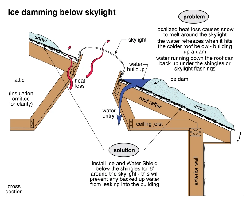
2058Ice damming below skylight
· p. 366
A roof cross section shows a domed skylight installed in a snow-covered sloped roof above an attic. Red arrows indicate localized heat loss around the skylight, which melts snow; the meltwater refreezes on the colder roof downslope to form an ice dam. Blue shading and arrows show water building up behind the dam and entering the building beneath the skylight flashing or shingles. Roof rafters, ceiling joists, and an exterior wall are shown, with insulation explicitly omitted for clarity. The illustrated solution calls for Ice and Water Shield beneath the shingles for six feet around the skylight to prevent backed-up water from leaking into the building.
 2058.3
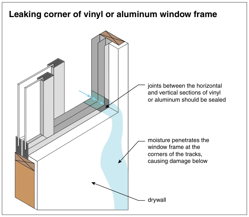
Leaking corner of vinyl or aluminum window frame
· p. 366
The illustration shows a cutaway of the lower corner of a vinyl or aluminum window frame above an interior drywall surface. The horizontal window tracks meet the vertical frame section at a corner joint. Blue arrows indicate moisture entering this joint, with a blue path extending down the drywall below to represent leakage and damage. The annotation specifies that joints between horizontal and vertical frame sections should be sealed.
Doorsp. 367
 2058.6
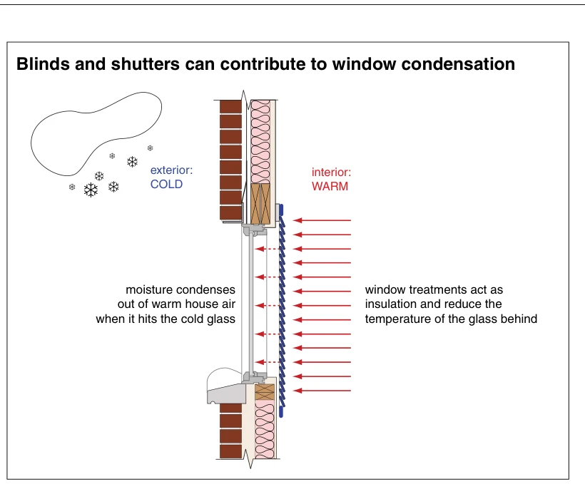
Blinds and shutters can contribute to window condensation
· p. 367
The illustration shows a vertical section through a window in an insulated, brick-clad wall, with cold conditions outside and warm conditions inside. A slatted window treatment covers the interior side of the glazing. Red arrows illustrate warm indoor air approaching the covering and the cold glass behind it. The annotations explain that blinds and shutters act as insulation, reducing the temperature of the glass behind them and contributing to condensation when warm house air contacts the cold glazing.
 2059
2059Door cores
· p. 367
The illustration shows an interior door and an exterior door with their top edges cut away to expose their cores. The flush interior door has wood veneer faces and cardboard reinforcement within its hollow core. The paneled exterior door has a metal face and a polyurethane insulation core, with a thermal break identified at the edge. Both doors have knobs and edge-mounted latch hardware. No defects or improper installation practices are depicted.
 2060
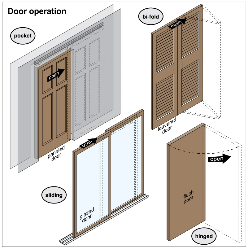
2060Door operation
· p. 367
The illustration shows four interior door operating configurations, with arrows and dashed outlines indicating opening movement. A paneled pocket door hangs from an overhead track and slides into a concealed wall pocket. A two-leaf louvered bi-fold door folds at its center joint. Two framed glazed sliding panels travel along parallel tracks, allowing one panel to overlap the other. A flush hinged door swings outward about one vertical edge; no defects are depicted.
 2061
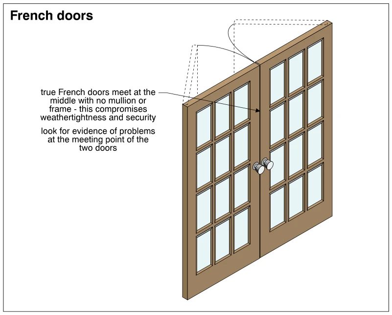
2061French doors
· p. 367
The illustration shows a pair of French doors with multiple rectangular glass panes in framed leaves and knobs adjacent to the central meeting line. The two leaves meet directly without a fixed center mullion or frame. Dashed outlines and curved lines above the doors indicate their swing. An annotation identifies the central joint as a potential weakness in weathertightness and security and directs inspection attention to the meeting point. No specific damage is depicted.
 2062
2062Lintels sagging or missing
· p. 368
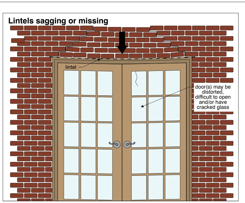
The illustration shows a pair of glazed doors in a brick masonry wall with a sagging lintel above the opening. A large downward arrow indicates loading over the center of the doorway, where the lintel and door-frame head bow downward. Stepped cracks follow mortar joints in the masonry above both sides of the opening. One glass pane in the right-hand door is cracked. The annotation identifies door distortion, difficulty opening, and cracked glass as possible consequences of sagging or missing lintels.
 2063
2063Insulated metal doors shouldn't have a storm door
· p. 368
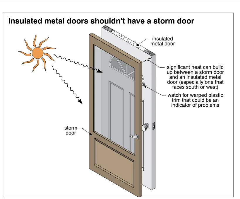
The illustration shows a glazed storm door installed in front of an insulated metal entry door, with the metal door's insulated core exposed at the top. A sun symbol and wavy arrows indicate solar heating of the assembly. The annotations warn that significant heat can accumulate between the doors, especially at south- or west-facing entrances. A callout identifies plastic trim on the metal door as a location to check for warping that could indicate heat-related problems.
 2064
2064Doorsill support
· p. 368
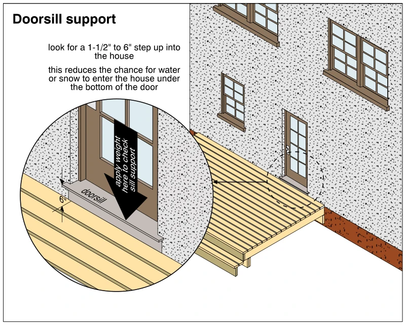
The illustration shows a glazed entry door opening onto a wood deck, with an enlarged detail of the doorsill. The sill is raised above the deck surface, and the annotations recommend a 1-1/2-inch to 6-inch step up into the house to reduce water or snow entry beneath the door. A vertical dimension at the enlarged sill is marked 6 inches. A downward arrow instructs the inspector to apply weight to the sill to check its support; no failed or damaged support is depicted.
 2065
2065Staining below exterior doors
· p. 368
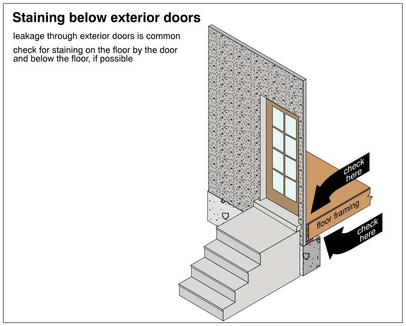
The illustration shows a cutaway of a glazed exterior door, adjacent wall, exterior steps and landing, and interior floor framing. Two arrows identify inspection locations at the floor beside the door and below the floor at the supporting framing. The annotations explain that leakage through exterior doors is common and recommend checking both locations for staining. No distinct water staining or deterioration is drawn; the figure identifies where evidence of leakage should be sought.
 2066
2066Door between garage and house (attached garage)
· p. 368
The illustration shows a door in the separation wall between an attached garage and the house interior, explicitly identified as not a bedroom. Green check marks indicate an exterior-type door, fire rated in some areas, with a self closer mounted at the top. Arrows indicate that the door should be tight fitting and weatherstripped. A dimension annotation shows a 6-inch step up from the garage into the house.
 2066.5
Racking door openings due to sloping/sagging floors
· p. 368
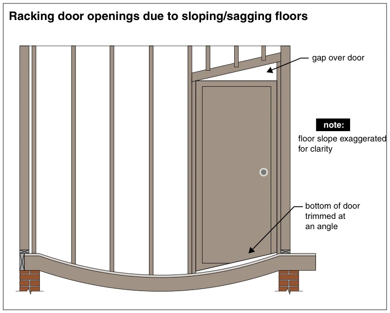
The illustration shows an exposed stud wall and door opening above a floor assembly that sags between two end supports. The sagging floor racks the door opening, leaving the framing above the door sloped relative to the horizontal door top. A wedge-shaped gap is visible above the door, widening toward the right. The bottom of the door has been trimmed at an angle to accommodate the sloping floor. A note states that the floor slope is exaggerated for clarity.
Wet Basements and Crawlspacesp. 369
 2067
2067Causes of wet basement problems
· p. 369
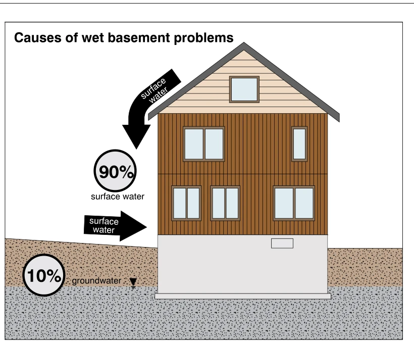
The illustration shows a house elevation with its basement foundation and footing exposed in a soil cross-section. Large arrows identify surface water descending beside the roof and moving toward the foundation along the ground. The ground on the left slopes toward the house. The diagram attributes 90% of wet basement problems to surface water and 10% to groundwater, shown in the deeper soil layer. No specific foundation crack or water-entry opening is depicted.
 2068
2068Roof and surface water control
· p. 369
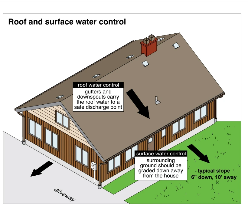
The illustration shows a house with gutters along the roof edges and downspouts at the corners for collecting and discharging roof runoff. A large arrow on the roof indicates water movement toward the eave. Arrows on the lawn and driveway indicate surface drainage away from the house. The annotations specify that surrounding ground should slope away from the foundation, with a typical fall of 6 inches over 10 feet, and that roof water should be carried to a safe discharge point.
 2069
2069Basement windows and stairs
· p. 369
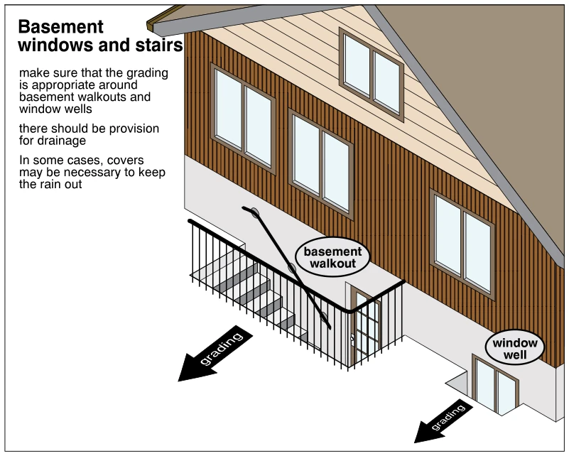
The illustration shows an exterior basement stairwell leading down to a basement door, with railings around the stair opening and a handrail along the wall. A nearby basement window sits below ground level within a recessed window well. Arrows labeled grading point away from the building beside both openings, emphasizing surface drainage away from these vulnerable areas. Notes call for appropriate grading, drainage provisions, and covers where necessary to keep rain out.
 2070
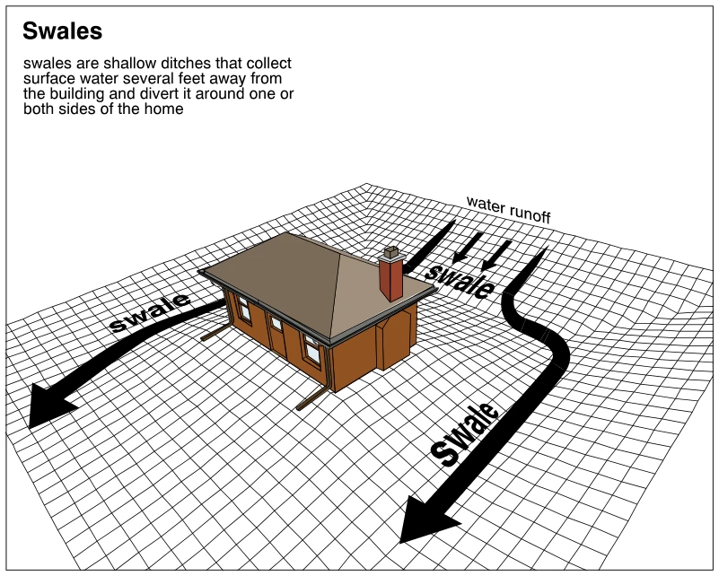
2070Swales
· p. 369
The illustration shows a house on a contoured site with shallow drainage swales located away from the building. Arrows indicate surface runoff flowing down the higher ground behind the house into the swales. Large arrows show the collected water being diverted around both sides of the house and toward lower ground. This depicts site grading that directs surface water away from the home rather than allowing it to collect against the foundation.
 2071
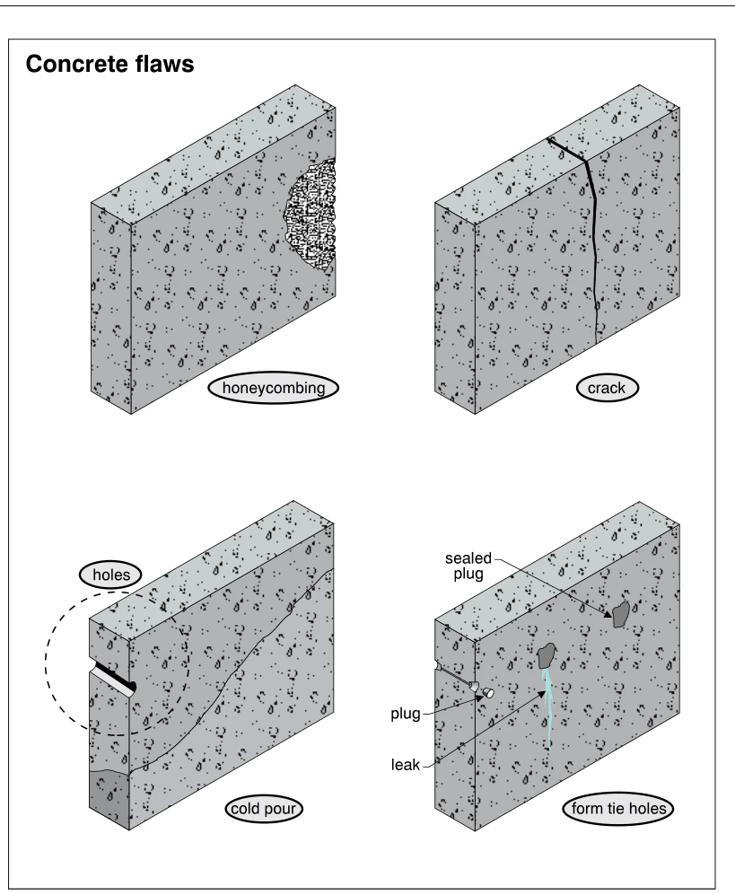
2071Concrete flaws
· p. 370
Four concrete wall sections illustrate flaws relevant to wet basements and crawlspaces. The upper-left section shows a localized area of honeycombing, while the upper-right section shows a crack extending across the top and down the wall face. The lower-left section shows a cold-pour joint and holes at the exposed edge. The lower-right section illustrates form tie holes with plugs, including a labeled sealed plug and water leaking beneath another plugged location.
 2072
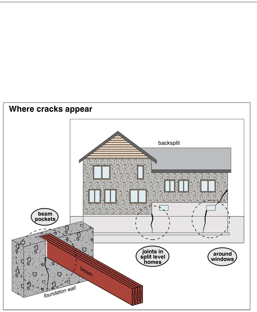
2072Where cracks appear
· p. 370
The illustration identifies common crack locations in basement foundation walls. An elevation of a backsplit house highlights cracking at a joint between differing foundation levels and around a basement window opening. A separate detail shows a built-up wood beam seated in a concrete foundation wall pocket, with a crack extending downward from the pocket. Dashed circles emphasize these locations where openings and changes in the foundation configuration interrupt the wall.
 2073
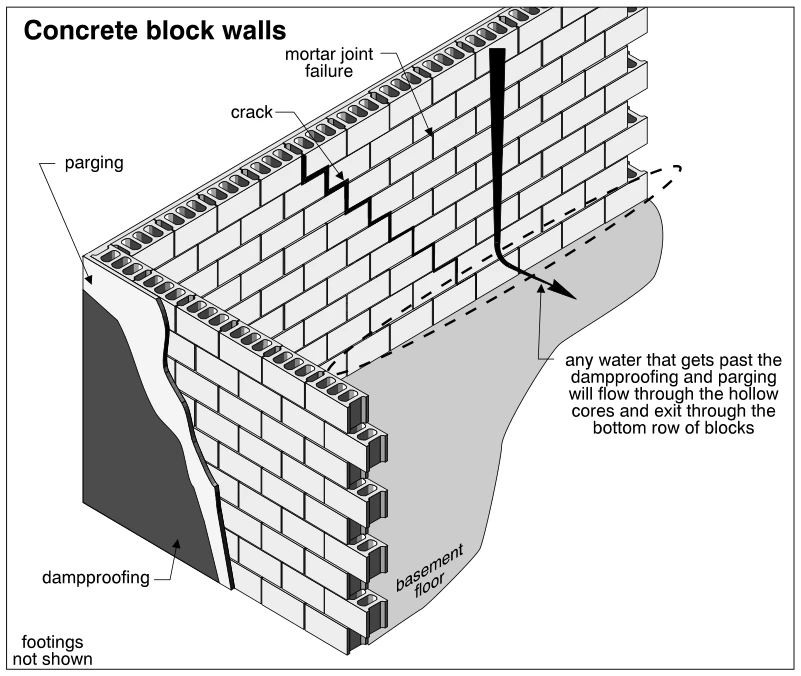
2073Concrete block walls
· p. 370
The cutaway shows intersecting hollow concrete block foundation walls beside a basement floor. Exterior parging and dampproofing are peeled back to reveal the wall assembly. A stair-step crack follows the block joints, and a separate callout identifies mortar joint failure. A heavy arrow illustrates water traveling down the hollow block cores and exiting through the bottom row of blocks after bypassing the dampproofing and parging. Footings are explicitly noted as not shown.
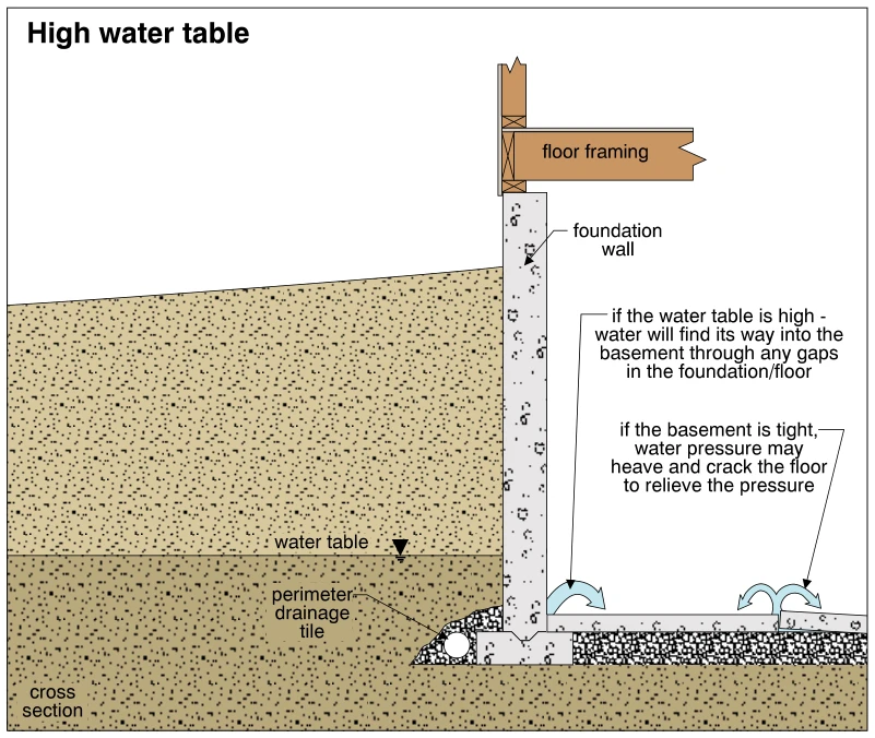 2074
2074High water table
· p. 370
The cross section shows a basement foundation wall and footing supporting wood floor framing, with a concrete basement floor over an aggregate layer. Exterior soil contains a water table above the basement floor level, and perimeter drainage tile is shown beside the footing. Arrows indicate groundwater entering through gaps at the foundation/floor junction and through the floor. The annotations explain that high groundwater can enter a basement through openings, or exert pressure that heaves and cracks the floor if the basement is tight.
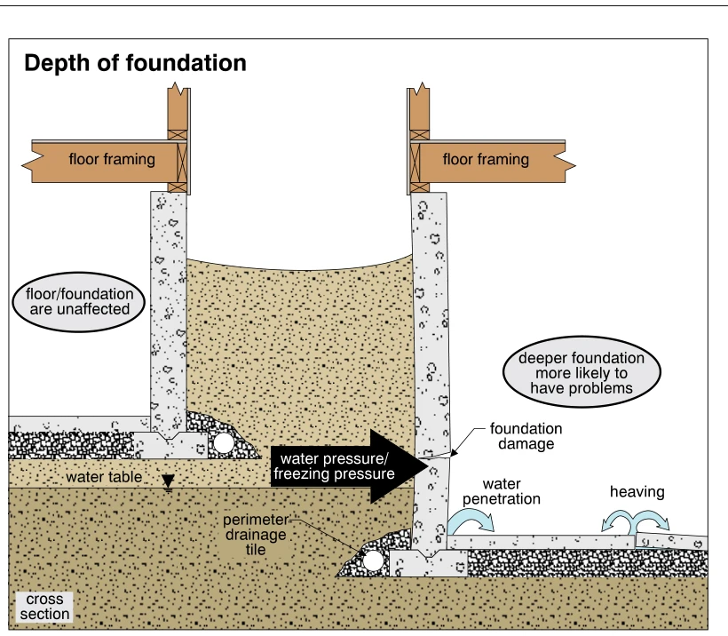 2075
2075Depth of foundation
· p. 371
The cross section compares shallow and deep concrete foundations supporting wood floor framing, with a water table below the shallow footing but above the deeper footing and slab. Both foundations have perimeter drainage tile beside their footings in granular bedding. The shallow floor and foundation are labeled as unaffected. At the deeper foundation, an arrow indicates water pressure/freezing pressure against the wall, where foundation damage is shown. Curved arrows indicate water penetration at the wall–floor junction and heaving of the cracked floor slab.
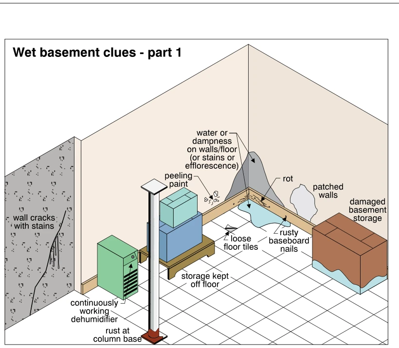 2076
2076Wet basement clues - part 1
· p. 371
The illustration shows a basement corner with numerous visible clues to moisture intrusion or persistent dampness. Wall clues include stained cracks, peeling paint, patched areas, and water, dampness, stains, or efflorescence at the wall and floor. Floor-level clues include loose tiles, rotted baseboard, rusty baseboard nails, and rust at the base of a support column. Stored boxes are shown both elevated on a platform and sitting in water with damaged lower edges. A continuously working dehumidifier is identified as another clue to a wet basement.
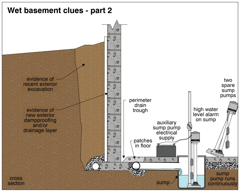 2077
2077Wet basement clues - part 2
· p. 371
The cross section depicts a basement foundation wall, floor slab, exterior soil, drainage piping, and a sump containing water and a pump. Exterior clues to past water problems include evidence of recent excavation and a new dampproofing or drainage layer against the foundation wall. Interior clues include a perimeter drain trough and patches in the floor. The sump installation includes an auxiliary electrical supply and a high-water-level alarm, with two spare sump pumps nearby. A note that the sump pump runs continuously identifies another clue to basement water problems.
 2078
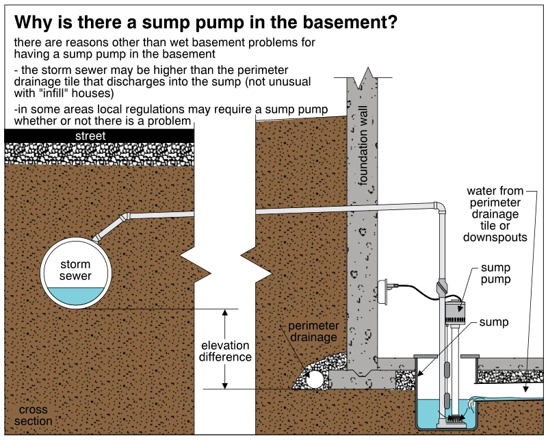
2078Why is there a sump pump in the basement?
· p. 371
A cross section shows a basement sump and pump beside a foundation wall, with a discharge pipe extending through the wall to a storm sewer beneath the street. Perimeter drainage is shown at the foundation footing, and an inlet carries water from perimeter drainage tile or downspouts into the sump. The storm sewer is higher than the foundation drainage, with the elevation difference marked by a vertical arrow. The pump lifts collected water to the sewer connection. The annotations explain that a sump pump can be needed because of sewer elevation or local regulations, rather than indicating an existing wet-basement problem.
 2079
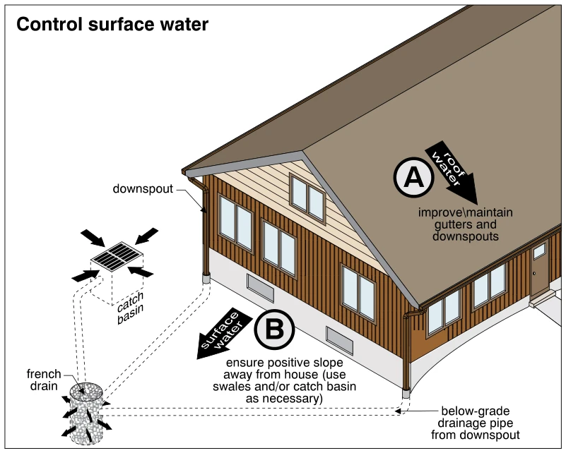
2079Control surface water
· p. 371
The illustration shows a house with two complementary measures for controlling water around the foundation. Roof water is collected by gutters and downspouts, with an annotation recommending their improvement or maintenance. Dashed lines show below-grade drainage pipes carrying downspout discharge away from the house to a labeled French drain. A grated catch basin also collects surface runoff and connects to the drainage arrangement. A separate annotation recommends positive slope away from the house, using swales or a catch basin as necessary to help keep basements and crawlspaces dry.
 2080
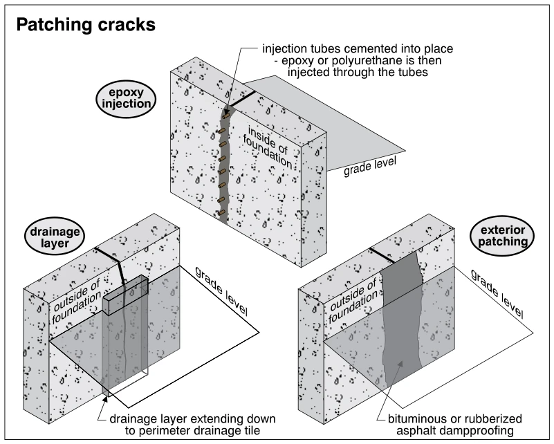
2080Patching cracks
· p. 371
The illustration shows three methods of treating cracks in concrete foundation walls. The interior treatment uses injection tubes cemented along the crack to inject epoxy or polyurethane. One exterior treatment places a drainage layer over the cracked area, extending down to perimeter drainage tile. The other exterior treatment covers the crack with bituminous or rubberized asphalt damproofing. Grade level is indicated in each view to show the relationship of the repairs to the below-grade wall.
 2081
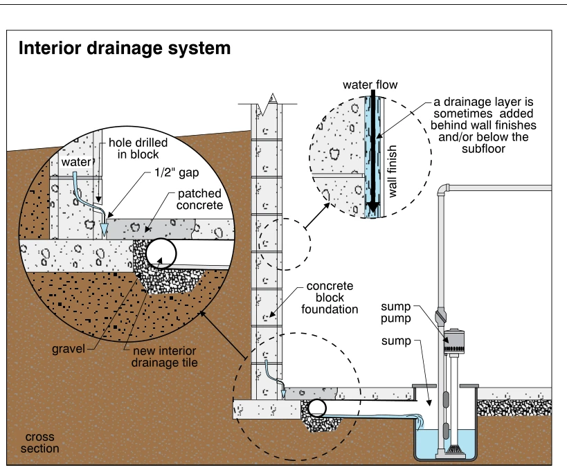
2081Interior drainage system
· p. 372
The cross section illustrates an interior basement drainage system along a concrete block foundation. An enlarged detail shows water draining through a hole drilled in the block and a 1/2-inch gap at the edge of the patched concrete floor into gravel surrounding new interior drainage tile. The drainage pipe conveys water to a sump containing a sump pump and an upward discharge pipe. A second enlarged detail shows an optional drainage layer behind the wall finish, with arrows indicating downward water flow; its annotation also notes possible placement below the subfloor.
 2082
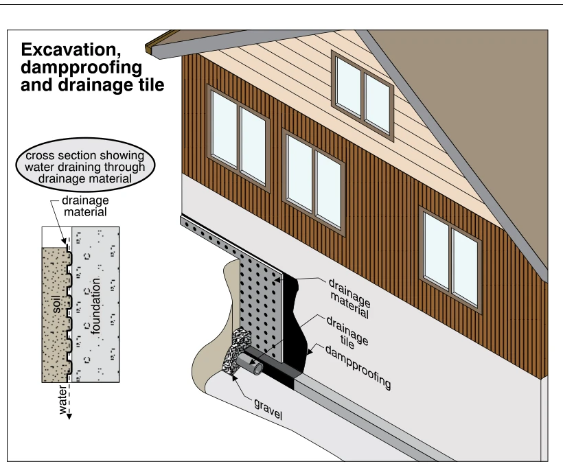
2082Excavation, dampproofing and drainage tile
· p. 372
The illustration shows an exterior excavation exposing a house foundation and its below-grade drainage assembly. A cutaway reveals drainage material over a dark dampproofing layer on the outside face of the foundation wall. Drainage tile and gravel are shown at the base of the wall beside the footing. An inset cross section shows drainage material separating soil from the foundation, with an arrow indicating downward water movement toward the foundation drainage system.
 2083
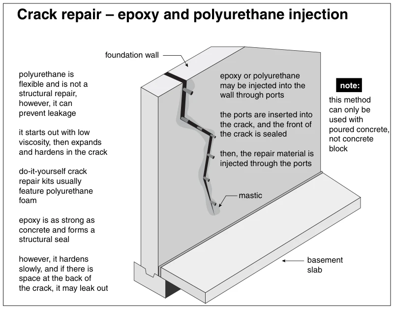
2083Crack repair – epoxy and polyurethane injection
· p. 372
The illustration shows a poured-concrete foundation wall with a jagged vertical crack above a basement slab. Injection ports are inserted along the crack, and mastic seals its exposed face before epoxy or polyurethane is injected through the ports. The annotations explain that polyurethane expands and hardens to prevent leakage but remains flexible and is not a structural repair. Epoxy forms a structural seal but hardens slowly and may escape if there is space behind the crack. A note limits this repair method to poured concrete rather than concrete block.
 2084
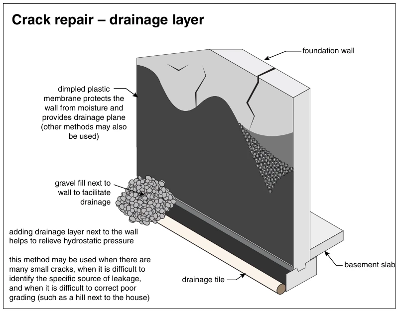
2084Crack repair – drainage layer
· p. 372
The illustration shows an exterior drainage layer installed against a cracked foundation wall, with a basement slab on the interior side. A cutaway exposes the dimples of a plastic membrane that protects the wall from moisture and provides a drainage plane. Gravel fill beside the wall facilitates drainage toward drainage tile at the base. The annotations explain that this approach relieves hydrostatic pressure and may be used for numerous small cracks, unidentified leakage sources, or grading problems that are difficult to correct.
 2085
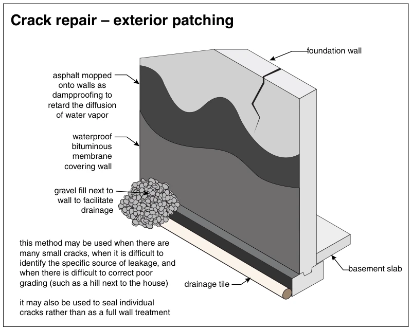
2085Crack repair – exterior patching
· p. 372
The illustration shows exterior treatment of a cracked foundation wall beside a basement slab. Cutaway layers identify asphalt dampproofing to retard water-vapor diffusion and a waterproof bituminous membrane covering the wall. Gravel fill alongside the wall facilitates drainage to drainage tile at the base. The annotations describe this treatment as an option for numerous small cracks, uncertain leakage sources, or difficult-to-correct grading, and note that it can also be applied to individual cracks.
 2086
2086Interior drainage system – different approaches
· p. 372
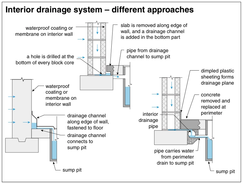
Three cross-sectional details illustrate different interior basement drainage arrangements that direct water to sump pits. The upper detail shows holes drilled at the bottom of concrete block cores, an interior waterproof coating or membrane, and a drainage channel installed in a removed strip of slab beside the wall. The lower-left detail shows an interior wall coating or membrane and a drainage channel fastened to the floor along the wall, with a connection to a sump pit. The right-hand detail shows dimpled plastic sheeting forming a drainage plane against a block wall, leading to an interior drainage pipe below the slab perimeter. Concrete is removed and replaced above this perimeter drain, and a connecting pipe carries water to the sump pit; blue arrows indicate water movement.
 2087
2087Basement leakage clues – efflorescence
· p. 373
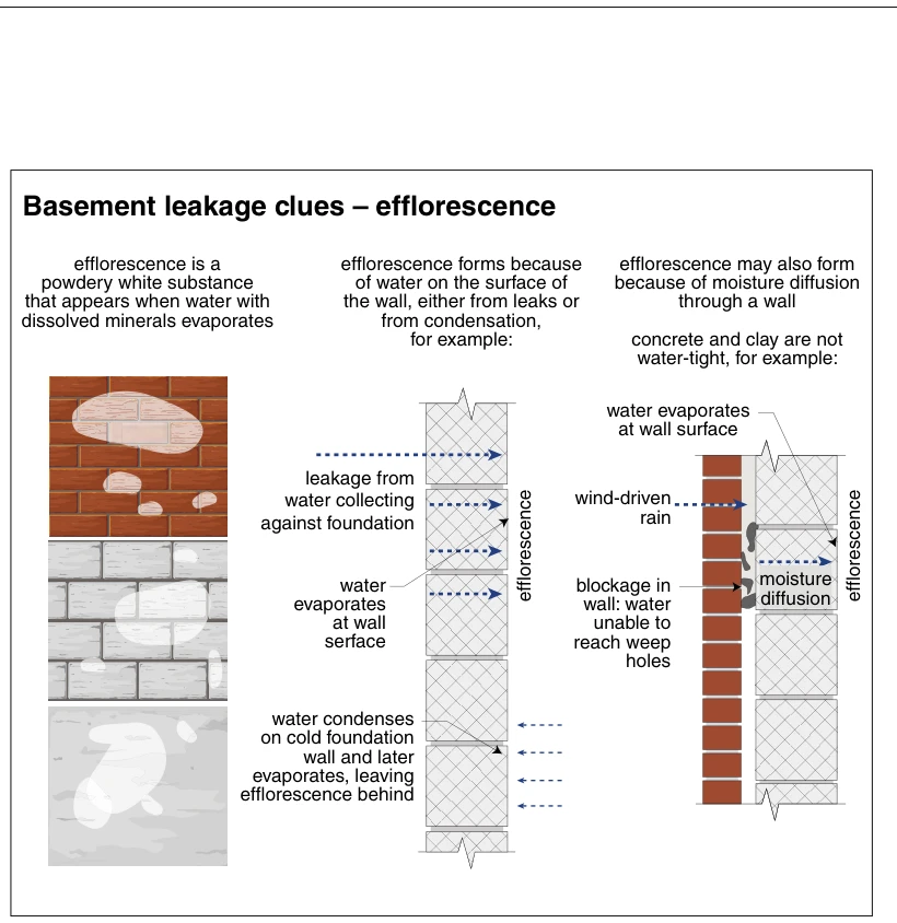
The illustration shows powdery white efflorescence deposits on brick, masonry block, and concrete wall surfaces. A foundation-wall section depicts water collecting against the foundation and passing through it, then evaporating at the interior surface and leaving mineral deposits. The same section illustrates condensation on a cold foundation wall followed by evaporation and efflorescence. A second wall section shows wind-driven rain entering a brick-faced masonry assembly, with a cavity blockage preventing water from reaching weep holes. Arrows show moisture diffusion through the backing wall and evaporation at its surface, illustrating that efflorescence can arise from several moisture mechanisms.
 2088
2088Basement leakage clues – rot, stains or water marks
· p. 373
A cutaway basement shows wood floor joists and a sill above a masonry foundation wall, an adjacent finished wall, and carpet partially lifted from a floor slab. Callouts identify joist ends and the sill as locations to check for rot associated with poor ground clearance. Shaded areas indicate stains on the masonry wall, at a finished-wall corner, and on the carpet or slab. Another annotation advises checking for water marks along studs while noting that thermal bridging can also cause stud-line staining in an insulated wall. Water-damaged boxes and raised storage are illustrated as additional basement leakage clues.
 2089
2089Basement leakage clues – rust
· p. 373
A cutaway basement shows wood floor joists supported by a steel I-beam and a metal column above a concrete floor slab. Exposed concrete-block foundation wall, a drywall-finished wall, and partially pulled-back carpet reveal locations to check for rust as evidence of basement moisture or leakage. Callouts identify beams near exterior walls, drywall fasteners, carpet tacks and tack strips, column bases, and metal fasteners in the foundation wall. Orange markings highlight corrosion or rust staining at several of these locations.
 2090
2090Basement leakage clues – crumbling plaster, drywall or masonry
· p. 373
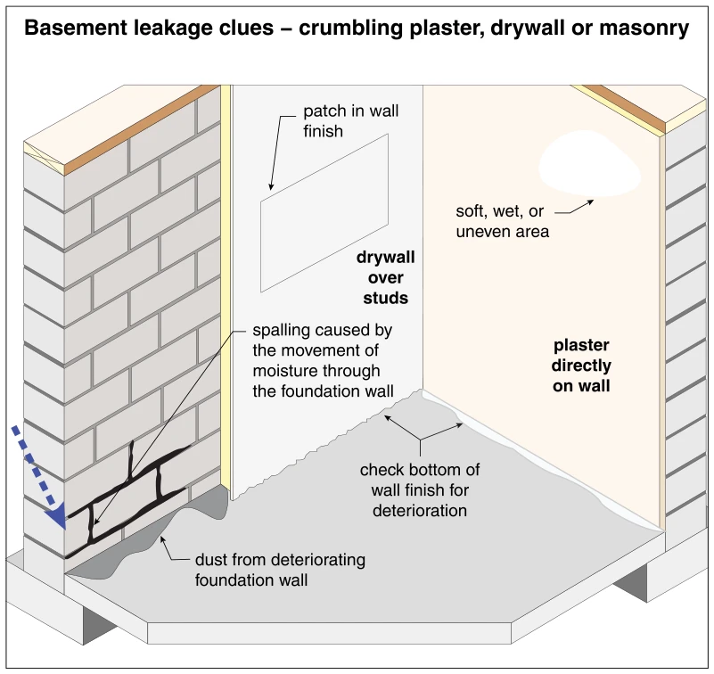
The illustration shows a basement corner with exposed masonry foundation wall, drywall over studs, and plaster applied directly to the wall. Spalling near the bottom of the exposed masonry is attributed to moisture moving through the foundation wall, with deteriorated material collecting on the floor. The drywall has a rectangular patch and a ragged, deteriorated lower edge. A marked area on the plaster indicates a soft, wet, or uneven surface. Arrows emphasize checking the bottoms of wall finishes for deterioration as a clue to basement leakage.