
03Electrical
135 illustrations · printed pages 83-108
Service Drop And Service Entrance ·The Basics of Electricityp. 84
 0500
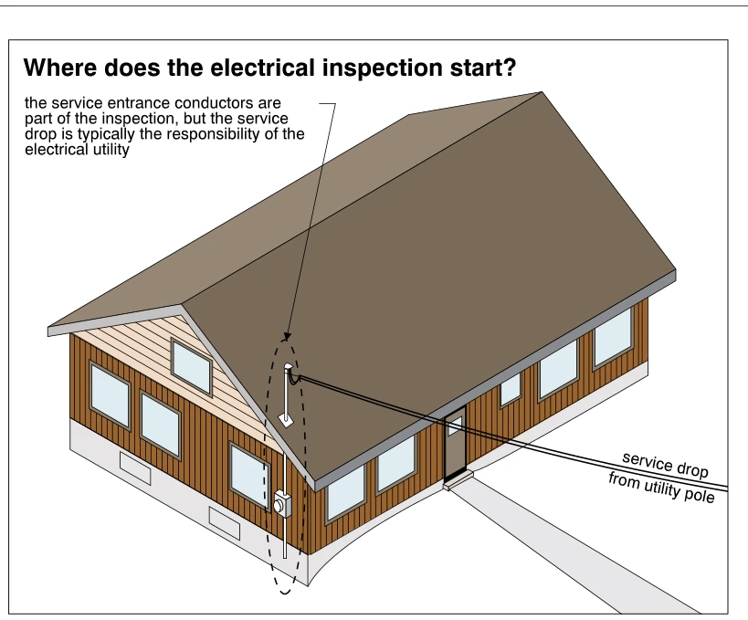
0500Where does the electrical inspection start?
· p. 84
The illustration shows an overhead electrical service supplying a house, with the service drop approaching a roof-mounted service mast and weatherhead. A dashed outline highlights the service entrance path from the roof down to the exterior electric meter and conduit below it. The annotation identifies the service entrance conductors as part of the inspection, while the service drop is typically the electrical utility's responsibility. No specific electrical defect is depicted.
 0501
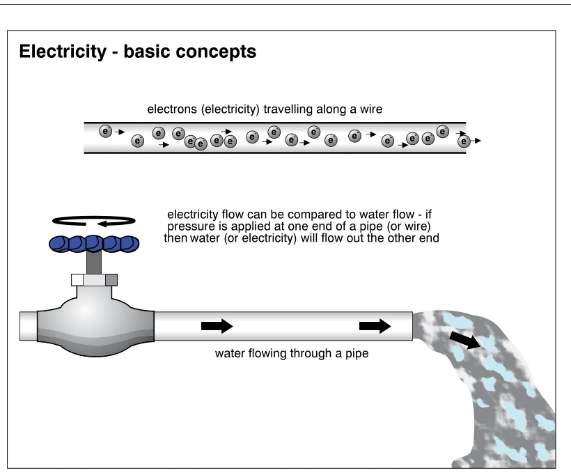
0501Electricity - basic concepts
· p. 84
The illustration explains electrical flow using an analogy to water flowing through a pipe. The upper diagram shows electrons within a wire, with arrows indicating travel to the right. The lower diagram shows a handwheel-operated valve connected to a horizontal pipe, with water discharging from its open right end. Arrows indicate water flow through the pipe, while an arrow above the handwheel indicates rotation. The annotation compares pressure-driven water flow with electricity flowing along a wire; no installation defect is depicted.
 0502
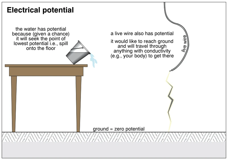
0502Electrical potential
· p. 84
The illustration explains electrical potential using an analogy between water spilling from a tipped pail on a table and electricity flowing from a live wire toward ground. On the left, water falls from the elevated pail toward the floor. On the right, a hanging live wire ends above the ground, with a jagged line symbolizing an electrical path toward it. The ground is labeled as zero potential, and the text warns that conductive objects, including a person's body, can provide a path to ground.
 0503
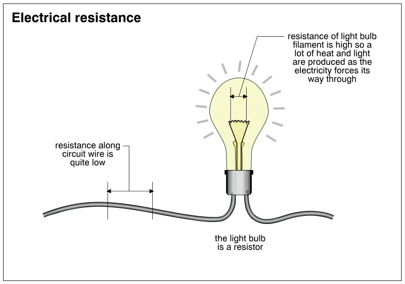
0503Electrical resistance
· p. 84
The illustration shows an illuminated incandescent light bulb connected to circuit wires at its base. The bulb's internal filament and supporting leads are visible. An annotation contrasts the relatively low resistance along the circuit wire with the high resistance of the filament, which produces heat and light as current passes through it. The light bulb is identified as a resistor; no wiring defect or improper installation is depicted.
 0504
0504Current flow = amperage
· p. 84
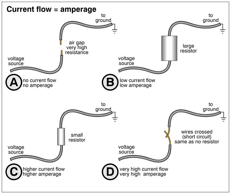
Four schematic examples illustrate how resistance affects current flow, or amperage, along a path from a voltage source to ground. Example A shows an air gap with very high resistance and no current flow. Examples B and C show a large resistor with low current flow and a small resistor with higher current flow, respectively. Example D shows crossed exposed wires forming a short circuit, labeled as equivalent to no resistor and producing very high current flow.
 0505
0505120/240 volts
· p. 84
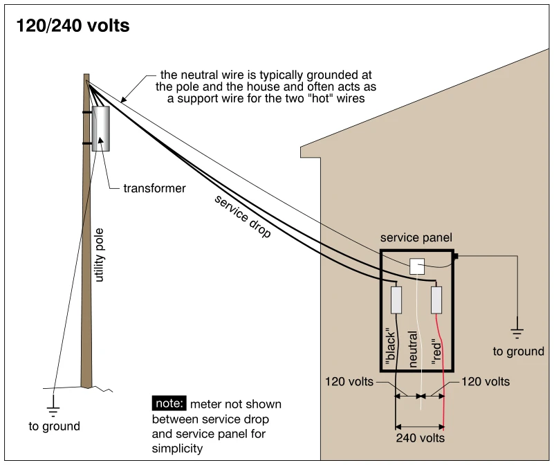
The illustration shows a pole-mounted transformer supplying a house service panel through an overhead service drop. Two hot conductors, labeled "black" and "red," and a neutral conductor form the 120/240-volt supply. Dimension arrows indicate 120 volts between each hot conductor and neutral, and 240 volts between the two hot conductors. Ground connections are shown at the utility pole and house, and an annotation explains that the neutral often supports the two hot wires. A note states that the meter between the service drop and panel is omitted for simplicity.
 0506
0506Color coding for typical 120 volt circuit
· p. 85
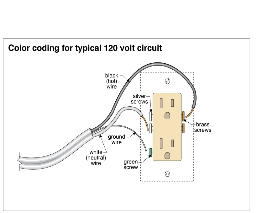
The illustration shows a sheathed cable with three conductors fanned out beside a duplex grounding receptacle. The black hot wire is positioned at the brass terminal screws, while the white neutral wire is positioned at the silver terminal screws. The bare ground wire is directed toward the green grounding screw. The diagram identifies the conductor colors and corresponding receptacle terminals for a typical 120-volt circuit.
 0507
0507A simple electrical circuit
· p. 85
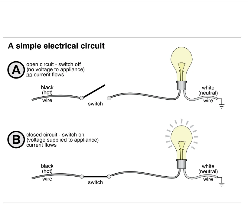
Two diagrams compare an open and a closed electrical circuit supplying a light bulb. In diagram A, the switch interrupts the black hot conductor, and the bulb is unlit; the annotation states that no current flows. In diagram B, the switch connects the hot conductor, completing the circuit and illuminating the bulb. Both diagrams show a white neutral conductor leaving the bulb and terminating at a ground symbol. The illustration explains switch operation rather than depicting an installation defect.
 0508
0508Short circuit
· p. 85
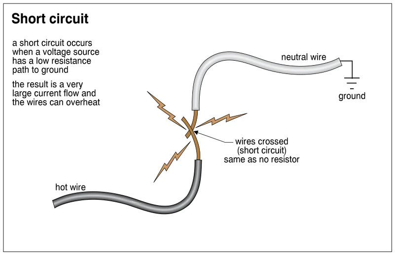
The diagram shows a black-insulated hot wire and a white-insulated neutral wire with exposed ends crossing and touching. The neutral wire connects to a ground symbol at the upper right. Lightning-like marks highlight the short-circuit contact between the exposed conductors. The annotations explain that this low-resistance path permits very large current flow and can cause the wires to overheat.
 0509
0509Fuses and breakers
· p. 85
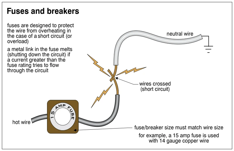
The diagram shows a hot wire passing through a 15-amp fuse and contacting a neutral wire at an exposed crossing marked as a short circuit. Lightning-shaped symbols emphasize the fault, and the neutral wire terminates at a ground symbol. Annotations explain that a fuse's metal link melts when current exceeds its rating, opening the circuit to protect wiring from overheating during a short circuit or overload. The illustration states that fuse or breaker size must match wire size, giving a 15-amp fuse with 14-gauge copper wire as an example.
 0510
0510Fuses provide protection against:
· p. 85
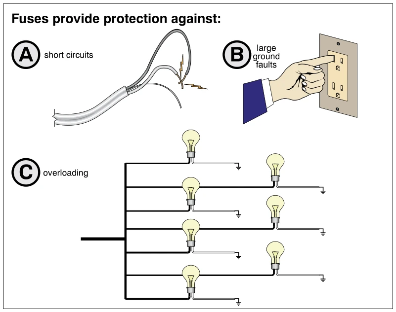
The illustration identifies three electrical conditions against which fuses provide protection. Panel A shows exposed cable conductors with sparks indicating a short circuit. Panel B shows a person touching a receptacle, illustrating a large ground fault. Panel C depicts multiple light bulbs connected to a common supply conductor to illustrate overloading. The figure explains the purpose of fuses rather than showing a fuse or its installation.
 0511
0511Household wiring is done in parallel
· p. 85
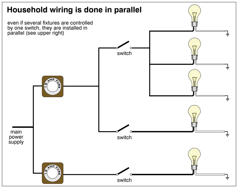
This schematic depicts a main power supply feeding two fused lighting circuits, each marked with a 15-amp fuse. The upper circuit splits into two switched paths: one supplies three lamps connected in parallel, and the other supplies a single lamp. The lower circuit supplies one lamp through a separate switch. All three switches are drawn open, and each lamp has a return line ending in a ground symbol. The illustration emphasizes that multiple fixtures controlled by a single switch are still wired in parallel.
Service Drop And Service Entrance ·Service Dropsp. 86
 0512
0512Damaged wire
· p. 86
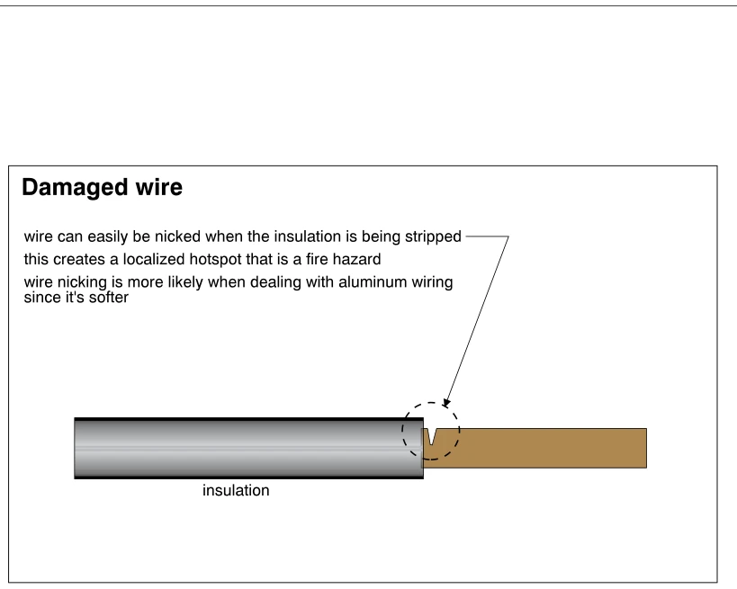
The illustration shows an insulated electrical wire with insulation stripped from one end to expose the conductor. A deep nick in the conductor immediately beside the remaining insulation is highlighted by a dashed circle and an arrow. The annotations explain that stripping insulation can nick the wire, creating a localized hotspot and fire hazard. They also note that softer aluminum wiring is more susceptible to nicking.
 0513
0513Service drop
· p. 86
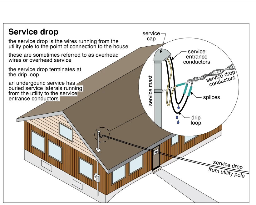
The illustration shows an overhead electrical service drop connecting to a service mast projecting above a house roof. An enlarged detail shows service entrance conductors exiting the service cap and joining the service drop conductors at splices. The conductors form downward drip loops, with water droplets illustrating drainage below the connections and cap. The house view also shows the exterior meter and service raceway. Printed notes define the service drop and distinguish it from buried service laterals used for underground service.
 0514
0514Underground electrical service
· p. 86
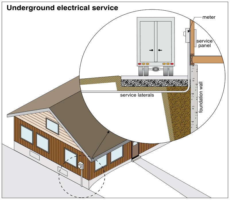
The illustration shows a house supplied by underground electrical service, with an enlarged section at the service entrance. Service laterals run below grade beneath a driveway and curve upward along the exterior of the foundation wall to the meter. A service panel is shown on the interior side of the wall near the meter. The cutaway includes a vehicle on the driveway, the driveway base, surrounding soil, and the house foundation and floor framing. No defect or improper installation is specifically identified.
 0515
0515Service drop clearances (United States)
· p. 86
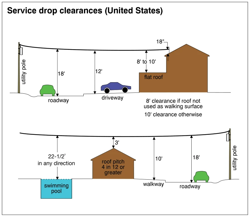
Two diagrams illustrate overhead electrical service drop clearances above residential roofs, roadways, driveways, walkways, and a swimming pool. The upper diagram shows 18 feet above a roadway, 12 feet above a driveway, and 8 to 10 feet above a flat roof, with a note specifying 8 feet if the roof is not used as a walking surface and 10 feet otherwise. An 18-inch dimension is shown at the service attachment near the house roof edge. The lower diagram shows 22-1/2 feet in any direction from a swimming pool, 3 feet above a roof with a pitch of 4 in 12 or greater, 10 feet above a walkway, and 18 feet above a roadway.
 0516
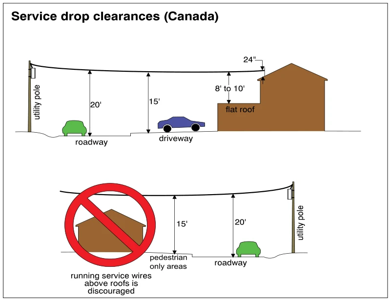
0516Service drop clearances (Canada)
· p. 86
The illustration shows overhead electrical service drop clearances in Canada using two elevation diagrams. The upper diagram shows wires extending from a utility pole toward a house, with clearances labeled 20 feet above a roadway, 15 feet above a driveway, and 8 to 10 feet above a flat roof. A separate 24-inch vertical dimension is shown between the wire and the roof edge near the house connection. The lower diagram labels clearances of 15 feet above pedestrian-only areas and 20 feet above a roadway. A red prohibition symbol over a house beneath the wires emphasizes that running service wires above roofs is discouraged.
 0517
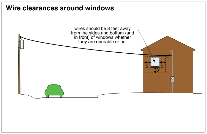
0517Wire clearances around windows
· p. 86
The illustration shows an overhead electrical service drop running from a utility pole to a house, with a window near the service entrance. A service mast and meter are shown on the exterior wall to the right of the window. Dashed lines and dimension arrows mark 3-foot clearances at both sides and below the window. The annotation specifies that wires should also remain 3 feet in front of windows, whether the windows are operable or not.
Service Drop And Service Entrance ·Service Entrance Wiresp. 87
 0518
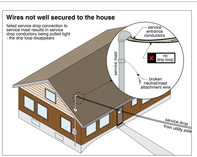
0518Wires not well secured to the house
· p. 87
The illustration shows an overhead electrical service drop approaching a house and connecting to a roof-mounted service mast. An enlarged detail shows a broken neutral/mast attachment wire at the mast. The failed attachment allows the service drop conductors to pull tight, eliminating the drip loop at the service entrance conductors. A red X identifies the missing drip loop as an improper condition.
 0519
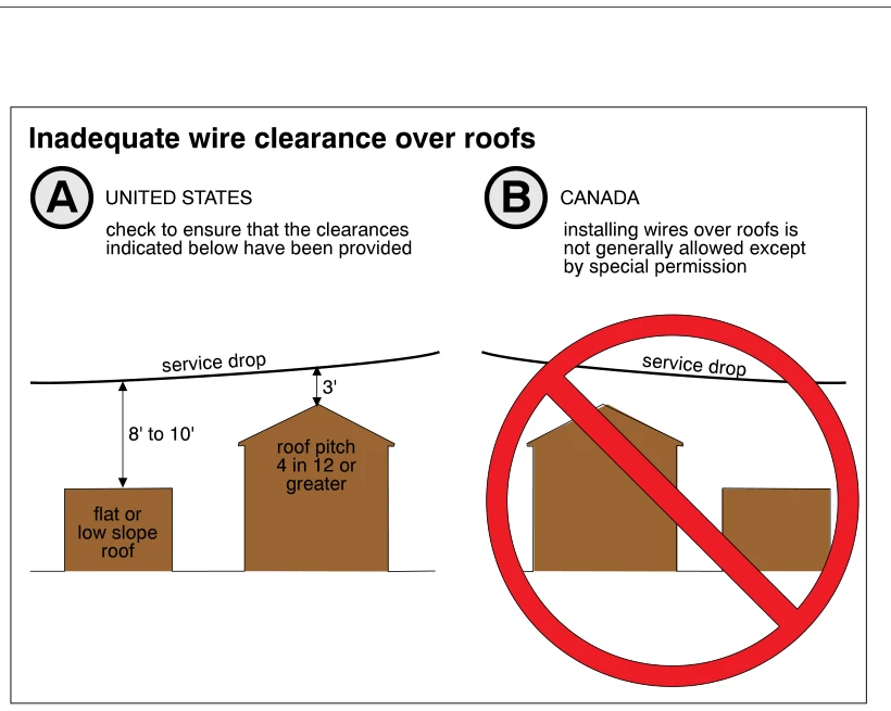
0519Inadequate wire clearance over roofs
· p. 87
The illustration compares overhead electrical service-drop clearance guidance for the United States and Canada. The United States panel shows a service drop passing above a flat or low-slope roof and a pitched roof, with vertical clearance dimensions of 8 to 10 feet and 3 feet, respectively. The pitched roof is labeled as having a pitch of 4 in 12 or greater, and an annotation directs the reader to verify the indicated clearances. The Canada panel shows wires above two roofs overlaid with a red prohibition symbol and states that installing wires over roofs is generally not allowed except by special permission.
 0520
0520Drip loop
· p. 87
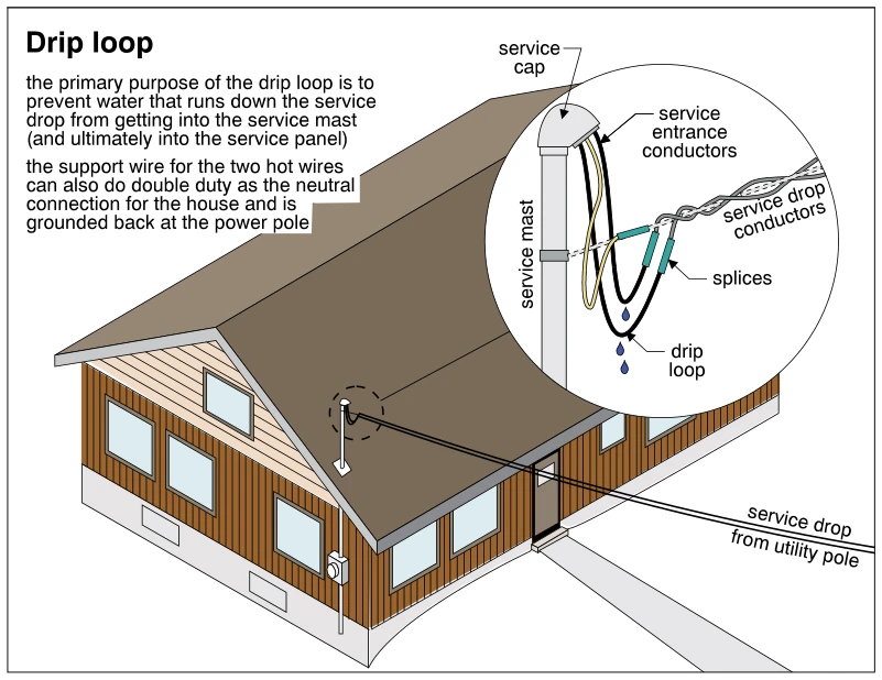
The illustration shows an overhead electrical service drop connecting to a service mast at a house, with an enlarged detail of the conductor connections. Service entrance conductors emerge from the service cap and loop downward before joining the service drop conductors at splices. Water droplets beneath the loops illustrate how the low points shed water before it can enter the mast and ultimately the service panel. An annotation explains that the support wire for the two hot wires can also serve as the house neutral and is grounded at the power pole.
 0521
0521Service entrance wires
· p. 87
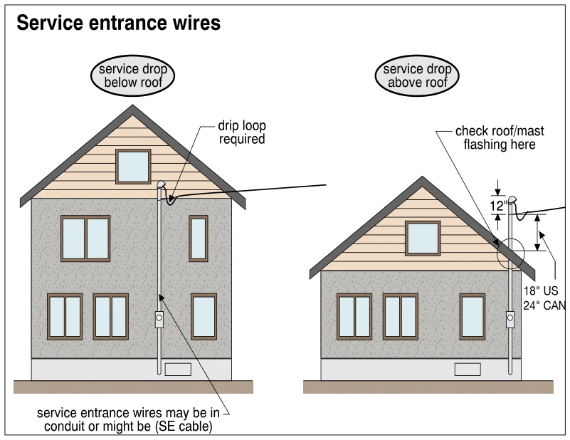
Two house elevations illustrate overhead electrical service drops entering below the roof and above the roof. The left arrangement has a wall-mounted service entrance with a weatherhead and a required drip loop, with service entrance wires running down to a meter in conduit or as SE cable. The right arrangement uses a service mast extending through the roof, and a callout identifies the roof/mast flashing as an inspection location. Dimension arrows at the above-roof connection show 12 inches and roof-clearance annotations of 18 inches for the US and 24 inches for Canada.
 0522
0522Drip loop
· p. 87
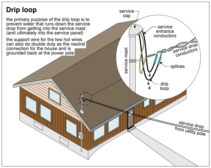
The illustration shows an overhead electrical service drop connecting to a service mast on a house, with a magnified detail of the service cap and conductor connections. Service entrance conductors exit the cap and curve downward into drip loops before connecting to the service drop conductors at splices. Water droplets beneath the loops illustrate how water sheds below the cap rather than running into the mast and ultimately the service panel. An annotation explains that the support wire for the two hot wires can also serve as the house neutral and is grounded at the power pole. A meter is shown on the exterior wall beneath the mast.
 0523
0523Using service entrance cable
· p. 87
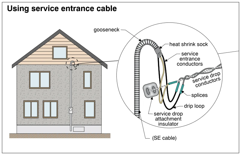
The illustration shows overhead electrical service connected to service entrance cable running down the exterior wall of a house to a meter. An enlarged detail shows the upper end of the SE cable bent into a downward-facing gooseneck, with a heat shrink sock at the conductor exit. The service entrance conductors form drip loops below their splices to the service drop conductors. A service drop attachment insulator supports the incoming overhead service at the wall.
Service Drop And Service Entrance ·Service Sizep. 88
 0524
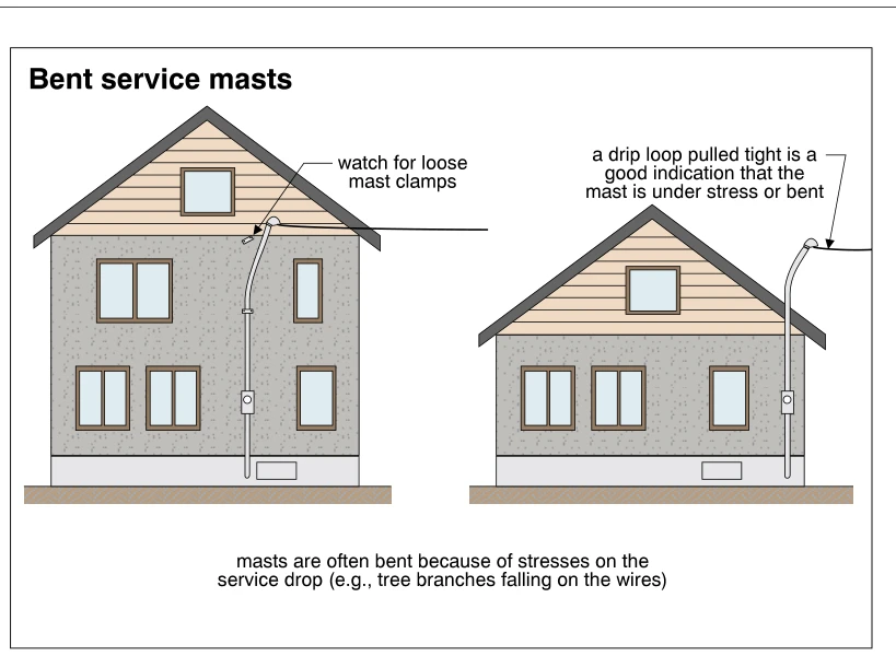
0524Bent service masts
· p. 88
Two house elevations illustrate bent electrical service masts carrying overhead service-drop connections. Each mast runs up an exterior wall from a meter enclosure and bends near its upper end toward the service wires. The left example calls attention to loose mast clamps, while the right identifies a drip loop pulled tight as evidence of stress or bending. The bottom annotation explains that loads on service-drop wires, such as falling tree branches, often cause mast bending.
 0525
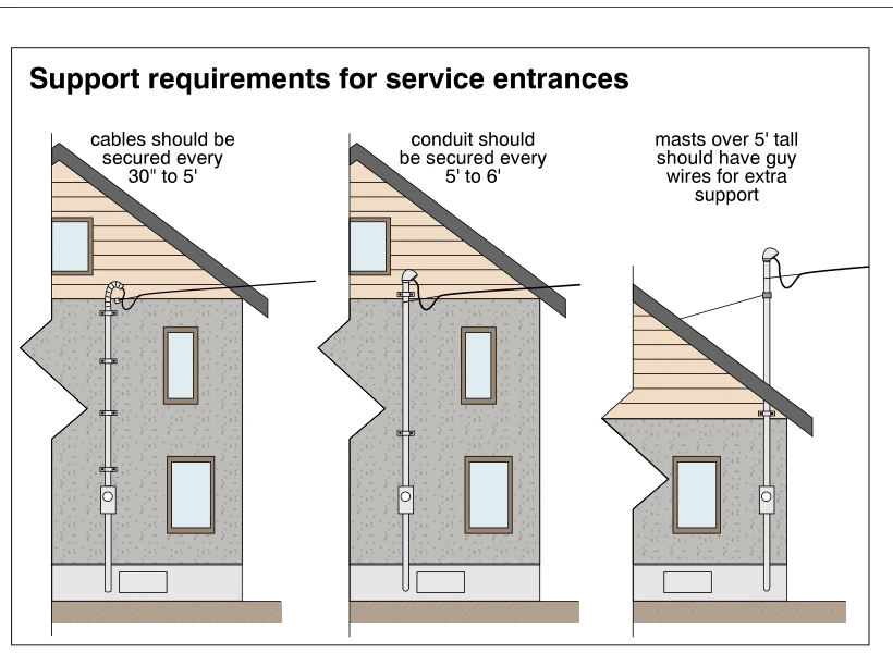
0525Support requirements for service entrances
· p. 88
Three house-elevation details illustrate support requirements for electrical service entrances. The left detail shows a wall-mounted service entrance cable secured with multiple straps between the weatherhead and meter, with fastening intervals labeled as 30 inches to 5 feet. The center detail shows service entrance conduit strapped to the wall, with support intervals labeled as 5 to 6 feet. The right detail shows a service mast extending above the roof, supported by wall attachments and a guy wire running back toward the roof. Its annotation calls for extra guy-wire support for masts over 5 feet tall.
 0526
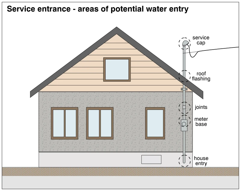
0526Service entrance - areas of potential water entry
· p. 88
The illustration shows an overhead electrical service entrance on the exterior of a gable-roofed house. A vertical service mast extends through the roof to a service cap, where an overhead conductor forms a downward loop. The raceway runs down the exterior wall through a meter base and continues to a house entry near the bottom of the foundation wall. Dashed circles identify the service cap, roof flashing, raceway joints, meter base, and house entry as potential water-entry locations. No actual leakage or damaged components are depicted.
 0527
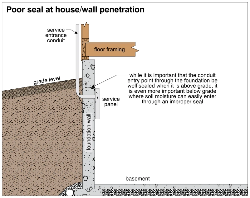
0527Poor seal at house/wall penetration
· p. 88
The illustration shows a section through a basement foundation wall with exterior soil and wood floor framing above. A service entrance conduit descends outside the house, bends inward, and passes through the foundation below grade to a service panel inside. A callout identifies the improperly sealed conduit penetration as a route for soil moisture to enter. The annotation emphasizes that sealing is important above grade and even more critical at below-grade penetrations.
 0528
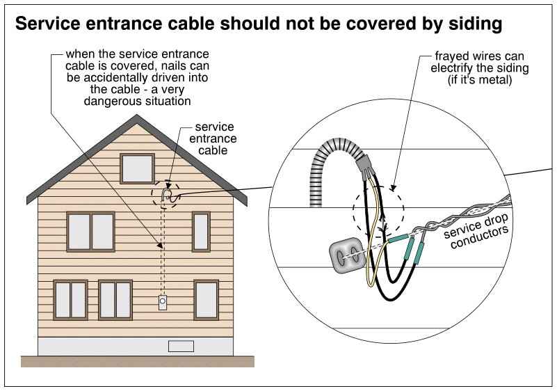
0528Service entrance cable should not be covered by siding
· p. 88
The illustration shows a house with a service entrance cable concealed behind horizontal exterior siding, its route indicated by dashed lines down to a small electrical enclosure. An enlarged detail shows the overhead service drop conductors, their attachment to the wall, and connections to the service entrance wires. Frayed wires are highlighted near the service entrance head. The annotations warn that siding nails can penetrate a concealed cable and that damaged wires can energize metal siding.
 0529
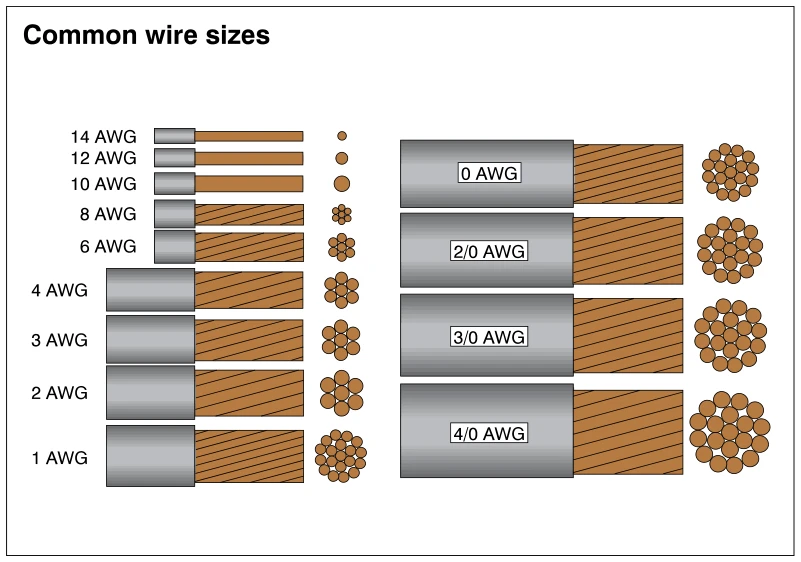
0529Common wire sizes
· p. 88
The illustration presents common electrical conductor sizes from 14 AWG through 4/0 AWG, with side views of partially stripped wires and corresponding conductor cross-sections. The 14, 12, and 10 AWG examples show solid conductors, while the larger sizes show bundles of strands. Gray insulation surrounds the copper-colored conductors in the side views. The drawings illustrate increasing conductor diameter as the gauge number decreases, followed by progressively larger aught sizes. No defects or installation practices are depicted.
Service Box, Grounding And Panels ·Service Boxesp. 89
 0530
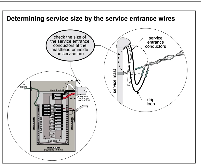
0530Determining service size by the service entrance wires
· p. 89
The illustration shows two locations for checking service entrance conductor size to help determine electrical service capacity: at the masthead and inside the service box. The exterior detail shows conductors emerging from a weatherhead on a service mast, forming drip loops, and connecting to overhead service wires. The interior detail shows service entrance conductors entering a breaker panel and connecting at the main breaker. Branch circuit breakers, bus bars, a neutral bus bar, a grounding terminal, and a conductor leading to ground are also identified. Dashed circles highlight the service entrance conductors at both inspection locations; no defect is depicted.
 0531
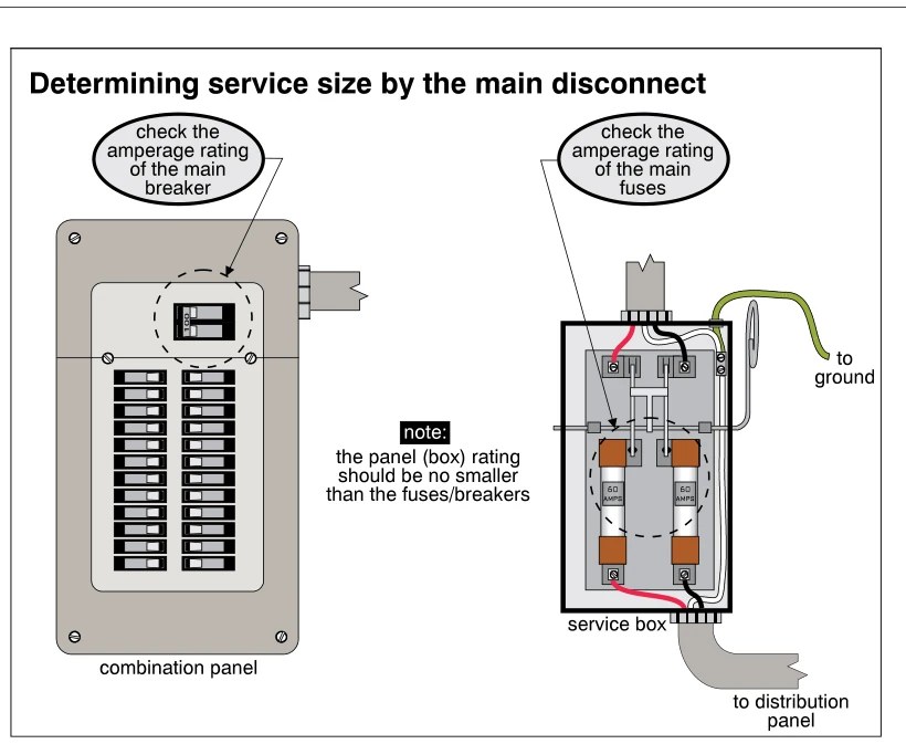
0531Determining service size by the main disconnect
· p. 89
The illustration shows two ways to determine electrical service size by checking the amperage rating of the main disconnect. On the left, a combination panel contains a main breaker above two columns of branch-circuit breakers, with the main breaker circled for emphasis. On the right, an open service box contains two cartridge fuses marked 60 AMPS, with conductors leading to a distribution panel and a grounding connection labeled. A central note states that the panel or box rating should be no smaller than the fuse or breaker rating.
 0532
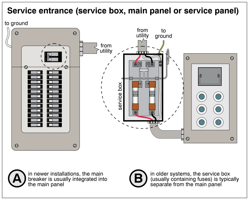
0532Service entrance (service box, main panel or service panel)
· p. 89
The illustration compares two residential electrical service equipment arrangements. Arrangement A shows a main circuit breaker integrated into the upper portion of a panel containing two columns of branch-circuit breakers, with utility supply and grounding connections indicated. Arrangement B shows an open, separate service box containing a disconnect mechanism and two cartridge fuses marked 60 AMPS. Conductors run from this service box through a conduit to an adjacent panel with six circular fuse positions. Dashed circles emphasize the main disconnect locations; no defects are identified.
 0533
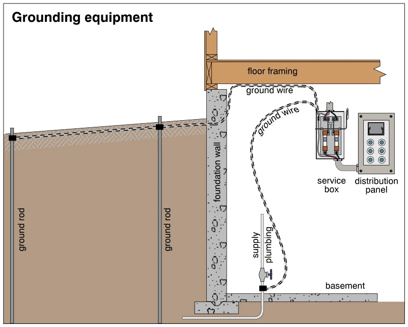
0533Grounding equipment
· p. 89
The illustration shows an electrical service box and adjacent distribution panel in a basement beside a foundation wall. A ground wire runs from the service box beneath the floor framing, through the foundation wall, and to two exterior ground rods driven into the soil. Another ground wire connects the service box to the metal supply plumbing near its entry through the basement floor. The service box is shown open, exposing internal electrical components, and is connected to the distribution panel by a short conduit. No grounding defects are identified.
 0534
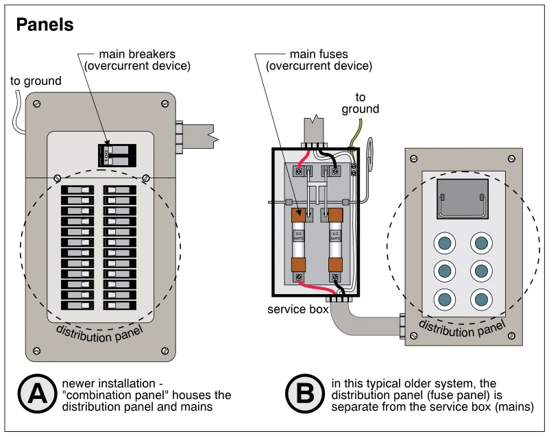
0534Panels
· p. 89
The illustration compares two residential electrical service and distribution arrangements. Arrangement A shows a newer combination panel with main circuit breakers above two columns of branch-circuit breakers, all in one enclosure. Arrangement B shows an older service box containing main cartridge fuses and a disconnect mechanism, connected by conduit to a separate fuse distribution panel. Grounding connections are indicated at the combination panel and the separate service box. Dashed outlines identify the distribution-panel portions of each arrangement; no defects are indicated.
 0535
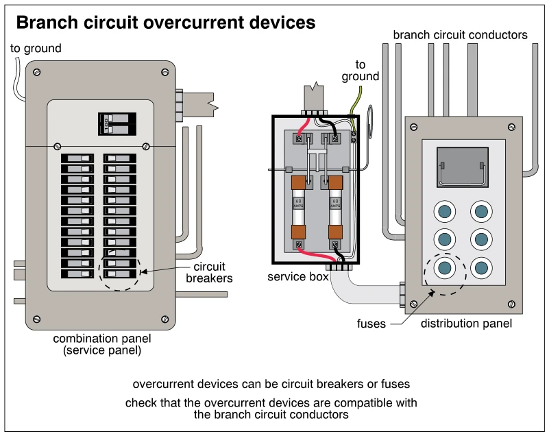
0535Branch circuit overcurrent devices
· p. 89
The illustration shows two arrangements for branch circuit overcurrent protection. On the left, a combination service panel contains a main breaker above two columns of branch circuit breakers. On the right, a separate service box containing two cartridge fuses is connected by conduit to a distribution panel with six round fuses. Ground connections and outgoing branch circuit conductor routes are indicated. The annotation instructs inspectors to check that the overcurrent devices are compatible with the branch circuit conductors; no specific defect is depicted.
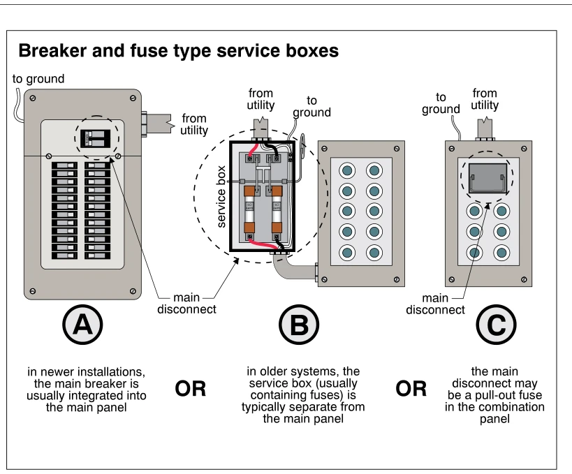 0536
0536Breaker and fuse type service boxes
· p. 90
The illustration compares three electrical service-box arrangements, identifying utility supply entries, grounding connections, and main disconnects. Arrangement A shows a main circuit breaker integrated into a panel with two columns of branch circuit breakers. Arrangement B shows a separate service box containing two cartridge fuses, connected by a raceway to a panel containing screw-in fuses. Arrangement C shows a combination fuse panel with a pull-out main disconnect above the branch circuit fuses. Dashed outlines emphasize the main disconnect or service-box locations; no defects are indicated.
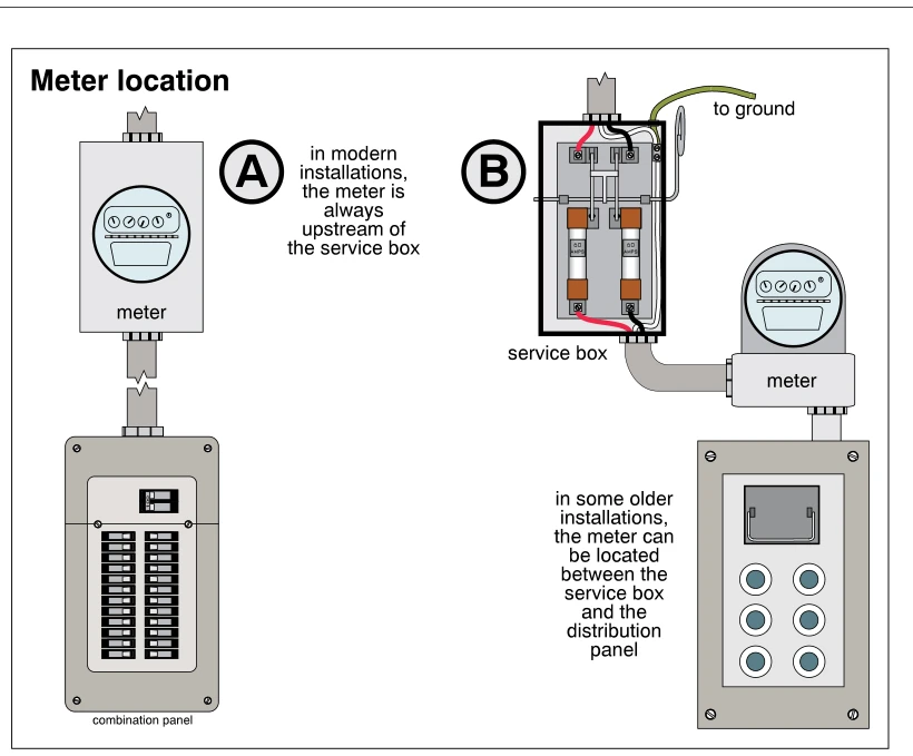 0537
0537Meter location
· p. 90
The illustration compares electric meter locations in modern and some older residential service arrangements. Arrangement A shows a meter upstream of a combination panel containing a main breaker and branch-circuit breakers. Arrangement B shows an open fused service box upstream of the meter, with the meter connected onward to a separate distribution panel containing round fuse positions. The older arrangement also shows a grounding conductor leaving the service box, labeled "to ground." Neither arrangement is marked as defective.
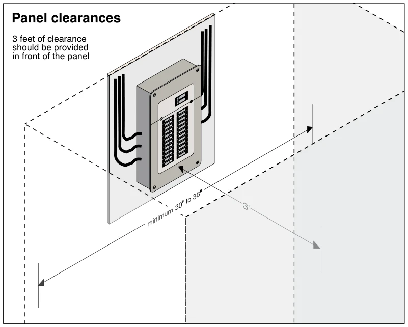 0538
0538Panel clearances
· p. 90
The illustration shows a wall-mounted electrical service panel with a main breaker, two columns of branch-circuit breakers, and wiring entering from both sides. Dashed lines outline the unobstructed working space in front of the panel. A dimension arrow specifies 3 feet of clearance in front of the panel, while another marks a minimum working-space width of 30 to 36 inches. No obstructions or clearance defects are depicted.
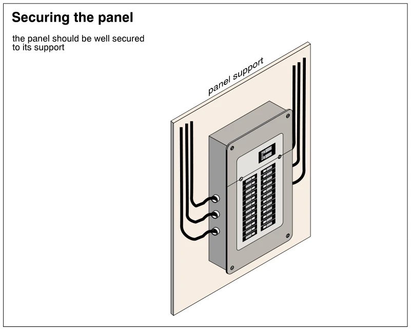 0539
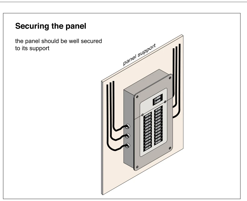
0539Securing the panel
· p. 90
The illustration shows an electrical panel mounted on a flat support board. The panel has a front cover with an upper breaker and two vertical banks of smaller circuit breakers. Multiple electrical cables run along the support and enter the sides of the enclosure. The annotation emphasizes that the panel should be well secured to its support; the attachment method behind the enclosure is not shown.
 0540
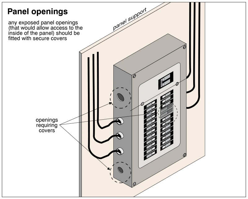
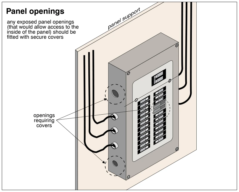
0540Panel openings
· p. 90
An electrical panel is mounted on a support board, with cables entering its enclosure from both sides. The front cover exposes two vertical rows of circuit breakers and a larger breaker above them. Dashed circles and arrows identify uncovered circular openings in the enclosure side and unused breaker openings in the front. The annotation states that exposed openings allowing access to the panel interior should be fitted with secure covers.
 0541
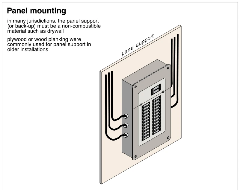
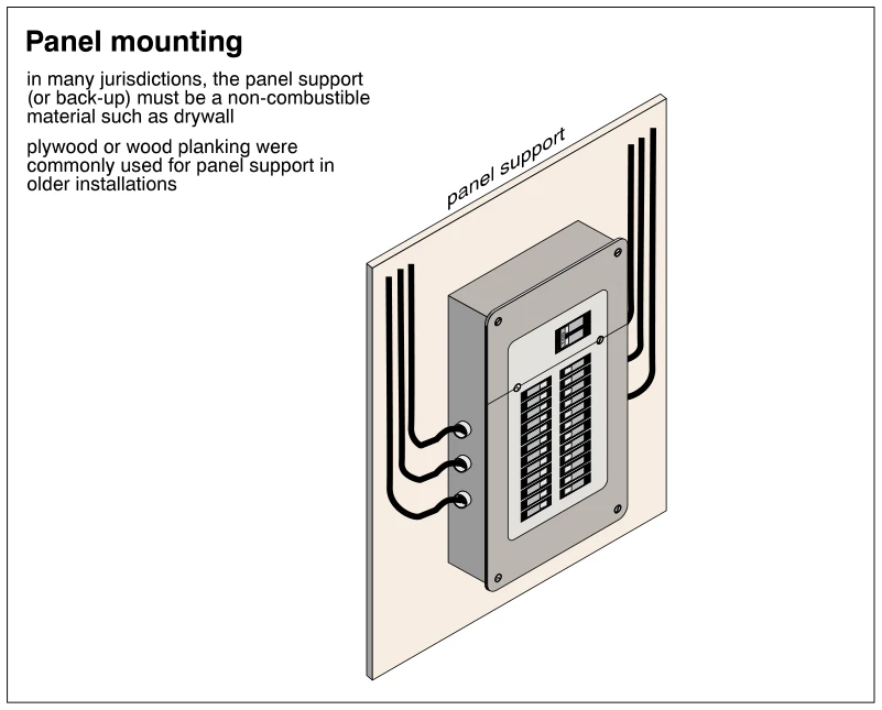
0541Panel mounting
· p. 90
The illustration shows an electrical circuit-breaker panel surface-mounted on a larger backing board identified as the panel support. Cables run vertically along both sides of the backing and curve into the sides of the panel enclosure. The panel face shows a main breaker above two columns of branch-circuit breakers. Annotations explain that many jurisdictions require non-combustible backing, such as drywall, and that plywood or wood planking commonly supported panels in older installations. The backing material in the drawing is not specifically identified.
Service Box, Grounding And Panels ·System Groundingp. 91
 0542
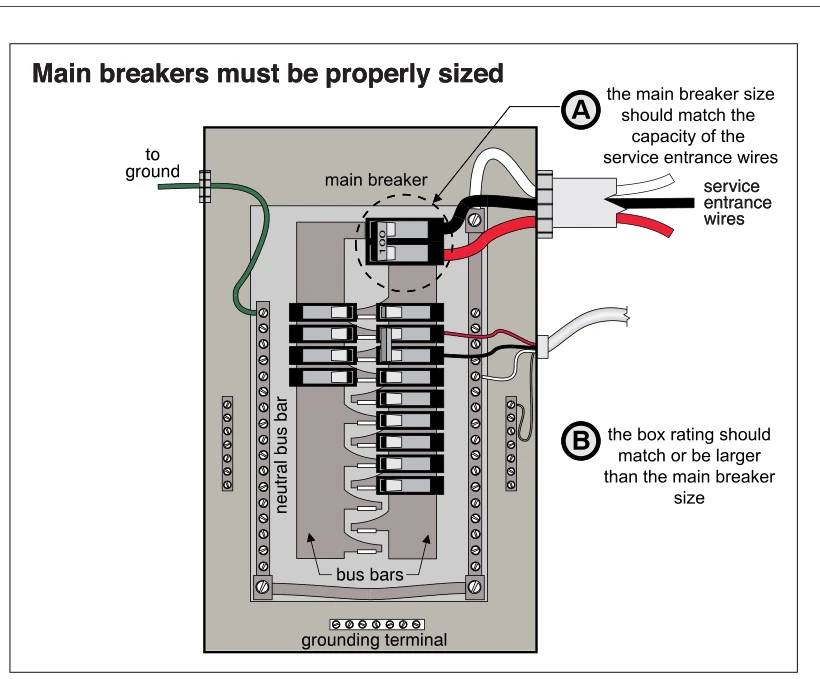
0542Main breakers must be properly sized
· p. 91
The illustration shows an electrical service panel with its cover removed, exposing a main breaker, branch circuit breakers, bus bars, neutral bus bar, and grounding terminal. Service entrance wires enter at the upper right, with the red and black conductors connected to the main breaker. A green conductor runs from the neutral bus bar toward ground. Annotations explain that the main breaker rating should match the capacity of the service entrance wires and that the panel box rating should equal or exceed the main breaker rating.
 0543
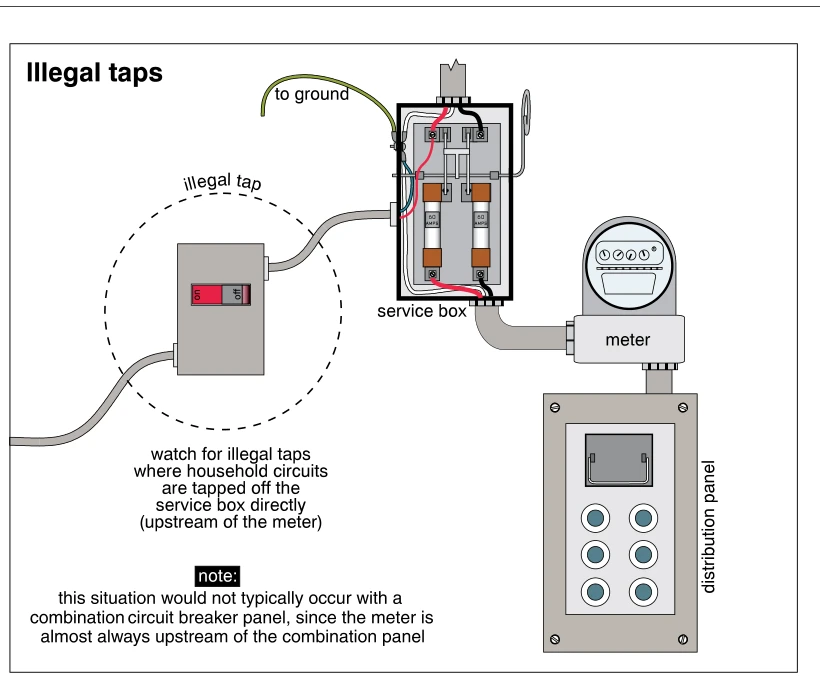
0543Illegal taps
· p. 91
The illustration shows an open fused service box connected by conduit to an electric meter, which in turn connects to a distribution panel. A grounding conductor extends from the service box toward ground. A separate circuit runs from the service box to a switch enclosure at the left, highlighted by a dashed circle as an illegal tap. This household circuit connection is upstream of the meter, bypassing metering. A note distinguishes this arrangement from a combination circuit breaker panel, where the meter is almost always upstream of the panel.
 0544
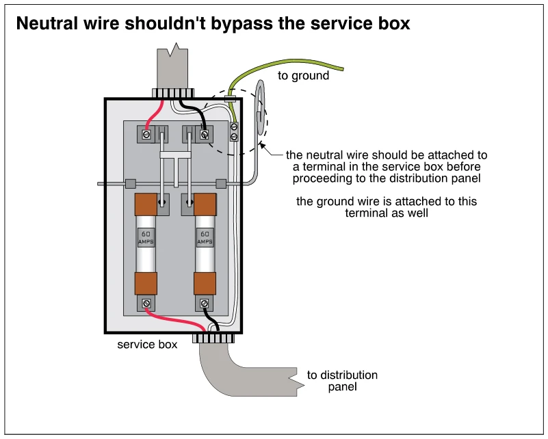
0544Neutral wire shouldn't bypass the service box
· p. 91
The illustration shows an open service box containing a two-pole disconnect and two 60-amp cartridge fuses, with conductors entering above and continuing below to a distribution panel. Red and black conductors connect through the disconnect and fuse assembly. The neutral conductor runs along the right side of the enclosure, where a dashed highlight and arrow identify the neutral-terminal connection area. The annotations state that the neutral must attach to a terminal in the service box before continuing to the distribution panel, and that the grounding wire attaches to this terminal as well. The figure warns against bypassing this service-box neutral connection.
 0545
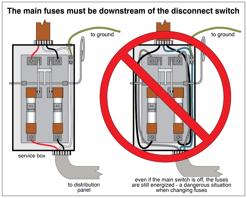
0545The main fuses must be downstream of the disconnect switch
· p. 91
The illustration compares two fused electrical service boxes with disconnect switches, cartridge fuses, grounding connections, and outgoing conductors. In the left arrangement, incoming service conductors connect to the disconnect ahead of the fuses, and the outgoing conductors lead to the distribution panel. The right arrangement is crossed out with a red prohibition symbol and shows wiring that places the fuses electrically upstream of the disconnect. As the annotation warns, these improperly connected fuses remain energized even when the main switch is off, creating a hazard when changing fuses.
 0546
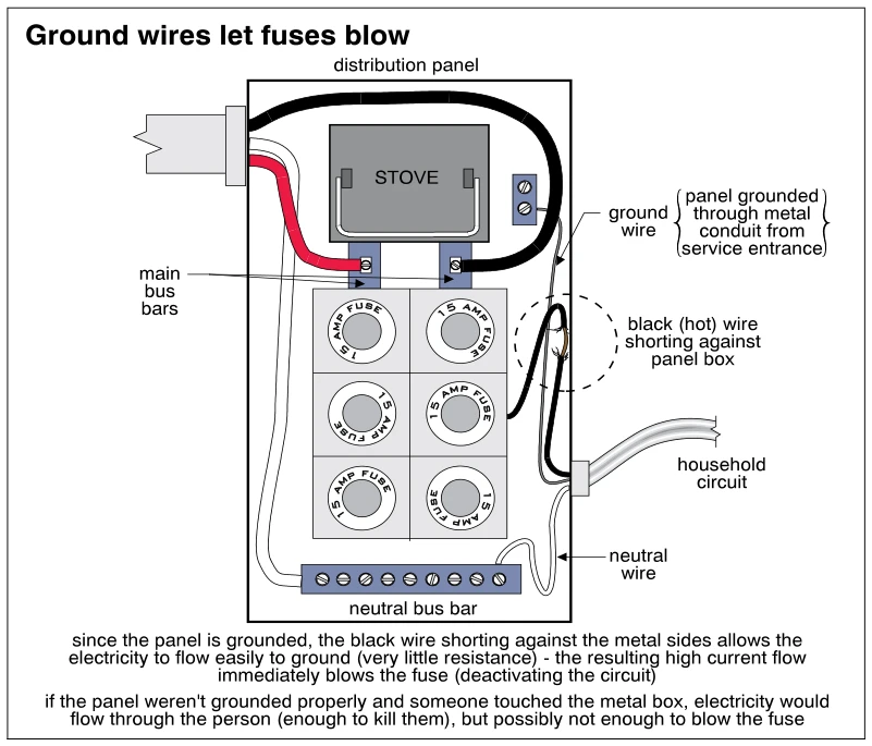
0546Ground wires let fuses blow
· p. 91
The illustration shows a metal electrical distribution panel with main bus bars, six 15-amp plug fuses, a stove fuse block, and a neutral bus bar. A household branch circuit enters the panel at the right, where a circled detail shows its black hot wire shorting against the metal enclosure. A ground wire and grounding through the metal service-entrance conduit are identified. The annotations explain that grounding provides a low-resistance fault-current path so the resulting high current blows the fuse, disconnecting the circuit. They also warn that an improperly grounded enclosure could conduct lethal current through a person without enough current to blow the fuse.
 0546.5
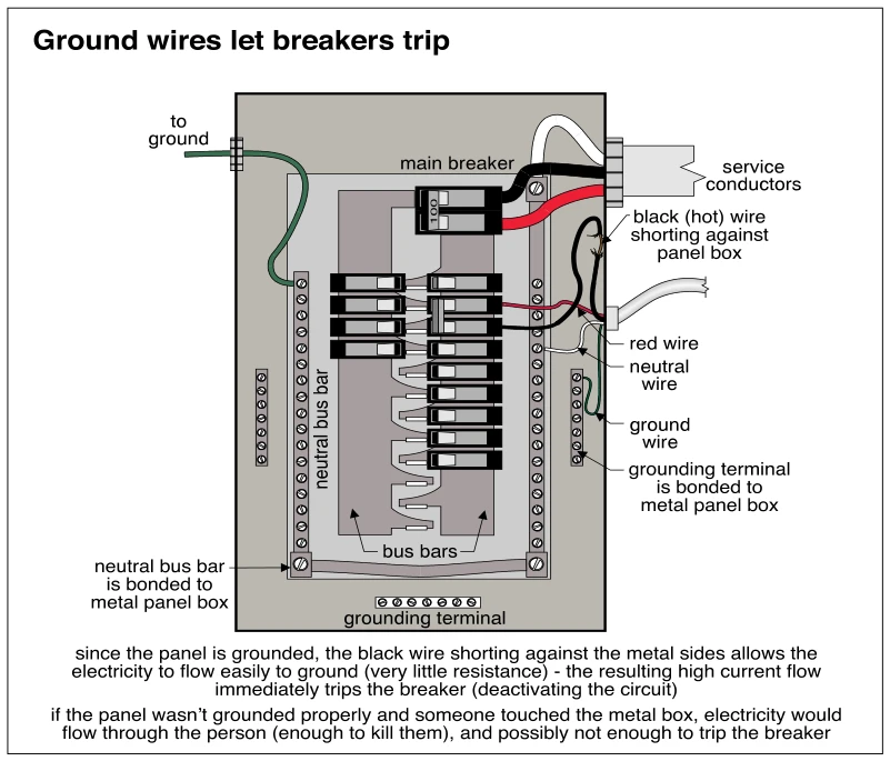
Ground wires let breakers trip
· p. 91
The illustration shows an electrical service panel with a main breaker, branch-circuit breakers, bus bars, neutral bus bars, and grounding terminals. Incoming service conductors enter at the upper right, and a grounding conductor exits at the upper left. A black hot wire is shown shorting against the metal panel enclosure. The neutral bus bar and grounding terminal are labeled as bonded to the enclosure, providing a low-resistance fault-current path that allows the breaker to trip. The bottom annotations contrast this protection with the potentially fatal shock hazard of touching an improperly grounded enclosure.
 0547
0547Electrical path for ground and neutral wires
· p. 92
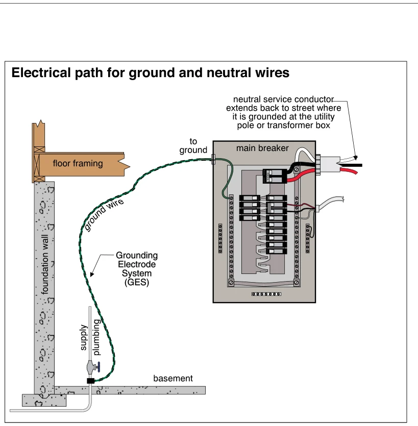
The illustration shows an electrical service panel beside a basement foundation wall and floor framing. A green grounding conductor runs from a terminal bar inside the panel to a connection on the incoming supply plumbing near the basement floor. This connection is identified as the Grounding Electrode System (GES). The panel contains a main breaker, branch circuit breakers, and terminal bars. An annotation explains that the neutral service conductor extends back to the street, where it is grounded at the utility pole or transformer box.
 0548
0548Bonding the gas piping
· p. 92
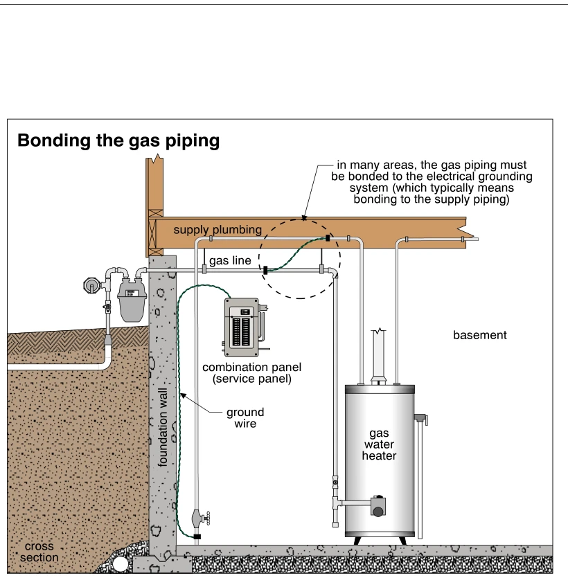
A basement cross section shows a gas meter outside the foundation wall, a service panel, supply plumbing, and a gas water heater. The gas line passes through the foundation wall and runs overhead before descending to the water heater. A highlighted bonding jumper connects the gas line to the supply plumbing near the basement ceiling. A separate ground wire runs from the service panel to a clamp on the supply plumbing near the floor. The annotation explains that in many areas gas piping must be bonded to the electrical grounding system, typically by bonding it to the supply piping.
 0549
0549Arcing and sparks
· p. 92
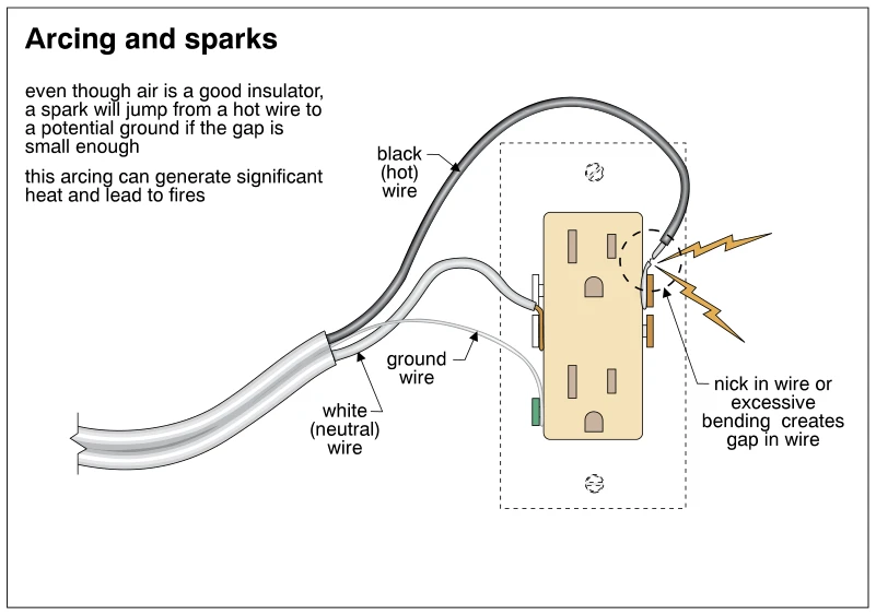
The illustration shows a duplex receptacle connected to black hot, white neutral, and ground wires emerging from a sheathed cable. A gap is depicted in the hot wire near its connection to the receptacle, with sparks indicating electrical arcing. The callout attributes the gap to a nick in the wire or excessive bending. Explanatory text notes that sparks can jump from a hot wire to a potential ground across a sufficiently small air gap, generating significant heat and potentially causing fires.
 0550
0550Electrical path for ground and neutral wires
· p. 92
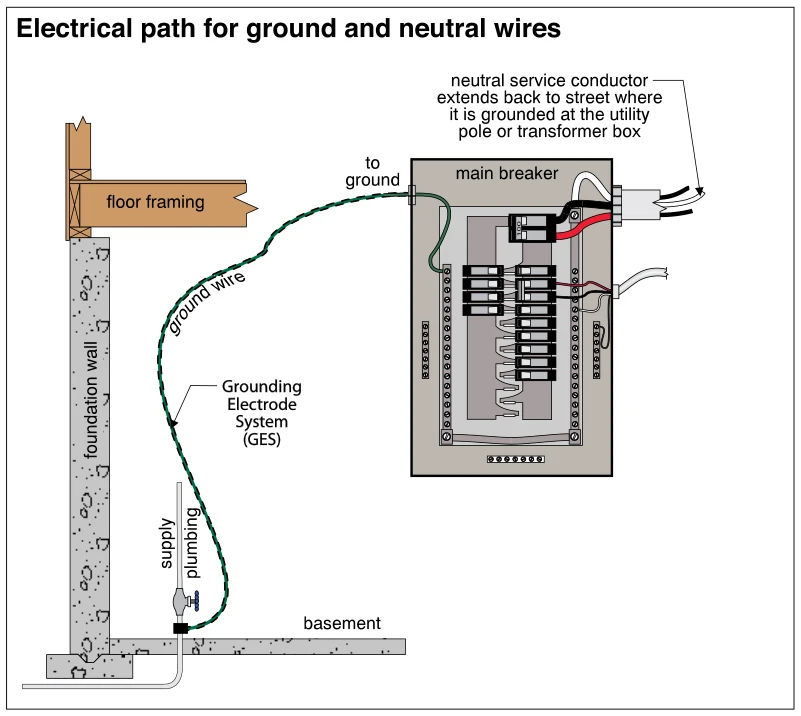
The illustration shows an open main electrical panel beside a basement foundation wall and floor framing. A green grounding conductor runs from a terminal bar in the panel to a connection on the incoming water supply piping near the basement floor. The conductor is identified as part of the Grounding Electrode System (GES). Service conductors enter the panel at the upper right, and an annotation explains that the neutral service conductor returns to the street and is grounded at the utility pole or transformer box. Branch circuit breakers, terminal bars, and outgoing circuit wiring are also shown.
 0551
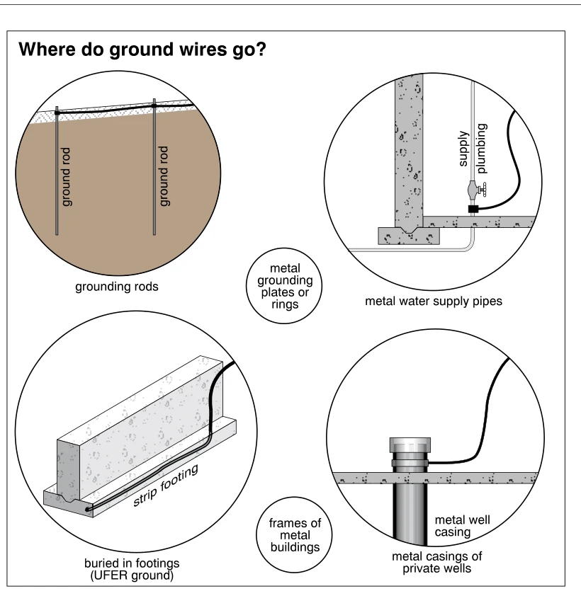
0551Where do ground wires go?
· p. 93
The illustration identifies locations where electrical grounding conductors can connect to grounding electrodes. Separate circular details show interconnected rods driven into soil, a conductor clamped to metal water supply piping, and a conductor buried in a concrete strip footing, labeled as a UFER ground. Another detail shows a grounding conductor attached to a metal private-well casing. Text-only circles also identify metal grounding plates or rings and the frames of metal buildings as grounding locations. No defects or contrasting improper installations are depicted.
 0552
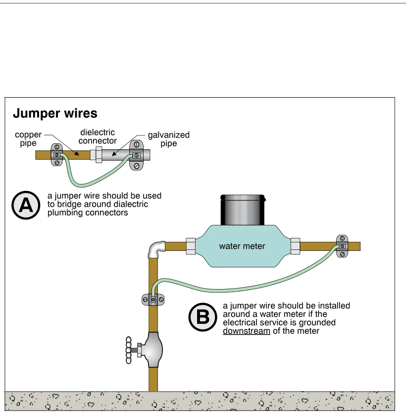
0552Jumper wires
· p. 93
Two diagrams illustrate bonding jumper wires used to maintain electrical continuity across interruptions in metal water piping. Diagram A shows a jumper clamped to copper and galvanized pipes on opposite sides of a dielectric connector. Diagram B shows a jumper clamped to piping on either side of a water meter, bypassing the meter assembly. The annotation specifies that the meter jumper should be installed if the electrical service is grounded downstream of the meter. A shutoff valve is shown on the vertical pipe below the meter.
 0553
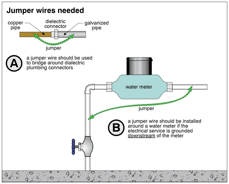
0553Jumper wires needed
· p. 93
The illustration shows two locations where bonding jumper wires are needed to maintain electrical continuity through metal water piping. Detail A shows a jumper bridging a dielectric connector between copper and galvanized pipe. Detail B shows a water meter in a pipe assembly with an elbow and shutoff valve, and a jumper bypassing the meter. The annotation specifies that the meter jumper is needed if the electrical service is grounded downstream of the meter.
 0554
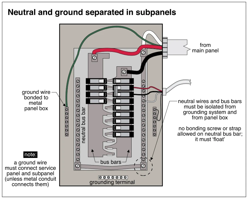
0554Neutral and ground separated in subpanels
· p. 93
The illustration shows an electrical subpanel with feeder conductors entering from the main panel, two hot bus bars, circuit breakers, neutral bus bars, and grounding terminals. The feeder grounding wire connects to a terminal bonded to the metal panel enclosure. The neutral wires and neutral bus bars are isolated from both the enclosure and the grounding system, with an annotation prohibiting a neutral bonding screw or strap. A note states that a grounding wire must connect the service panel and subpanel unless metal conduit connects them.
Service Box, Grounding And Panels ·Distribution Panelsp. 94
 0555
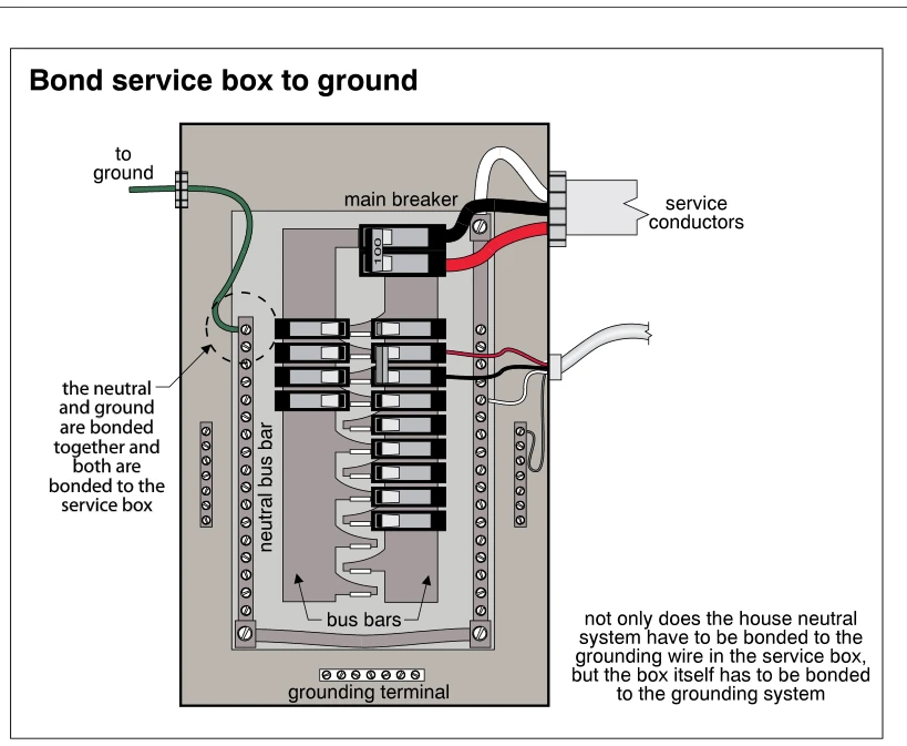
0555Bond service box to ground
· p. 94
The illustration shows an open electrical service panel with a main breaker, branch circuit breakers, bus bars, neutral terminals, and a grounding terminal. Service conductors enter at the upper right, and a green conductor labeled “to ground” connects to the neutral bus bar at the upper left. A dashed circle highlights the neutral-to-ground bonding location. The annotations emphasize that the neutral and grounding system must be bonded together at the service box and that the metal enclosure must also be bonded to the grounding system.
 0556
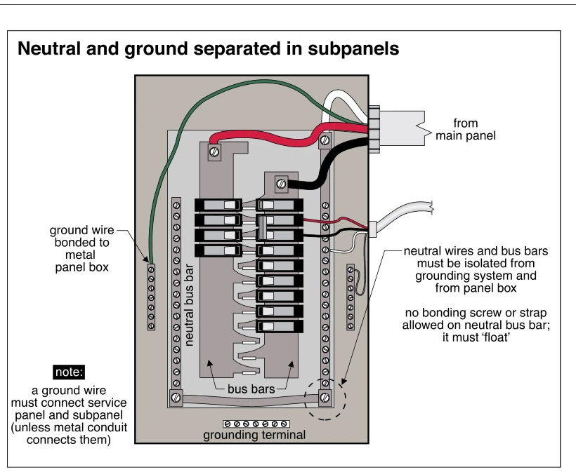
0556Neutral and ground separated in subpanels
· p. 94
The illustration shows an open subpanel supplied by red and black hot conductors, a white neutral conductor, and a green grounding conductor from the main panel. Circuit breakers connect to the interior bus bars, with neutral terminal bars located along the sides. The grounding conductor is bonded to the metal panel box, while the neutral wires and bus bars are required to remain isolated from both the enclosure and the grounding system. An annotation prohibits a bonding screw or strap on the neutral bus bar, and a note requires a grounding wire between the service panel and subpanel unless metal conduit connects them.
 0557
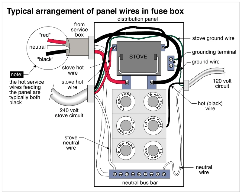
0557Typical arrangement of panel wires in fuse box
· p. 94
The illustration shows the internal wire arrangement of a fuse-type electrical distribution panel supplied from a service box. Two hot supply conductors feed the panel, with an inset identifying the red, black, and neutral conductors and noting that the hot service wires are typically both black. A stove fuse unit and six 15-amp plug fuses are shown inside the enclosure. The 240-volt stove circuit has two hot wires, a neutral routed to the bottom neutral bus bar, and a ground routed to a grounding terminal on the right. A separate 120-volt circuit is shown with a black hot wire, a neutral connected to the neutral bus bar, and a ground wire connected at the grounding terminal.
 0557.5
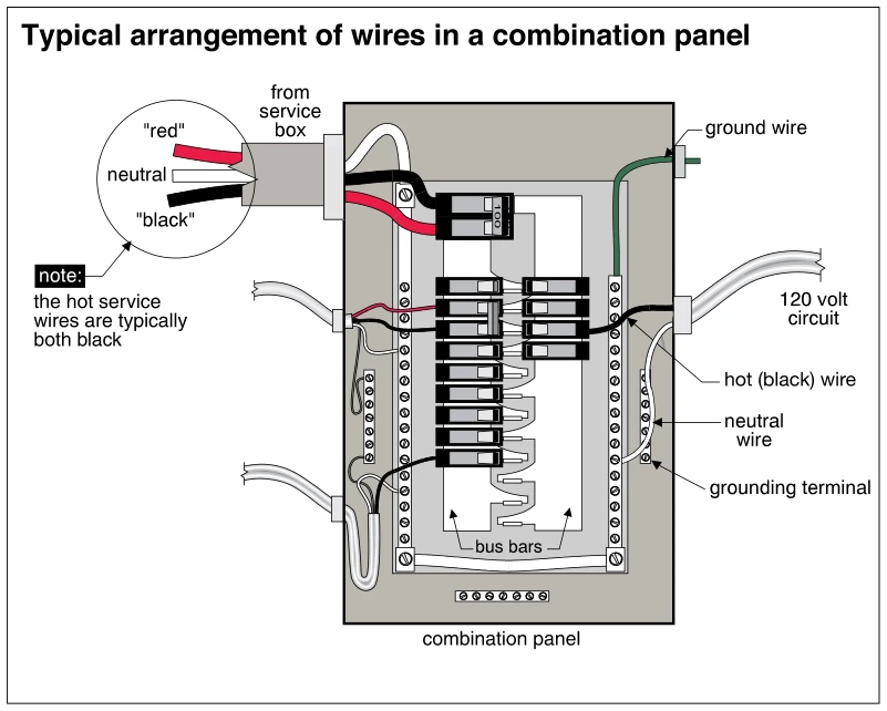
Typical arrangement of wires in a combination panel
· p. 94
The illustration shows an open combination electrical panel with incoming conductors from a service box and several outgoing branch-circuit cables. Two incoming hot conductors connect to a large double-pole breaker, while the neutral connects to a terminal bar along the side of the panel. Branch-circuit breakers are arranged over central bus bars, with terminal bars positioned along both sides of the enclosure. A labeled 120-volt circuit shows its black hot wire connected to a breaker, its white neutral connected to a side terminal bar, and its grounding conductor connected to a grounding terminal. A green ground wire enters at the upper right, and an inset notes that the incoming hot service wires are typically both black despite being distinguished as red and black in the drawing.
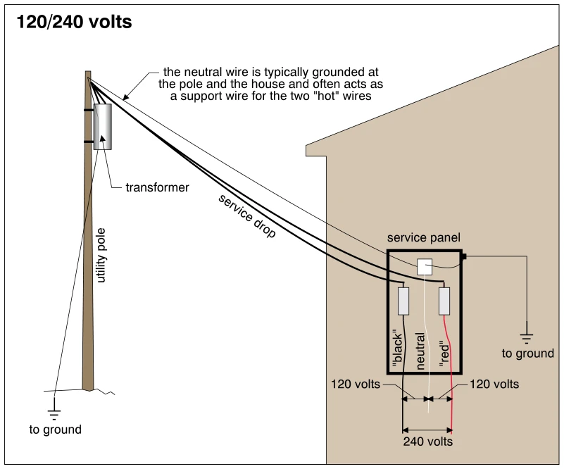 0558
0558120/240 volts
· p. 94
The illustration shows a pole-mounted utility transformer supplying a house service panel through an overhead service drop. Two hot conductors, labeled "black" and "red," and a neutral conductor enter the panel. Voltage annotations indicate 120 volts between either hot conductor and neutral, and 240 volts between the two hot conductors. Ground connections are shown at the utility pole and the house. A note explains that the neutral is typically grounded at both locations and often supports the two hot wires.
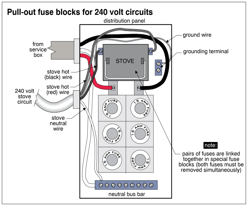 0559
0559Pull-out fuse blocks for 240 volt circuits
· p. 94
The illustration shows a distribution panel containing a pull-out fuse block labeled STOVE above six 15-amp plug fuses. The 240-volt stove circuit has black and red hot conductors connected at the stove fuse block and a neutral conductor routed to the neutral bus bar at the bottom of the panel. A ground wire is identified at a separate grounding terminal on the side of the enclosure. The annotation explains that paired fuses are linked in special pull-out blocks so both fuses must be removed simultaneously.
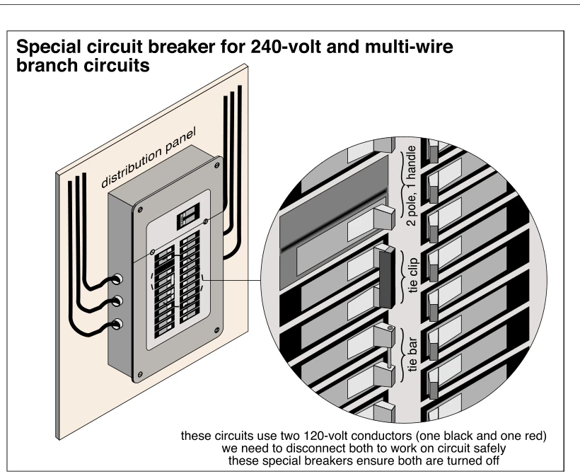 0560
0560Special circuit breaker for 240-volt and multi-wire branch circuits
· p. 95
The illustration shows an electrical distribution panel with a magnified view of paired circuit breakers. The detail identifies three arrangements for operating paired poles together: a two-pole breaker with one handle, a tie clip, and a tie bar. The annotation explains that 240-volt and multi-wire branch circuits use two 120-volt conductors, identified as black and red. Both conductors must be disconnected to work on the circuit safely, and the illustrated handle arrangements ensure both are turned off together.
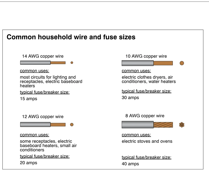 0561
0561Common household wire and fuse sizes
· p. 95
The chart depicts four sizes of insulated copper wire with exposed conductors and end views, pairing each with common household uses and typical fuse or circuit breaker ratings. The 14 AWG wire is paired with 15 amps for lighting, receptacles, and electric baseboard heaters; 12 AWG is paired with 20 amps for some receptacles, electric baseboard heaters, and small air conditioners. The 10 AWG wire is paired with 30 amps for electric clothes dryers, air conditioners, and water heaters, while 8 AWG is paired with 40 amps for electric stoves and ovens. The three smaller sizes are illustrated as solid conductors, and the 8 AWG wire is shown as stranded. No distribution panel, fuse, or circuit breaker is physically depicted.
 0562
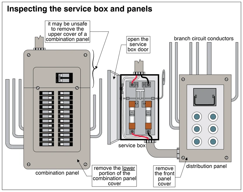
0562Inspecting the service box and panels
· p. 95
The illustration compares access for inspection of a combination panel with access to a separate service box and distribution panel. The combination panel has a main breaker above two columns of branch circuit breakers, with an annotation warning that removing its upper cover may be unsafe. Another annotation directs removal of the lower portion of the combination panel cover. The separate service box is shown with its door open, exposing a disconnect mechanism, two cartridge fuses, and conductors. A conduit connects the service box to a distribution panel with six circular fuse positions; annotations identify branch circuit conductors and direct removal of the front panel cover.
 0563
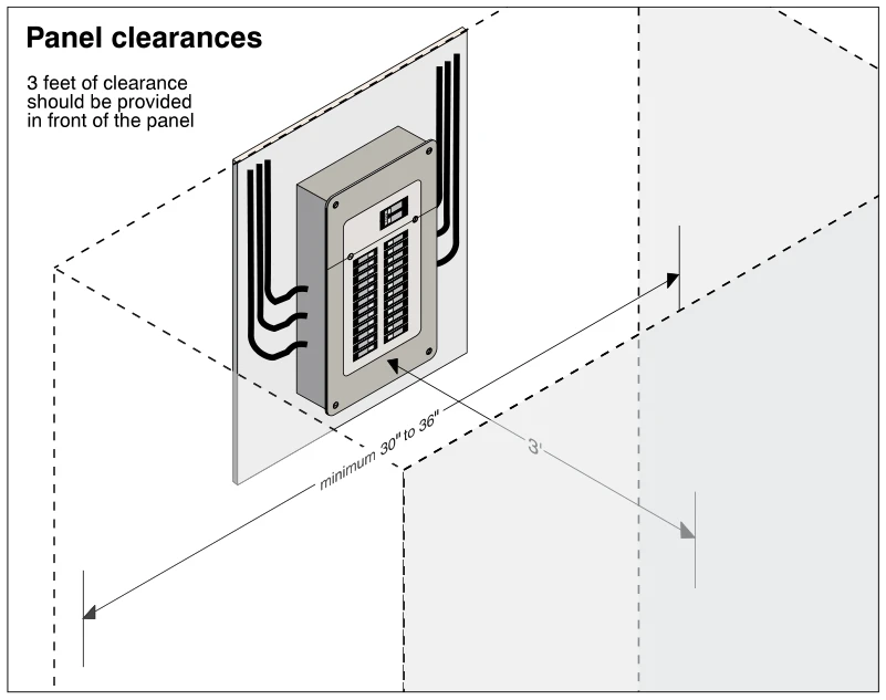
0563Panel clearances
· p. 95
The illustration shows a wall-mounted electrical distribution panel with two columns of circuit breakers and wiring entering both sides. Dashed lines define an unobstructed working space in front of the panel. A dimension arrow indicates a 3-foot clearance outward from the panel face, and another labels the working-space width as minimum 30 to 36 inches. The drawing illustrates clearance provisions rather than an obstructed or defective installation.
 0564
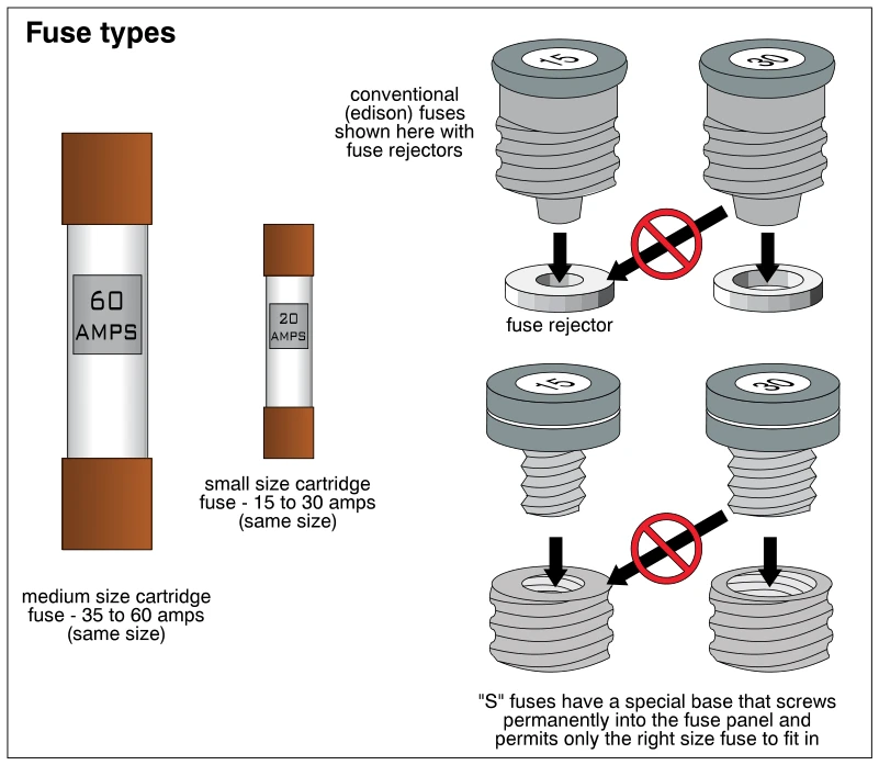
0564Fuse types
· p. 95
The illustration compares cartridge fuses, conventional Edison screw-base fuses with fuse rejectors, and Type S fuses with permanent adapter bases. Two cartridge fuse sizes are shown: a medium size for 35–60 amps and a small size for 15–30 amps, illustrated with 60-amp and 20-amp examples. The upper-right diagrams show 15-amp and 30-amp Edison fuses fitting their respective rejectors, with a prohibition symbol indicating that the 30-amp fuse cannot fit the 15-amp rejector. The lower-right diagrams show Type S fuses and threaded bases that remain in the fuse panel and accept only the appropriate fuse size. Arrows and prohibition symbols emphasize prevention of substitution with a higher-amperage fuse.
 0565
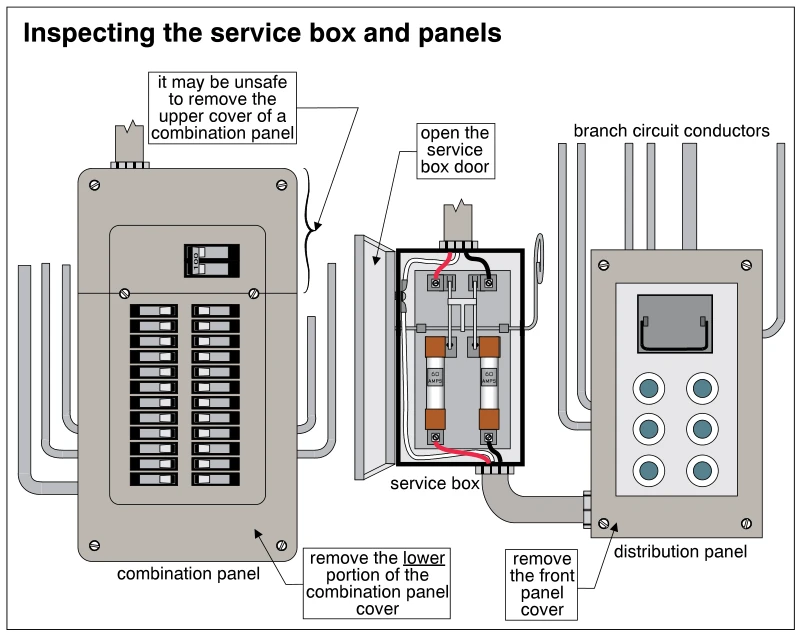
0565Inspecting the service box and panels
· p. 95
The illustration shows a combination service and breaker panel alongside a separate fused service box and distribution panel. The combination panel has an upper main-disconnect section and two columns of branch circuit breakers below; an annotation warns that removing its upper cover may be unsafe and directs removal of the lower cover portion. The separate service box is shown with its door open, exposing disconnect hardware, two 60-amp fuses, and wiring. A conduit connects this service box to a distribution panel with six circular fuse positions and branch circuit conductors extending from the enclosure. An arrow directs removal of the distribution panel's front cover for inspection.
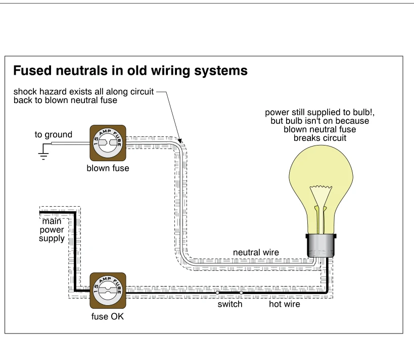 0566
0566Fused neutrals in old wiring systems
· p. 96
The schematic shows an old lighting circuit with fuses in both the hot and neutral conductors. The hot conductor runs from the main power supply through an intact fuse and a closed switch to a light bulb. The neutral conductor returns from the bulb through a blown fuse, with a ground connection shown on the supply side of that fuse. Although the bulb is off because the neutral fuse has opened the circuit, the hot conductor still supplies power to the bulb. The illustration identifies a shock hazard along the circuit back to the blown neutral fuse.
 0567
0567Securing the panel
· p. 96
The illustration shows an electrical distribution panel mounted on a rectangular support board. The panel has a metal enclosure and front cover with an upper breaker and two vertical rows of branch-circuit breakers. Cables run along both sides of the support and enter the panel enclosure. The annotation emphasizes that the panel should be well secured to its support; no loose mounting or other defect is depicted.
 0568
0568Panel mounting
· p. 96
The illustration shows an electrical distribution panel mounted on a rectangular backing board labeled panel support. The panel has a front cover with two columns of branch circuit breakers and a larger breaker above them. Multiple electrical cables run vertically along the backing and curve into the sides of the enclosure. The notes state that many jurisdictions require non-combustible backing, such as drywall, and that plywood or wood planking were commonly used in older installations. No specific mounting defect is identified in the drawing.
 0569
0569Panel openings
· p. 96
The illustration shows an electrical distribution panel mounted on a support board, with a main breaker and two columns of branch circuit breakers. Electrical cables enter the metal enclosure through fittings on its sides. Dashed outlines identify uncovered circular openings in the enclosure side and unused breaker openings in the panel front. The annotation specifies that exposed openings allowing access to the panel interior should be fitted with secure covers.
 0570
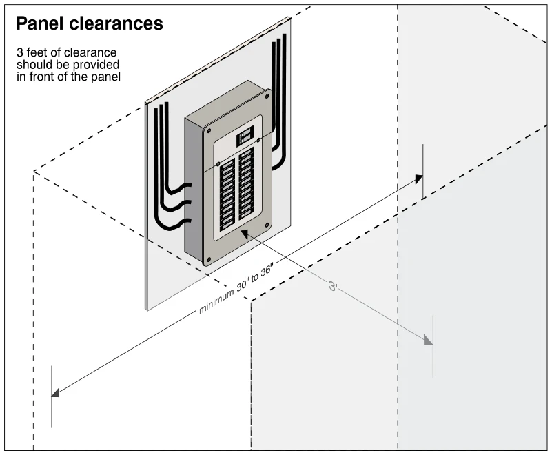
0570Panel clearances
· p. 96
The illustration shows a wall-mounted electrical distribution panel with two columns of circuit breakers and wiring entering along both sides. Dashed lines outline the unobstructed working space in front of the panel. A dimension arrow indicates 3 feet of clearance extending outward from the panel face. A second dimension across the working space is labeled minimum 30" to 36".
 0571
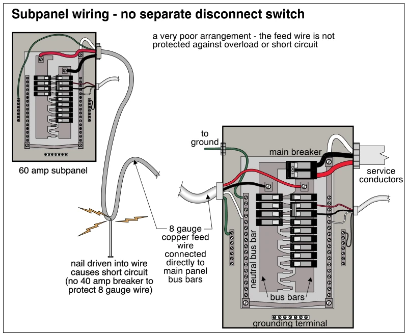
0571Subpanel wiring - no separate disconnect switch
· p. 96
The illustration shows a main electrical distribution panel supplying a 60 amp subpanel through an 8 gauge copper feeder. The feeder is connected directly to the main panel bus bars rather than through a dedicated feeder circuit breaker. A nail penetrating the feeder is shown causing a short circuit, with sparks at the damaged cable. The annotations identify the absence of a 40 amp breaker to protect the feeder against overload or short circuit. The main panel also shows its main breaker, service conductors, neutral bus bar, grounding terminal, and connection to ground.
 0572
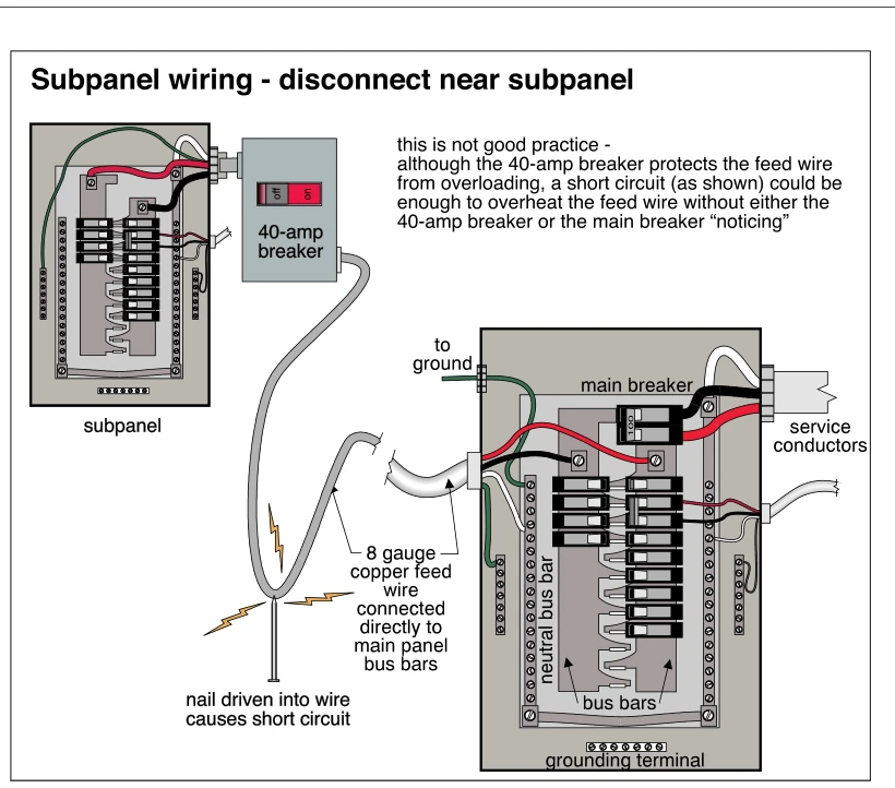
0572Subpanel wiring - disconnect near subpanel
· p. 97
The illustration shows a main distribution panel feeding a subpanel through an 8 gauge copper feed wire connected directly to the main panel bus bars. A separate 40-amp breaker is located beside the subpanel, at the receiving end of the feeder. A nail driven into the feeder between the panels is shown causing a short circuit. The annotation identifies this as poor practice: the 40-amp breaker protects against overloading but may not protect the upstream feeder from the illustrated short circuit, and the main breaker may not respond before the feeder overheats. The main panel also shows service conductors, a main breaker, branch breakers, a neutral bus bar, and a grounding terminal.
 0573
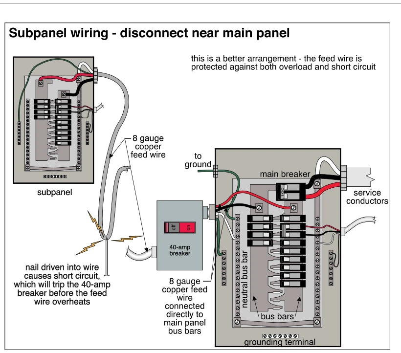
0573Subpanel wiring - disconnect near main panel
· p. 97
The illustration shows a main electrical panel supplying a subpanel through a separate 40-amp breaker located near the main panel. An 8 gauge copper feeder connects directly to the main panel bus bars and passes through the nearby breaker before continuing to the subpanel. The main panel includes a main breaker, service conductors, branch circuit breakers, bus bars, a neutral bus bar, and a grounding terminal. A nail penetrating the feeder illustrates a short circuit that trips the 40-amp breaker before the feeder overheats. The annotation identifies this as a better arrangement because the feeder is protected against both overload and short circuit.
 0574
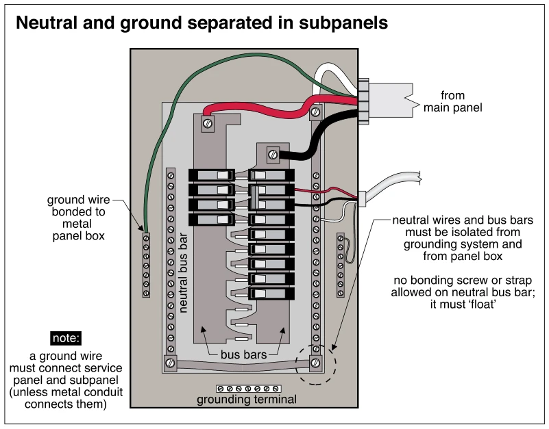
0574Neutral and ground separated in subpanels
· p. 97
The illustration shows an electrical subpanel with its cover removed, exposing circuit breakers, bus bars, neutral terminals, and grounding terminals. Red and black feeder conductors from the main panel supply the bus bars, while white and green conductors provide neutral and grounding connections. The ground wire is bonded to the metal panel box, but the neutral wires and bus bars are isolated from both the enclosure and grounding system. An annotation prohibits a bonding screw or strap on the neutral bus bar and states that it must “float.” A note specifies a ground-wire connection between the service panel and subpanel unless metal conduit connects them.
 0575
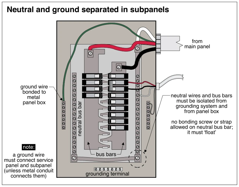
0575Neutral and ground separated in subpanels
· p. 97
The illustration shows an electrical subpanel with its cover removed, exposing circuit breakers, bus bars, neutral bars, and grounding terminals. Feeder conductors enter from the main panel, with the green ground wire bonded to the metal panel enclosure. The neutral wires and neutral bus bars are isolated from both the enclosure and the grounding system, and a circled area emphasizes that no neutral bonding screw or strap is permitted. A branch circuit exits through the right side of the enclosure. A note states that a ground wire must connect the service panel and subpanel unless metal conduit connects them.
 0576
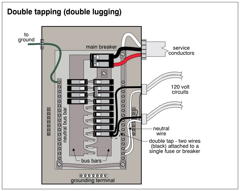
0576Double tapping (double lugging)
· p. 97
The illustration shows an open electrical distribution panel with service conductors feeding a main breaker and bus bars supplying branch circuit breakers. Two outgoing 120-volt circuits have black conductors connected to the same branch breaker terminal, identified as a double tap or double lug. White neutral wires terminate on a vertical neutral bus bar beside the breakers. A green conductor leads from the neutral bus assembly toward ground, and a separate grounding terminal strip is shown at the bottom of the enclosure. The highlighted improper practice is connecting two circuit conductors to a single breaker connection.
 0577
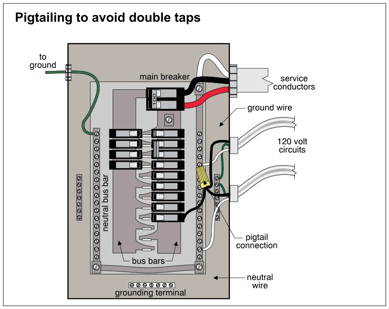
0577Pigtailing to avoid double taps
· p. 97
The illustration shows an open electrical distribution panel with a main breaker, branch circuit breakers, bus bars, neutral bus bars, and grounding terminals. Service conductors enter at the upper right, and two 120-volt circuit cables enter along the right side. A yellow wire connector joins the two black branch circuit conductors to a single black pigtail connected to a branch breaker. This arrangement avoids placing two conductors under one breaker terminal. White neutral conductors and green grounding conductors are shown routed to terminal bars.
 0578
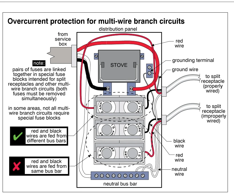
0578Overcurrent protection for multi-wire branch circuits
· p. 98
The illustration shows a fused electrical distribution panel with a stove fuse block, three paired branch-circuit fuse blocks, a grounding terminal, and a neutral bus bar. Red and black conductors supply two multi-wire branch circuits leading to split receptacles, with neutral and grounding conductors also shown. A green check identifies the properly wired arrangement, where the red and black wires are fed from different bus bars. A red cross identifies the improperly wired arrangement, where both wires are fed from the same bus bar. A note explains that special linked fuse blocks allow both fuses of a multi-wire branch circuit to be removed simultaneously, while noting that requirements vary by area.
 0579
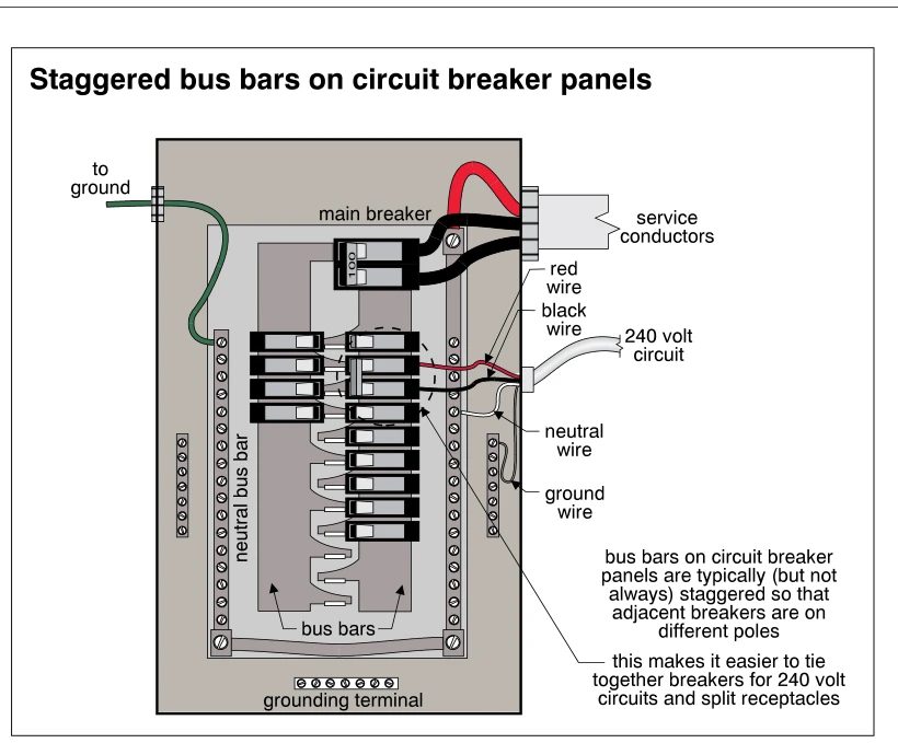
0579Staggered bus bars on circuit breaker panels
· p. 98
The illustration shows an open circuit breaker distribution panel with service conductors feeding a main breaker and staggered bus bars supplying branch circuit breakers. The interleaved bus bar arrangement places adjacent breakers on different poles, as explained by the annotations. A 240 volt circuit is shown with red and black wires connected to adjacent breakers, along with neutral and ground wires routed to terminal bars. The drawing also identifies the neutral bus bar, grounding terminal, and a conductor leading to ground. This is an informational diagram of panel layout rather than a depiction of a defect.
 0580
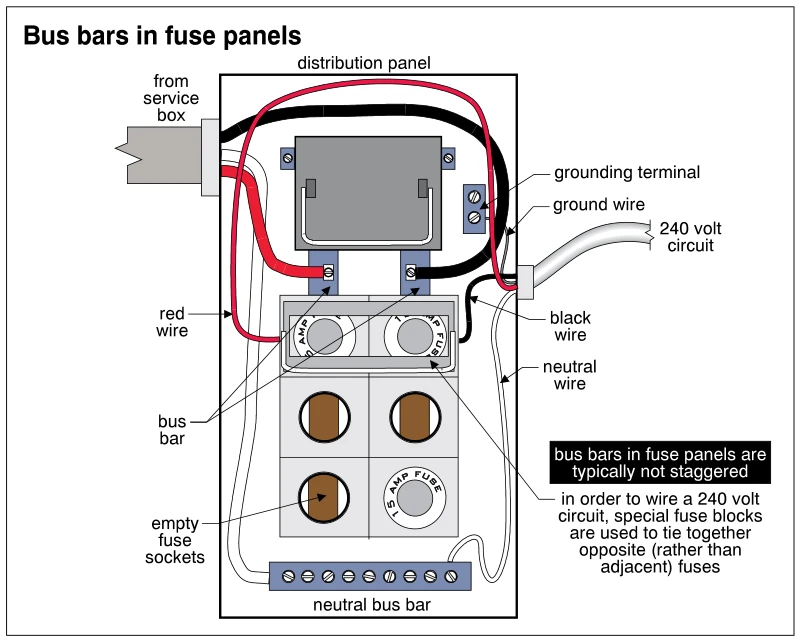
0580Bus bars in fuse panels
· p. 98
The illustration shows the interior of a fuse distribution panel with incoming conductors from a service box, two vertical bus bars, fuse sockets, and a neutral bus bar at the bottom. Red and black conductors connect to the two bus bars, and several empty fuse sockets expose the bars behind them. A special fuse block spans opposite fuse positions to supply a labeled 240 volt circuit. The annotations explain that fuse-panel bus bars are typically not staggered, so a 240 volt circuit uses opposite rather than adjacent fuses. A grounding terminal, ground wire, and neutral wire are also identified.
 0581
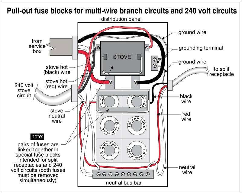
0581Pull-out fuse blocks for multi-wire branch circuits and 240 volt circuits
· p. 98
The illustration shows a fused distribution panel supplied from a service box, with a 240-volt stove circuit on the left and a multi-wire branch circuit feeding a split receptacle on the right. The stove circuit has black and red hot wires and a neutral wire, with a pull-out block marked STOVE. A second pull-out block groups a pair of plug fuses above four individual plug fuses. Neutral conductors terminate at the neutral bus bar at the bottom, while ground wires are shown connected at a separate grounding terminal. The note explains that paired fuses in these special blocks must be removed simultaneously for split receptacles and 240-volt circuits.
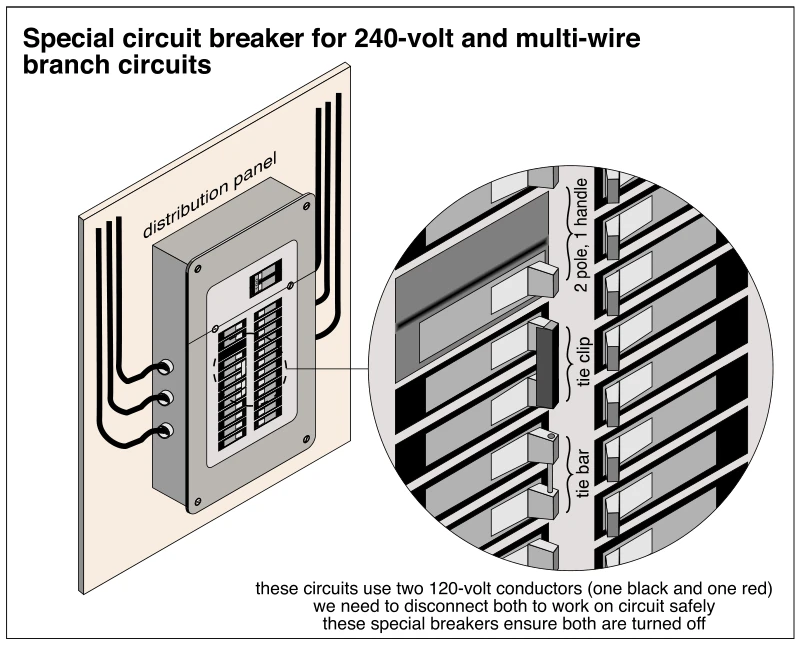 0582
0582Special circuit breaker for 240-volt and multi-wire branch circuits
· p. 98
The illustration shows an electrical distribution panel with an enlarged view of paired circuit breakers. The detail identifies three linked operating arrangements: a two-pole breaker with one handle, a tie clip, and a tie bar. These arrangements link the operation of breakers serving 240-volt and multi-wire branch circuits. The annotation explains that these circuits use two 120-volt conductors, one black and one red, and that both must be disconnected to work on the circuit safely.
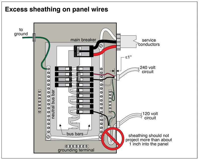 0583
0583Excess sheathing on panel wires
· p. 98
The illustration shows an open electrical distribution panel with a main breaker, branch-circuit breakers, bus bars, neutral bus bars, and a grounding terminal. Service conductors enter at the upper right, and cables labeled for 240 volt and 120 volt circuits enter through the right side. At the upper branch-circuit entry, a dimension indicates that cable sheathing should extend no more than 1 inch into the panel. The lower cable has a long loop of outer sheathing inside the enclosure, highlighted with a red prohibition symbol and an annotation identifying the excessive extension as improper.
The Distribution System ·Branch Circuit Wiring (Distribution Wiring)p. 99
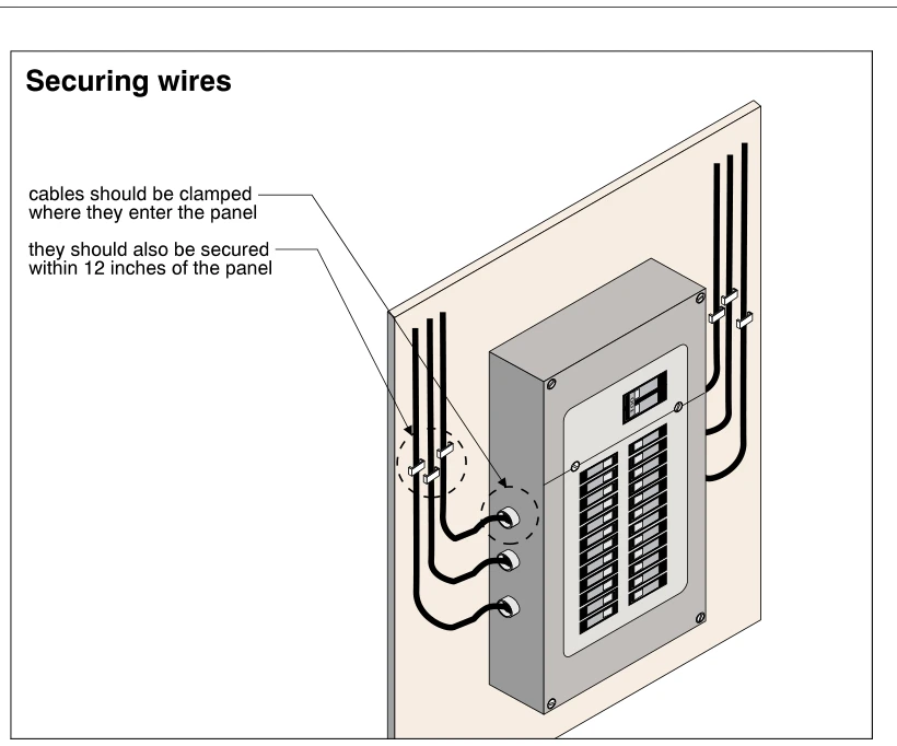 0584
0584Securing wires
· p. 99
The illustration shows an electrical distribution panel mounted on a backing board, with cables entering both sides of the enclosure. Clamps secure the cables at the panel entry points. Staples or straps fasten the cables to the backing board near the panel. The annotations specify clamping at panel entries and securing cables within 12 inches of the panel.
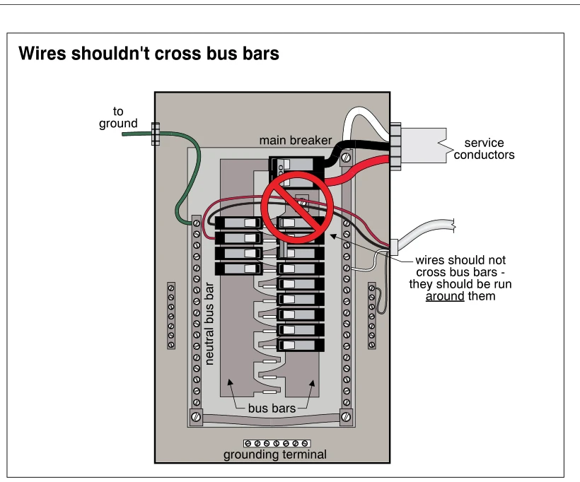 0585
0585Wires shouldn't cross bus bars
· p. 99
The illustration shows the interior of an electrical distribution panel with a main breaker, two columns of branch circuit breakers, central bus bars, neutral terminals, and a grounding terminal. Service conductors enter at the upper right and connect within the panel. Branch circuit wires entering from the right are routed across the central bus bar area, highlighted by a red prohibition symbol. The annotation states that wires should be run around the bus bars rather than across them.
 0586
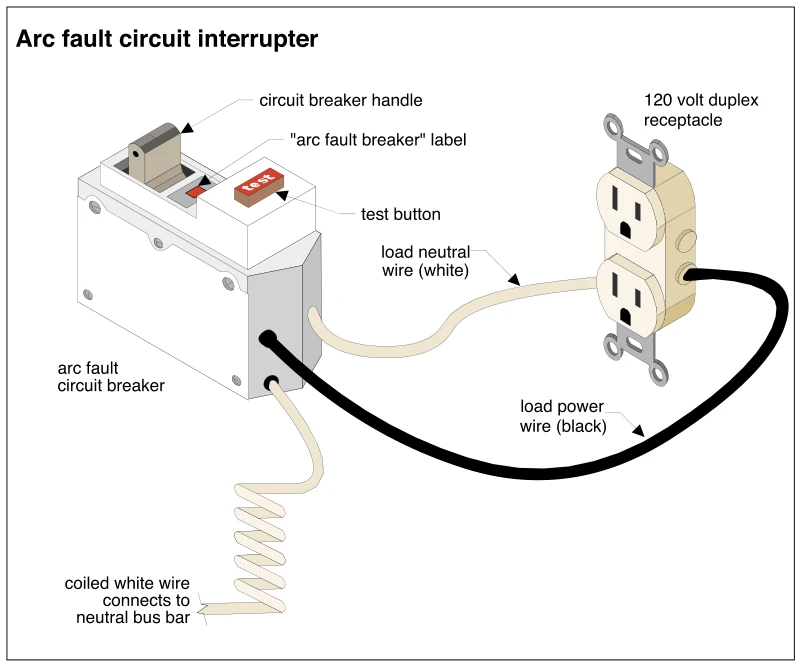
0586Arc fault circuit interrupter
· p. 99
The illustration shows an arc fault circuit interrupter breaker connected to a 120 volt duplex receptacle. Both the white load neutral wire and the black load power wire run between the breaker and the receptacle. A separate coiled white wire extends from the breaker and is annotated as connecting to the neutral bus bar, which is not shown. Callouts identify the breaker handle, arc fault breaker label, and test button.
 0587
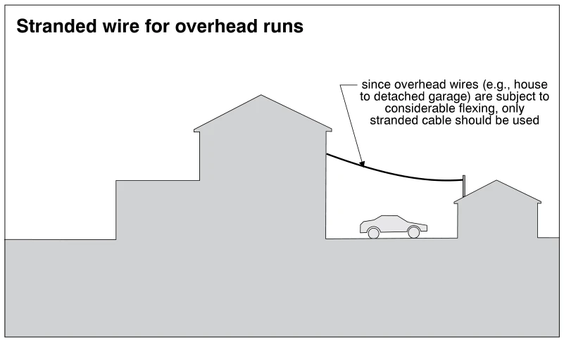
0587Stranded wire for overhead runs
· p. 99
The illustration shows an overhead electrical cable spanning from a house to a detached garage, with a car below the span. The cable sags between its attachment at the house and a vertical support at the garage. An arrow identifies the overhead run and explains that considerable flexing makes stranded cable necessary. The drawing presents stranded wire as the correct choice for this installation, without showing the cable's internal construction.
 0588
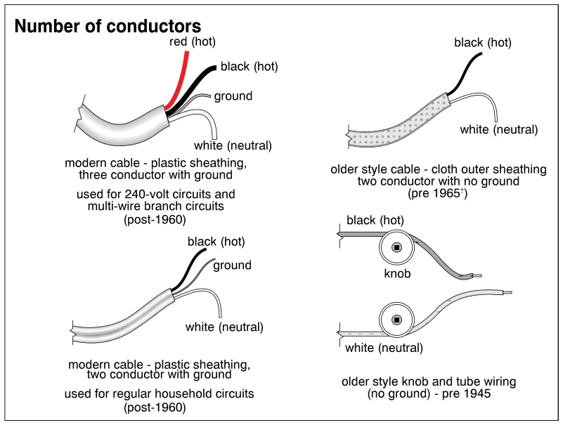
0588Number of conductors
· p. 99
The illustration compares four branch-circuit wiring configurations and identifies their hot, neutral, and grounding conductors. Modern plastic-sheathed three-conductor cable contains red and black hot conductors, a white neutral, and a separate ground, and is labeled for 240-volt and multi-wire branch circuits. Modern two-conductor cable contains a black hot, a white neutral, and a separate ground for regular household circuits. Older cloth-sheathed cable has a black hot and a white neutral with no grounding conductor. The knob-and-tube example shows separately routed hot and neutral conductors supported on knobs, also without a ground; tubes are not illustrated.
 0589
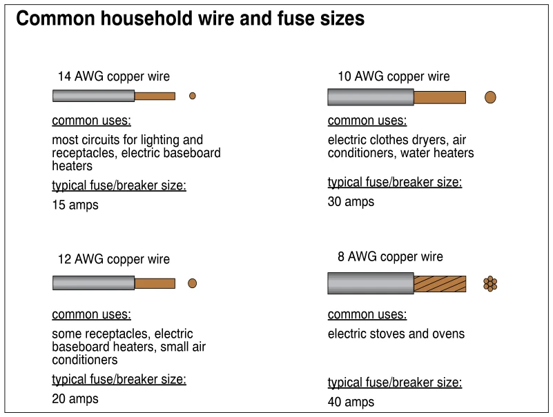
0589Common household wire and fuse sizes
· p. 99
The illustration charts four common copper conductor sizes with their household uses and typical fuse or circuit breaker ratings. Each conductor is shown with insulation, an exposed copper end, and an end-on cross-section; the 14, 12, and 10 AWG conductors are solid, while the 8 AWG conductor is stranded. The chart pairs 14 AWG with 15 amps for lighting, receptacles, and baseboard heaters, and 12 AWG with 20 amps for some receptacles, baseboard heaters, and small air conditioners. It pairs 10 AWG with 30 amps for clothes dryers, air conditioners, and water heaters, and 8 AWG with 40 amps for electric stoves and ovens. No wiring defect or installation is depicted.
 0590
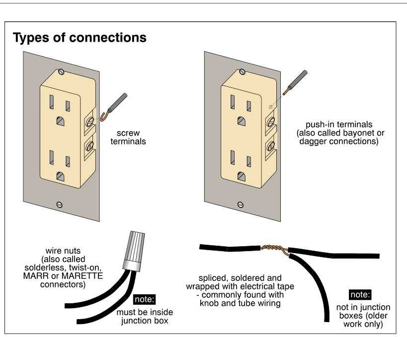
0590Types of connections
· p. 100
The illustration presents four types of electrical conductor connections. Two duplex receptacles demonstrate a hooked conductor for a screw terminal and a straight conductor for a push-in terminal. A twist-on wire connector joins two insulated conductors, with a note stating that this connection must be inside a junction box. A separate detail shows a twisted conductor splice described as soldered and wrapped with electrical tape, commonly found with knob and tube wiring. The accompanying note identifies splices outside junction boxes as an older-work-only condition.
 0591
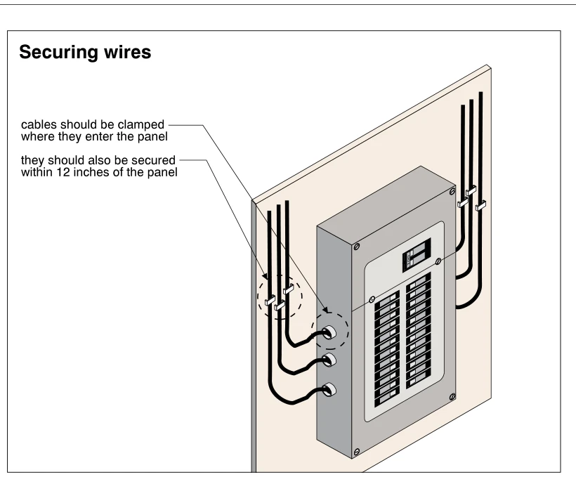
0591Securing wires
· p. 100
The illustration shows an electrical breaker panel mounted on a backing board, with cables routed into both sides of the enclosure. Clamps secure the cables where they enter the panel. Staples or straps attach the cables to the backing surface above the curved approaches to the panel. The annotations specify that cables should be clamped at panel entries and secured within 12 inches of the panel.
 0592
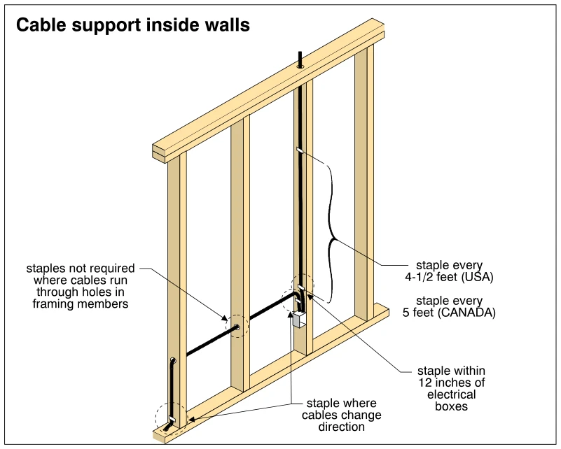
0592Cable support inside walls
· p. 100
The illustration shows electrical cables routed through an exposed wood-stud wall with top and bottom plates and an electrical box mounted to a stud. One cable runs vertically alongside a stud, while another passes horizontally through holes in the framing and bends downward near the bottom plate. Staples secure the cables along vertical runs, near the electrical box, and where cables change direction. The annotations specify staple spacing of 4-1/2 feet in the USA and 5 feet in Canada, and stapling within 12 inches of electrical boxes. Cables passing through holes in framing members are identified as not requiring staples at those locations.
 0593
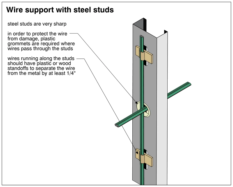
0593Wire support with steel studs
· p. 100
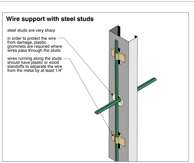
The illustration shows electrical wiring routed both through and along a steel wall stud. A plastic grommet lines the opening where a wire passes through the stud, protecting it from sharp metal edges. A vertical wire is secured along the stud with two standoff supports. The annotation specifies plastic or wood standoffs that maintain at least 1/4 inch of separation between the wire and the metal.
 0593.5
Wire installations below floors
· p. 100
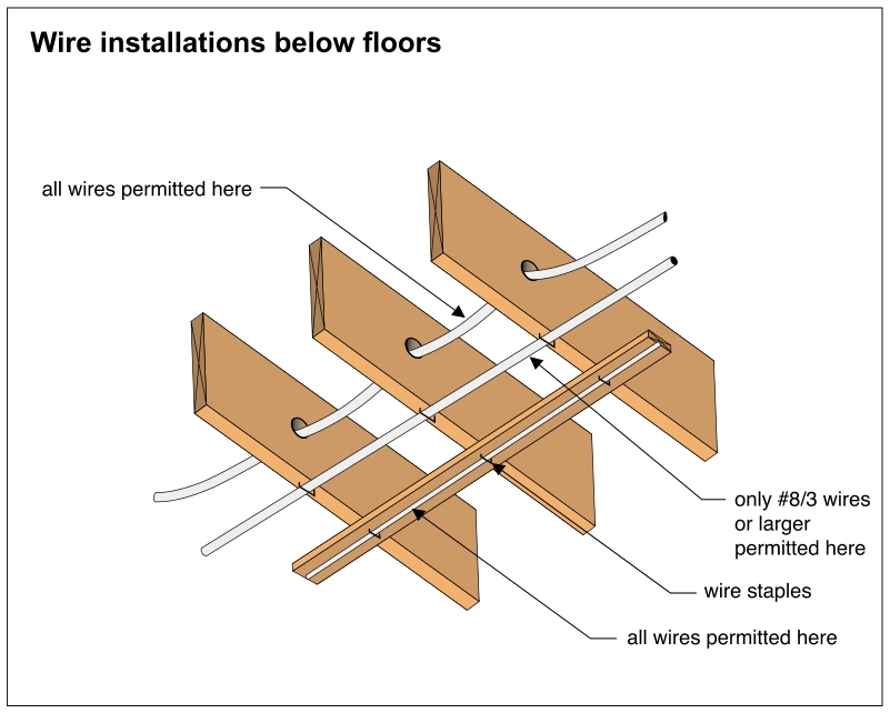
The illustration shows three wiring routes perpendicular to wood floor joists. One cable passes through bored holes in the joists, a location labeled as permitted for all wires. A second cable is stapled directly to the undersides of the joists, with a note limiting this installation to #8/3 wires or larger. A third cable is stapled along a wood running board mounted beneath the joists, also labeled as permitted for all wires.
 0594
0594Wire clearances from hot ducts and pipes
· p. 100
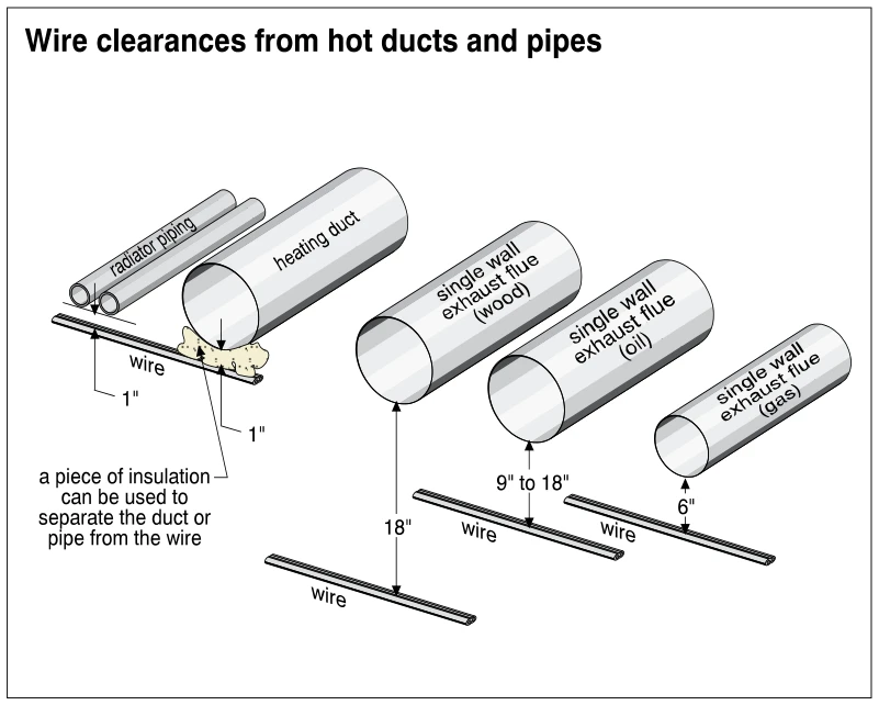
The illustration shows electrical wire clearances from radiator piping, a heating duct, and single-wall exhaust flues serving wood-, oil-, and gas-burning equipment. Radiator piping and the heating duct are shown with 1-inch separation from the wire, with a piece of insulation illustrated between the duct and wire. An annotation states that insulation can be used to separate the duct or pipe from the wire. The depicted wire clearances are 18 inches from the wood exhaust flue, 9 to 18 inches from the oil exhaust flue, and 6 inches from the gas exhaust flue.
The Distribution System ·Knob-and-Tube Wiringp. 101
 0595
0595Edge clearance for wires in studs and joists
· p. 101
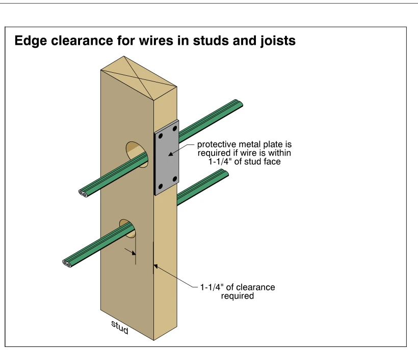
The illustration shows two electrical cables passing through drilled holes in a wood stud. At the upper penetration, a protective metal plate covers the narrow stud face adjacent to the cable. The annotation requires this plate when the wire is within 1-1/4 inches of the stud face. The lower penetration illustrates the required 1-1/4-inch edge clearance without a protective plate.
 0596
0596Wire support with steel studs
· p. 101
The illustration shows electrical wiring passing through and running vertically along a steel stud. A plastic grommet lines the opening where a wire passes through the stud, protecting it from sharp metal edges. Two standoffs support the vertical wire away from the stud face. The annotations specify plastic or wood standoffs that maintain at least 1/4 inch of separation between the wire and metal.
 0597
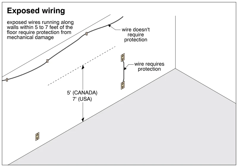
0597Exposed wiring
· p. 101
The illustration shows exposed electrical wiring attached to a wall above a floor. A high horizontal wire run is supported by small fasteners and labeled as not requiring protection. A lower vertical wire run between two wall-mounted electrical devices is labeled as requiring protection from mechanical damage. A dashed height reference identifies the protection zone as within 5 feet of the floor in Canada and 7 feet in the USA.
 0598
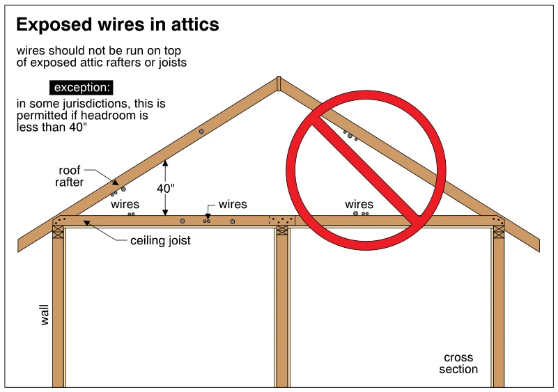
0598Exposed wires in attics
· p. 101
A cross section of a wood-framed attic shows sloped roof rafters, horizontal ceiling joists, supporting walls, and exposed electrical wires. Wire locations are indicated along the rafters and ceiling joists. A large red prohibition symbol emphasizes that wires should not run on top of exposed attic rafters or joists. A vertical 40-inch dimension illustrates headroom between a ceiling joist and a rafter, and an annotation notes that some jurisdictions permit this arrangement where headroom is less than 40 inches.
 0599
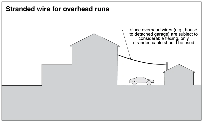
0599Stranded wire for overhead runs
· p. 101
The illustration shows an overhead electrical cable spanning between a house and a detached garage, with a car below the span. The cable sags between its attachment at the house and a vertical support at the garage. The annotation specifies stranded cable for overhead runs because these wires are subject to considerable flexing. No wiring defect is explicitly depicted.
 0600
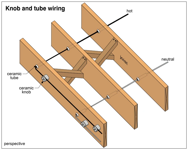
0600Knob and tube wiring
· p. 101
A perspective drawing shows knob-and-tube wiring routed through and along wood floor joists with cross bridging between them. Separate hot and neutral conductors pass through ceramic tubes where they penetrate the joists. Ceramic knobs support the conductors along the face of the nearest joist, keeping them separated from the wood. The illustration identifies the basic wiring components and routing without depicting a specific defect.
The Distribution System ·Lights, Outlets and Switchesp. 102
 0601
0601Knob and tube connections
· p. 102
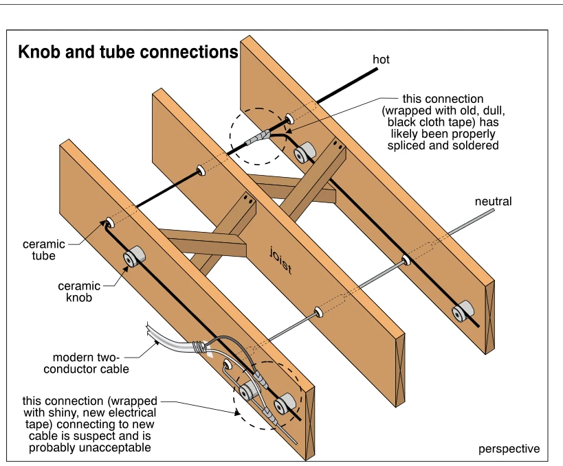
A perspective drawing shows knob-and-tube wiring running through and along wood joists with cross bridging between them. Separate hot and neutral conductors pass through ceramic tubes at joist penetrations and are supported on ceramic knobs along the framing. An upper connection wrapped in old, dull, black cloth tape is identified as likely properly spliced and soldered. A lower connection joins modern two-conductor cable to the existing wiring and is wrapped with shiny, new electrical tape. This newer connection is identified as suspect and probably unacceptable.
 0602
0602Knob and tube wiring - extending a circuit
· p. 102
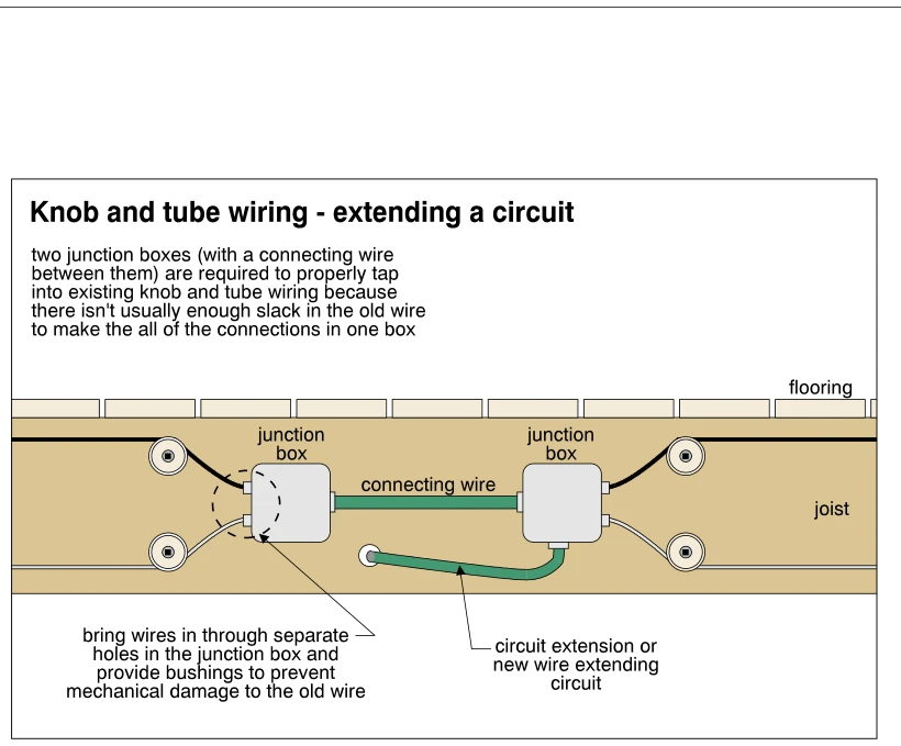
The illustration shows an extension of existing knob-and-tube wiring along a joist beneath flooring. Two junction boxes are linked by a connecting wire, with the existing separate conductors entering the outer sides of the boxes near their insulating knobs. A new circuit-extension cable leaves the right-hand box and passes through the joist. The annotations explain that two boxes accommodate the limited slack in the existing wiring and that old wires should enter through separate holes with protective bushings to prevent mechanical damage.
 0603
0603Fused neutrals in old wiring systems
· p. 102
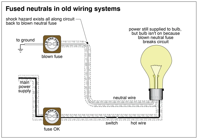
The diagram shows an old lighting circuit with fuses in both the hot and neutral conductors, a switch in the hot conductor, and a light bulb. The hot-side fuse is intact, while the neutral fuse has blown and interrupted the return path to the grounded side of the supply. Although the bulb is not illuminated, power remains supplied to it through the hot conductor. The annotation identifies a shock hazard extending along the circuit back to the blown neutral fuse.
 0604
0604CUAL designation
· p. 102
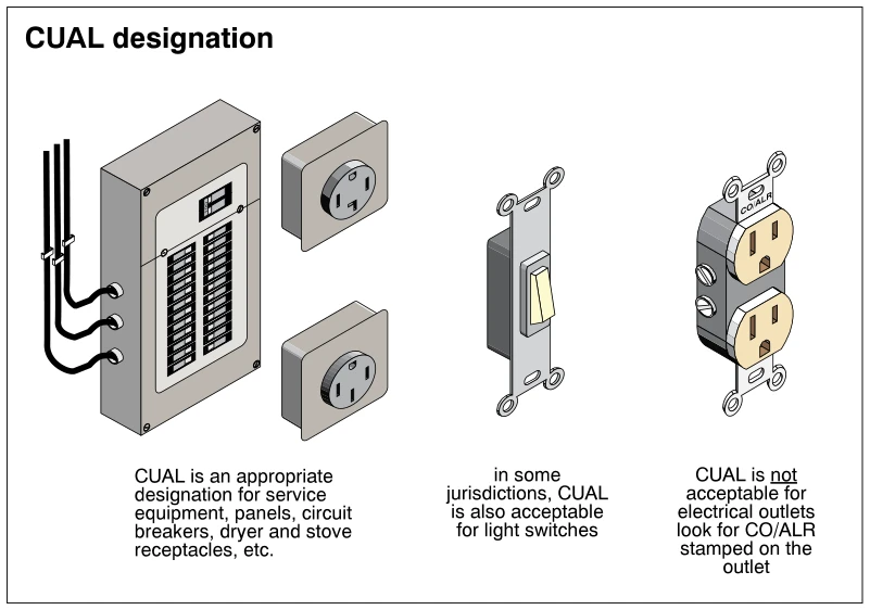
The illustration compares aluminum-wiring compatibility designations for a panel, dryer and stove receptacles, a light switch, and a duplex receptacle. The panel and appliance receptacles are grouped under an annotation identifying CUAL as an appropriate designation for that equipment. The light-switch annotation states that CUAL is acceptable in some jurisdictions. The duplex receptacle is marked CO/ALR, and its annotation states that CUAL is not acceptable for electrical outlets.
 0605
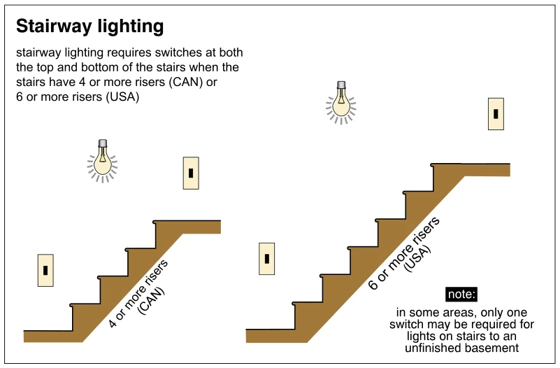
0605Stairway lighting
· p. 102
The illustration shows two stairways in profile, each with a light bulb above the stairs and switches at the top and bottom. The left stairway is labeled for four or more risers in Canada, and the right for six or more risers in the USA. The annotation states that stairway lighting requires switches at both ends for these riser counts. A note identifies a possible local exception allowing only one switch for lights on stairs to an unfinished basement.
 0606
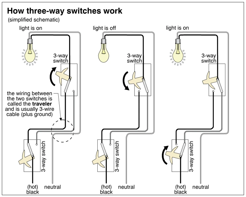
0606How three-way switches work
· p. 102
Three side-by-side simplified schematics show a lamp controlled from two locations by a pair of three-way switches. Each switch selects between two traveler paths, while the neutral connects directly to the lamp. The left diagram shows a completed circuit with the light on; changing the upper switch in the middle diagram opens the circuit and turns the light off. Changing the lower switch in the right diagram completes the alternate path and turns the light on again. Curved arrows indicate switch operation, and a callout identifies the wiring between switches as usually 3-wire cable plus ground.
 0607
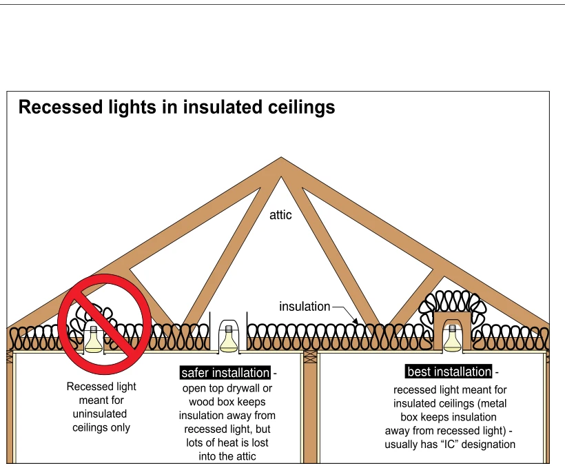
0607Recessed lights in insulated ceilings
· p. 103
A section through an insulated attic floor compares three recessed-light installations beneath roof framing. At left, insulation surrounds a light intended only for uninsulated ceilings, and a red prohibition symbol marks this installation as improper. In the center, an open-top drywall or wood box separates insulation from the fixture; the annotation calls this safer but notes substantial heat loss into the attic. At right, insulation extends over a boxed fixture intended for insulated ceilings, identified as the best installation and usually carrying an “IC” designation.
 0608
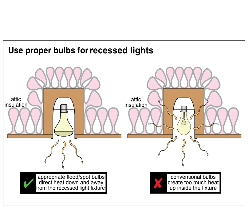
0608Use proper bulbs for recessed lights
· p. 103
The illustration compares bulb types in two recessed ceiling light fixtures surrounded by attic insulation. On the left, a flood/spot bulb is marked with a green check, and arrows show heat directed downward and away from the fixture. On the right, a conventional bulb is marked with a red X, with heat arrows extending upward and sideways inside the fixture as well as downward. The comparison identifies excessive heat inside the recessed fixture as the problem with using a conventional bulb.
 0609
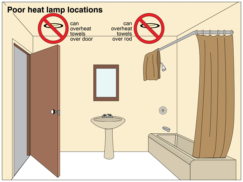
0609Poor heat lamp locations
· p. 103
The illustration shows a bathroom with two ceiling heat lamp locations marked with red prohibition symbols. One lamp is positioned above an open door, where towels draped over the door could overheat. The other is above a shower curtain rod with a towel draped over it, presenting the same overheating concern. A bathtub, shower curtain, shower fittings, pedestal sink, and mirror establish the bathroom setting.
 0609.5
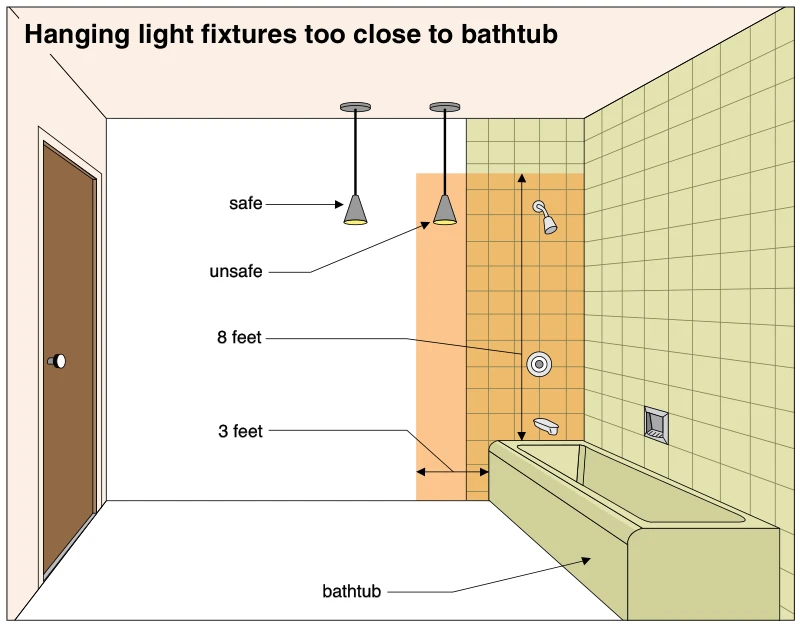
Hanging light fixtures too close to bathtub
· p. 103
The illustration compares safe and unsafe positions for ceiling-hung pendant light fixtures beside a bathtub with a shower. An orange shaded clearance zone extends 3 feet horizontally from the bathtub and 8 feet vertically above the tub rim. One pendant hangs within this zone and is labeled unsafe; another hangs farther from the bathtub, outside the zone, and is labeled safe. The bathroom also shows tiled walls, a showerhead, a shower control, a tub spout, and a recessed wall soap dish.
 0610
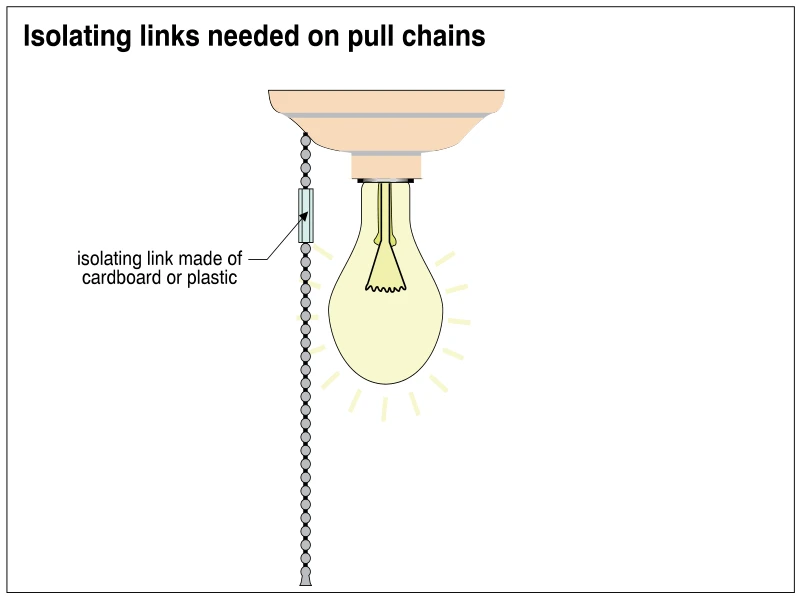
0610Isolating links needed on pull chains
· p. 103
The illustration shows a ceiling-mounted lampholder with an illuminated exposed bulb and a hanging bead pull chain. An isolating link interrupts the chain near the fixture, separating the short upper chain segment from the longer operating segment below. The callout identifies cardboard or plastic as the link material. This depicts the correct use of an insulating break in a light's pull chain to reduce electrical shock risk.
 0611
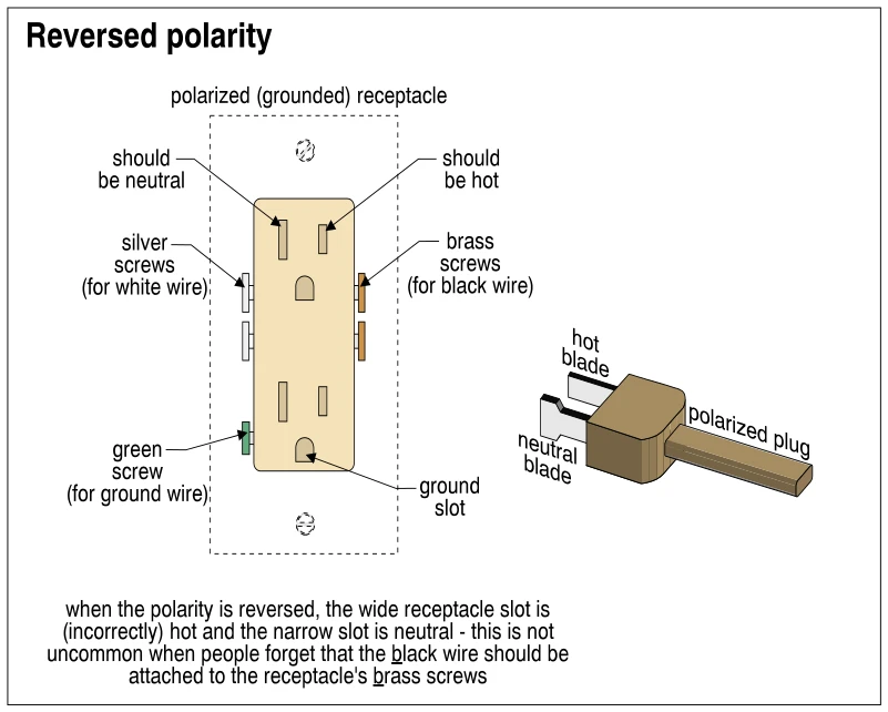
0611Reversed polarity
· p. 103
The illustration shows a grounded duplex receptacle alongside a polarized two-blade plug. Callouts identify the wide receptacle slot as neutral, the narrow slot as hot, and the grounding opening as the ground slot. Silver terminal screws are designated for the white wire, brass terminal screws for the black wire, and a green screw for the ground wire. The plug's hot and neutral blades are also identified. An annotation explains that reversed polarity makes the wide slot hot and the narrow slot neutral; the drawing labels the intended connections rather than showing installed wiring.
 0612
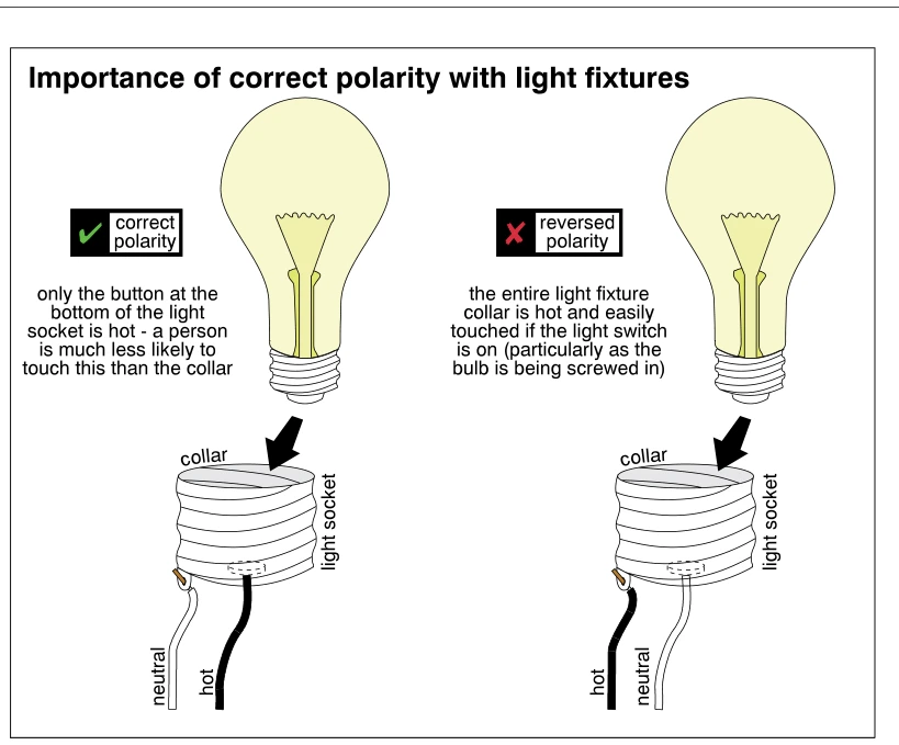
0612Importance of correct polarity with light fixtures
· p. 104
The illustration compares correct and reversed polarity at two screw-base light sockets, with a bulb and insertion arrow above each socket. On the left, a green check identifies correct polarity: the hot conductor connects to the bottom center contact button and the neutral conductor connects to the threaded collar. On the right, a red cross identifies reversed polarity, with the hot conductor connected to the collar and the neutral connected to the bottom contact. The annotations explain that an energized collar is more readily touched than the bottom contact, creating a shock hazard when a bulb is screwed in with the light switch on.
 0612.5
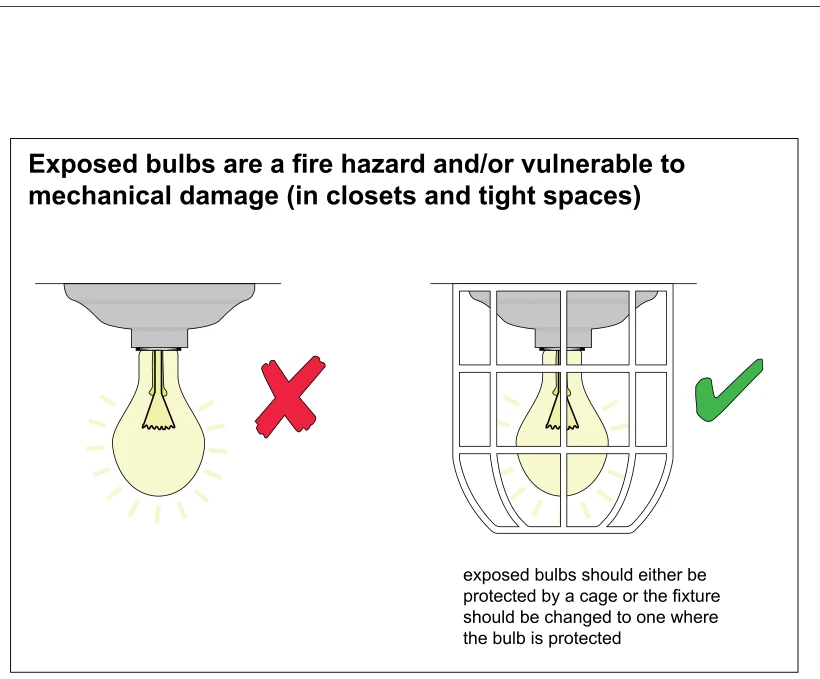
Exposed bulbs are a fire hazard and/or vulnerable to mechanical damage (in closets and tight spaces)
· p. 104
The illustration compares two ceiling-mounted light fixtures with incandescent bulbs. The left fixture has an exposed bulb and is marked with a red X, identifying an improper arrangement in closets and tight spaces where fire hazards or mechanical damage are concerns. The right fixture surrounds the bulb with a protective cage and is marked with a green check. The annotation recommends protecting exposed bulbs with a cage or replacing the fixture with one that protects the bulb.
 0613
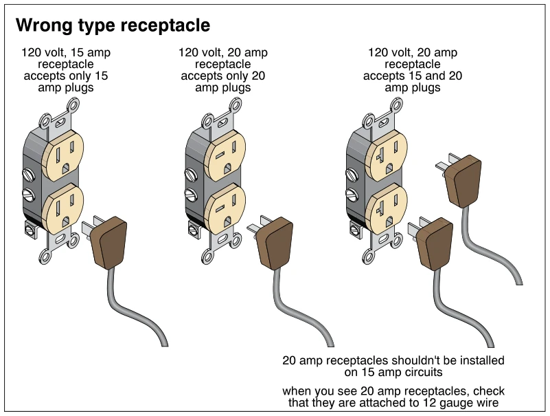
0613Wrong type receptacle
· p. 104
The illustration compares three 120-volt duplex receptacles and their compatible plug blade configurations. The 15-amp receptacle has parallel vertical slots, while the dedicated 20-amp receptacle has one horizontal and one vertical slot. The third receptacle has a T-shaped slot that accepts both 15- and 20-amp plugs. All three receptacles show grounding openings, mounting straps, and side terminal screws. The annotations warn against installing 20-amp receptacles on 15-amp circuits and direct inspectors to check for 12-gauge wire when 20-amp receptacles are present.
 0614
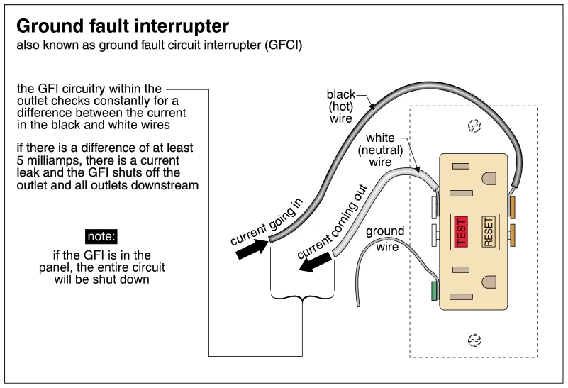
0614Ground fault interrupter
· p. 104
The illustration shows a duplex ground-fault circuit interrupter receptacle with TEST and RESET buttons and connections for hot, neutral, and ground wires. Arrows identify current entering through the black hot wire and returning through the white neutral wire. The annotation explains that internal circuitry continuously compares these currents and shuts off the outlet and downstream outlets if the difference is at least 5 milliamps. A separate note states that a GFI located in the panel shuts down the entire circuit. No installation defect is depicted.
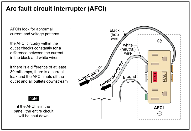 0614.5
Arc fault circuit interrupter (AFCI)
· p. 104
The illustration shows a duplex receptacle labeled AFCI with TEST and RESET buttons and connected hot, neutral, and ground wires. Arrows indicate current entering along the black hot wire and returning along the white neutral wire. The annotations describe monitoring abnormal current and voltage patterns, comparing hot and neutral currents, and shutting off the receptacle and downstream outlets when a specified leakage threshold is reached. A note contrasts this with an AFCI installed in the panel, which shuts down the entire circuit. The current-imbalance and 30-milliamp explanation is presented as printed figure content, rather than a general definition of AFCI arc-detection operation.
 0615
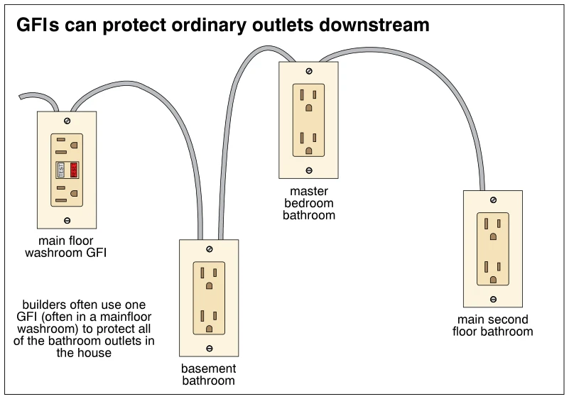
0615GFIs can protect ordinary outlets downstream
· p. 104
The illustration shows a main-floor washroom ground-fault interrupter (GFI) receptacle connected to three ordinary duplex receptacles downstream. The connecting cable path runs to a basement bathroom outlet, then a master bedroom bathroom outlet, and finally a main second-floor bathroom outlet. The GFI receptacle has TEST and RESET buttons, while the downstream receptacles do not. An annotation explains that builders often use one GFI to protect all bathroom outlets in the house; individual terminal connections are not shown.
 0616
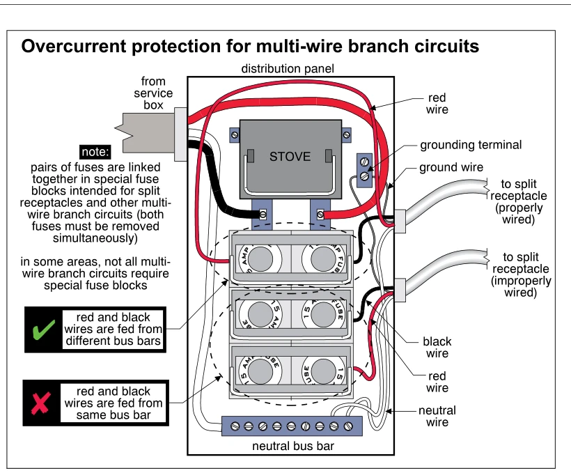
0616Overcurrent protection for multi-wire branch circuits
· p. 105
The illustration shows a fused distribution panel supplying multi-wire branch circuits to split receptacles, with red and black hot conductors, neutral conductors, and a grounding terminal identified. The properly wired circuit takes its red and black feeds from different bus bars, marked with a green check. The improperly wired circuit takes both feeds from the same bus bar, marked with a red cross. A neutral bus bar is shown at the bottom of the panel, and a stove fuse block appears above the branch-circuit fuses. An annotation explains that special linked fuse blocks allow both fuses of a multi-wire branch circuit to be removed simultaneously, while noting that requirements vary by area.
 0617
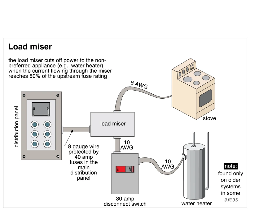
0617Load miser
· p. 105
The diagram shows a load miser connected to a fused distribution panel by 8-gauge wire protected by 40-amp fuses. The load miser supplies a stove through an 8 AWG connection and a water heater through 10 AWG wiring and a 30-amp disconnect switch. The annotation explains that the miser cuts power to the non-preferred appliance, such as the water heater, when current through the miser reaches 80% of the upstream fuse rating. A note identifies this arrangement as found only on older systems in some areas.
 0618
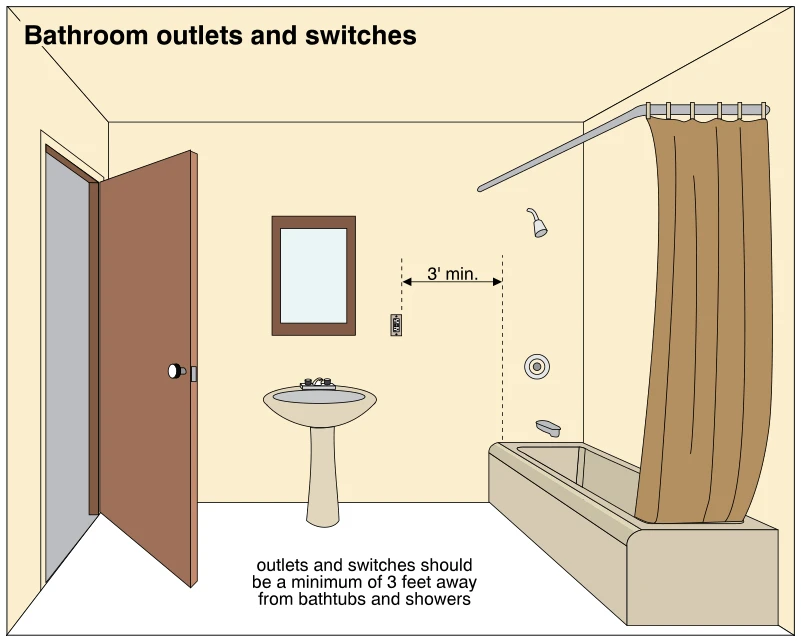
0618Bathroom outlets and switches
· p. 105
The illustration shows a bathroom with a pedestal sink, mirror, and bathtub with a showerhead and curtain. A wall-mounted electrical device is located between the sink and the tub/shower area. A horizontal dimension marks a minimum separation of 3 feet between the electrical device location and the edge of the bathtub/shower area. The annotation presents this separation as the recommended placement for bathroom outlets and switches.
 0619
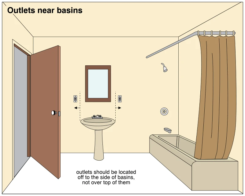
0619Outlets near basins
· p. 105
The illustration shows a bathroom with a pedestal basin, mirror, two wall-mounted electrical receptacles, and a bathtub with shower fittings and a curtain. The receptacles are positioned to either side of the basin rather than directly above it. Dashed vertical lines at the basin edges and outward-pointing arrows emphasize this lateral placement. The annotation states that outlets should be located off to the side of basins, not over them.
 0620
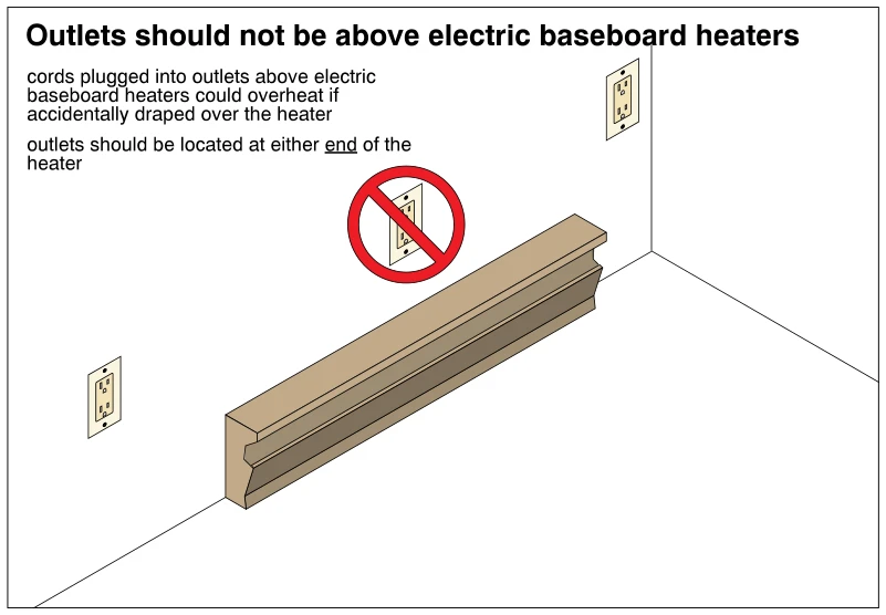
0620Outlets should not be above electric baseboard heaters
· p. 105
The illustration shows a wall-mounted electric baseboard heater with duplex receptacles positioned above it and beyond either end. A red prohibition symbol marks the receptacle directly above the heater as an improper location. The annotations explain that plugged-in cords could overheat if accidentally draped over the heater. Receptacles located at either end of the heater are presented as the preferred arrangement.
 0621
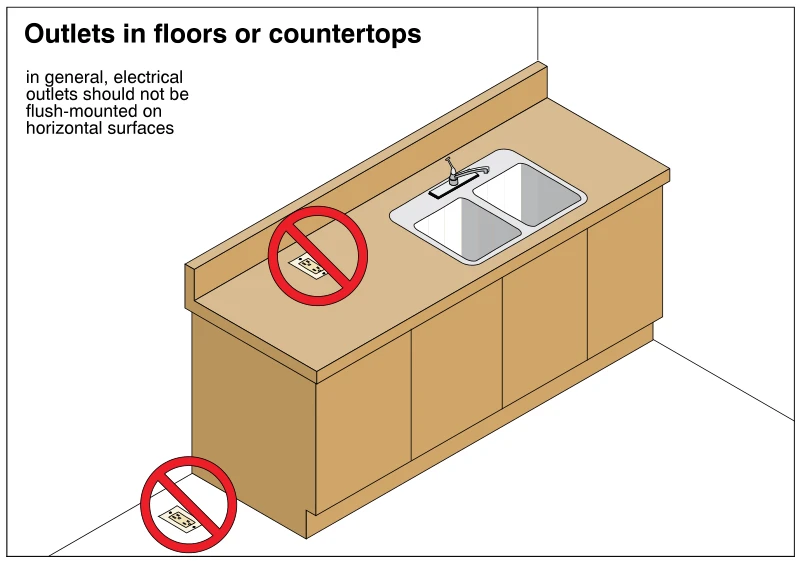
0621Outlets in floors or countertops
· p. 105
The illustration shows a kitchen base cabinet with a countertop, backsplash, double-basin sink, and faucet. One duplex electrical receptacle is flush-mounted face-up in the countertop beside the sink, and another is flush-mounted in the adjacent floor. Red prohibition symbols mark both receptacle locations as improper. The annotation states that, in general, electrical outlets should not be flush-mounted on horizontal surfaces.
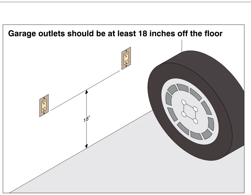 0622
0622Garage outlets should be at least 18 inches off the floor
· p. 106
The illustration shows two duplex electrical receptacles mounted on a garage wall above the floor. A vertical dimension arrow marks 18 inches from the floor to a reference line at the receptacles. A vehicle wheel beside the wall establishes the garage setting. The title identifies mounting garage outlets at least 18 inches above the floor as the recommended practice.
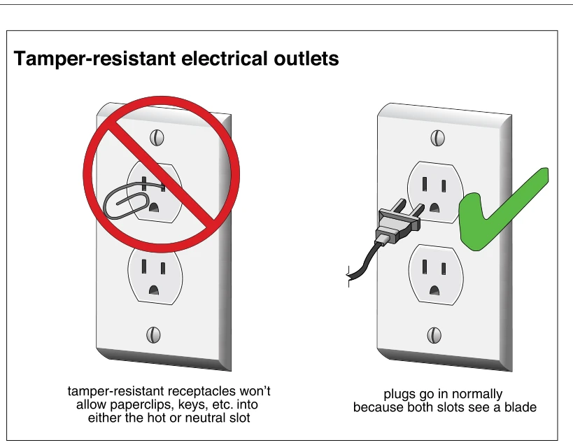 0622.5
Tamper-resistant electrical outlets
· p. 106
The illustration shows two duplex tamper-resistant electrical receptacles with cover plates. On the left, a paperclip is positioned at an upper receptacle beneath a red prohibition symbol, indicating that foreign objects cannot be inserted into either the hot or neutral slot. On the right, a two-blade cord plug is positioned for insertion beside a green check mark. The annotations explain that normal plug insertion is permitted because both slots receive a blade together.
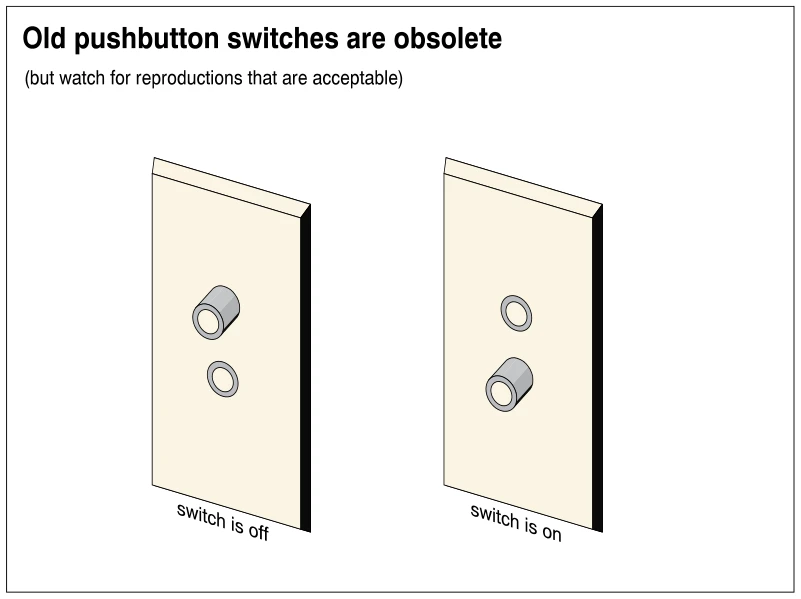 0623
0623Old pushbutton switches are obsolete
· p. 106
The illustration shows two operating states of a two-button electrical wall switch. Each rectangular faceplate has two vertically arranged round pushbuttons. In the off state, the upper button projects outward and the lower button is depressed; in the on state, these positions are reversed. The title identifies old pushbutton switches as obsolete, while the annotation notes that acceptable reproductions exist.
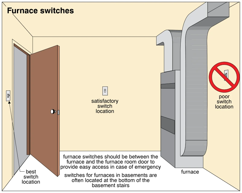 0624
0624Furnace switches
· p. 106
The illustration shows a furnace and connected ductwork in a room with an open entry door, comparing three locations for its electrical shutoff switch. A switch beside the doorway is labeled the best location, while a switch on the wall between the door and furnace is satisfactory. A switch beyond the furnace, away from the doorway, is marked as a poor location with a red prohibition symbol. The annotations explain that furnace switches should be between the furnace and the room door for easy emergency access, and that basement furnace switches are often located at the bottom of the stairs.
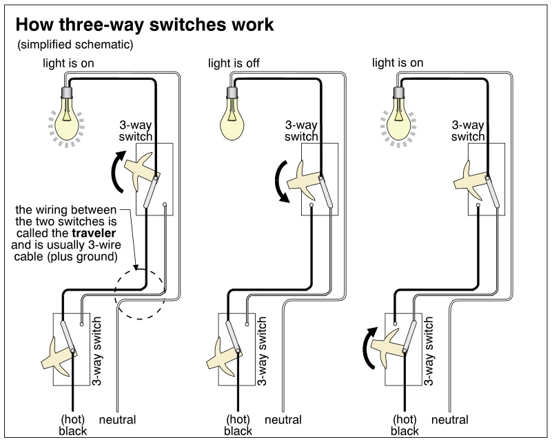 0625
0625How three-way switches work
· p. 106
Three side-by-side simplified schematics illustrate how two three-way switches control a single light. Each circuit shows a black hot feed to the lower switch, traveler conductors between the switches, a switched conductor to the lamp, and a neutral return. The left diagram shows a complete circuit with the light on; operating the upper switch opens the circuit in the middle diagram and turns the light off. Operating the lower switch then completes an alternate traveler path in the right diagram, turning the light on again. Curved arrows indicate switch operation, and a callout identifies the interconnecting traveler wiring as usually three-wire cable plus ground.
 0626
0626Garbage disposal switches
· p. 106
The illustration shows a double-bowl kitchen sink in a countertop above base cabinets, with the garbage disposal identified at one sink drain. A wall switch above the countertop is marked as the best location for disposal control. A dashed switch inside the cupboard below the sink is identified as a better location than the cabinet front. A switch mounted on the front face of the base cabinets is crossed out with a red prohibition symbol because this position leaves it prone to damage.
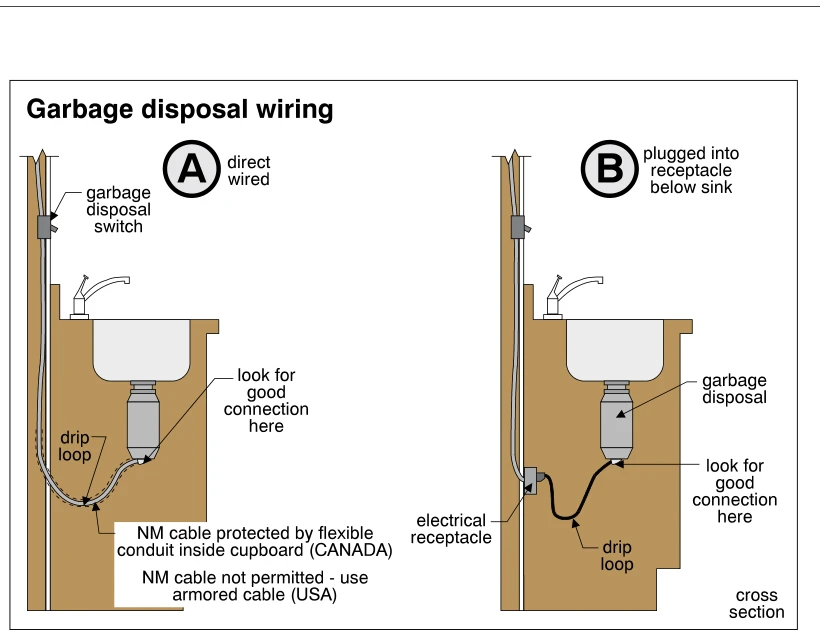 0627
0627Garbage disposal wiring
· p. 107
Two cross-sectional drawings show alternative electrical connections for a garbage disposal beneath a kitchen sink. Detail A shows a wall-switched, directly wired disposal, with the cable protected by flexible conduit inside the cupboard and routed in a drip loop before entering the disposal. An annotation specifies NM cable protected by flexible conduit for Canada and armored cable rather than NM cable for the USA. Detail B shows a disposal plugged into a receptacle below the sink, with a drip loop in its supply cord. Both details direct attention to a good connection at the disposal's electrical entry.