
01Roofing
124 illustrations · printed pages 7-30
Steep Roofing ·Generalp. 8
 0001
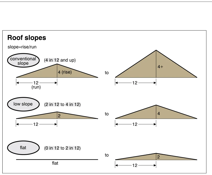
0001Roof slopes
· p. 8
The illustration defines roof slope as vertical rise divided by horizontal run, using schematic roof profiles and dimension arrows. Conventional slopes are labeled as 4 in 12 and up, with the rise measured from the horizontal baseline to the ridge over a 12-unit run. Low slopes are shown ranging from 2 in 12 to 4 in 12. Flat roofs are classified as 0 in 12 to 2 in 12, illustrated by a horizontal line and a shallow pitched profile. No roof coverings, assembly details, or defects are depicted.
 0002
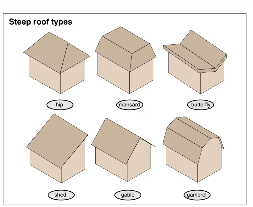
0002Steep roof types
· p. 8
Six simplified perspective drawings show different roof forms on rectangular buildings. The hip roof slopes down toward all sides, while the mansard roof has steep lower slopes and shallower upper slopes. The butterfly roof has two inward-sloping planes meeting at a central valley, and the shed roof has a single sloping plane. The gable roof has two opposing slopes meeting at a ridge, while the gambrel roof has a shallower upper slope and a steeper lower slope on each side. The illustration identifies roof geometries without showing construction details or defects.
 0003
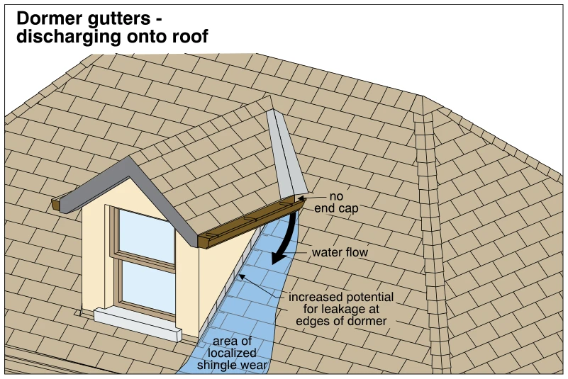
0003Dormer gutters - discharging onto roof
· p. 8
A gabled dormer projects from a larger shingle-covered roof, with a gutter along the dormer's side eave. The gutter has no end cap at its upslope end and discharges directly onto the main roof beside the dormer. An arrow and blue-highlighted strip indicate water flowing downhill alongside the dormer wall. Annotations identify increased potential for leakage at the dormer edges and localized shingle wear in the runoff path.
 0004
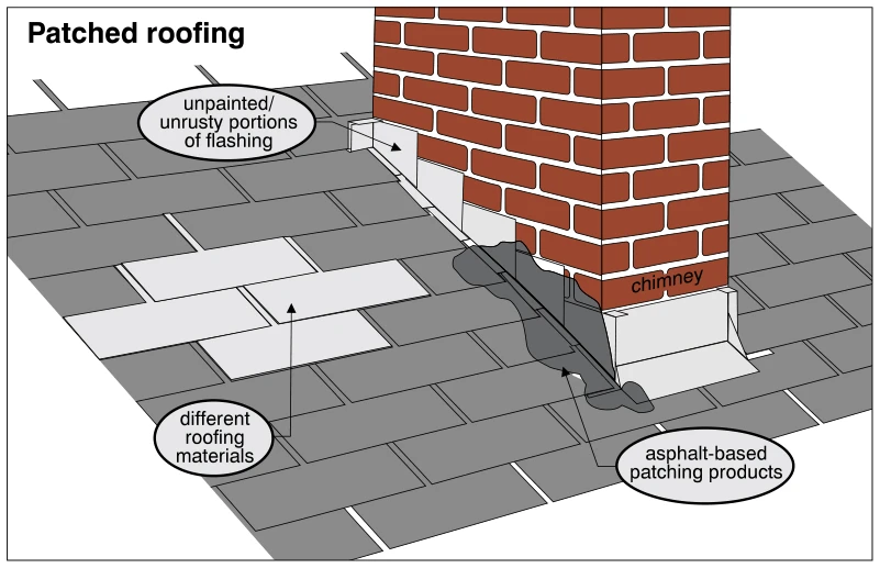
0004Patched roofing
· p. 8
The illustration shows a brick chimney penetrating a sloped roof covered with overlapping rectangular roofing units. Several light-colored roofing units contrast with the surrounding gray covering and are identified as different roofing materials. Metal flashing surrounds the chimney base, with exposed unpainted or unrusty portions called out along one side. Dark asphalt-based patching material covers portions of the roof-to-flashing junction beside the chimney. These contrasting materials and localized applications indicate previous patching at and near the chimney penetration.
 0005
0005Vulnerable areas
· p. 8
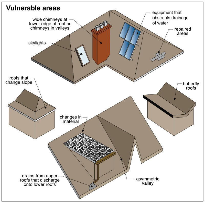
The illustration identifies vulnerable locations on several roof configurations. The upper roof drawing highlights a wide chimney near a valley, a skylight, roof-mounted equipment that obstructs water drainage, and a patched area. Separate examples show a roof with a change in slope and a butterfly roof with inward-sloping planes. The lower drawing highlights a change in roofing material, an upper-roof drain discharging onto a lower roof, and an asymmetric valley. These are identified as areas requiring attention rather than as visible examples of active leakage.
 0006
0006Ice dams
· p. 8
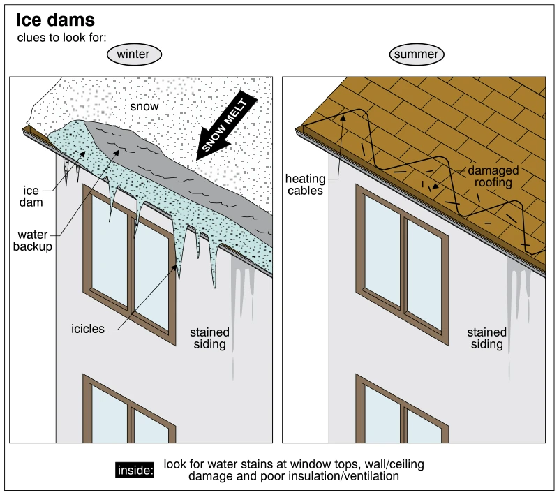
Two views of a roof eave and exterior wall illustrate winter and summer clues associated with ice dams. The winter view shows snowmelt flowing toward an ice dam at the eave, with water backing up behind the ice and icicles hanging over the wall and windows. The summer view shows heating cables arranged along the lower shingle roof and areas labeled as damaged roofing. Both views show stained siding below the eave. An interior inspection note advises looking for water stains at window tops, wall/ceiling damage, and poor insulation/ventilation.
Steep Roofing ·Asphalt Shinglesp. 9
 0007
0007Preventing ice dams with ventilation
· p. 9
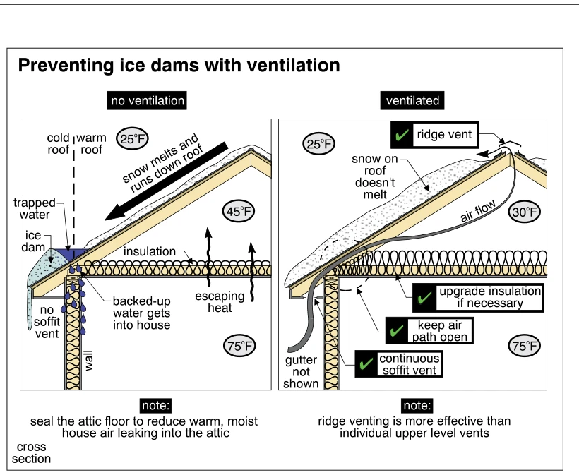
Two roof-and-attic cross sections compare ice-dam formation without ventilation against prevention using soffit-to-ridge ventilation. In the unventilated assembly, escaping house heat warms the attic to 45°F while the exterior is 25°F; snow melts on the warm roof and runoff reaches the cold eave, where an ice dam traps water that backs up into the house. The ventilated assembly shows a continuous soffit vent, an open air path above the insulation, and a ridge vent, with airflow keeping the attic at 30°F and roof snow unmelted. Both examples show a 75°F house interior and insulated ceiling and wall assemblies. Notes recommend sealing the attic floor against warm, moist air leakage, upgrading insulation if necessary, and using ridge venting rather than individual upper-level vents.
 0008
0008Eave protection against ice dams
· p. 9
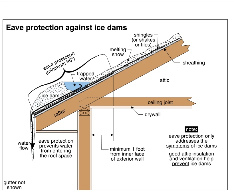
A sectional drawing shows a sloped roof eave supported by a rafter above an exterior wall and ceiling joist. An ice dam at the roof edge traps water from melting snow upslope. Eave protection beneath the roof covering prevents this water from entering the roof space, with an arrow showing drainage down the edge. The protection is labeled as a minimum of 36 inches wide and extending at least 1 foot beyond the inner face of the exterior wall. A note distinguishes this water-entry protection from good attic insulation and ventilation, which help prevent ice dams.
 0009
0009Avalanche guards
· p. 9
The illustration shows tab-type and rail-type avalanche guards on a sloped slate roof. Individual upright tabs project above the overlapping slate courses, while a continuous rail is supported by brackets near the lower edge of the depicted roof. Snow covers the upper roof area, with a large arrow indicating its downslope movement toward the guards. The guards serve to restrain sliding snow, and an annotation notes that they are more common on slate, clay and concrete roofs. No installation defect is identified.
 0010
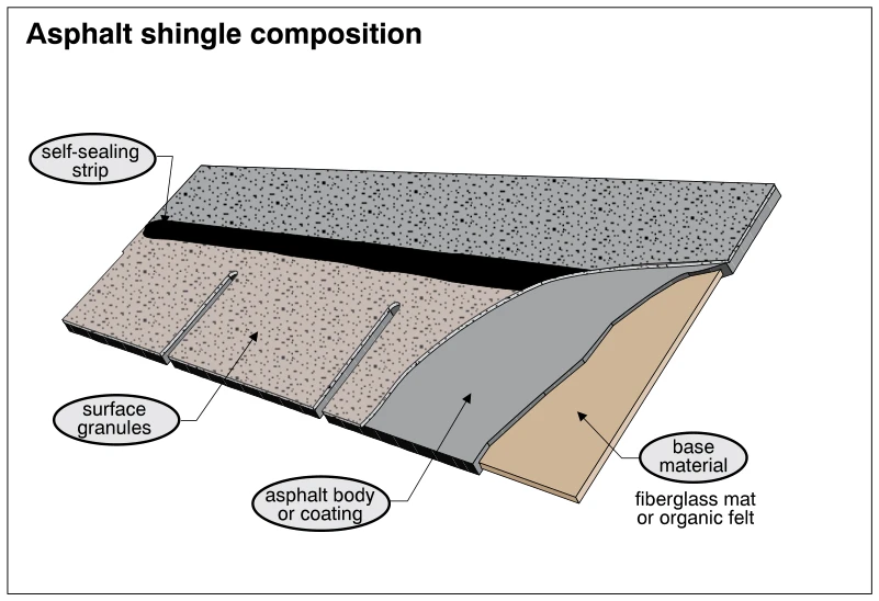
0010Asphalt shingle composition
· p. 9
The illustration shows an asphalt shingle with cutouts defining tabs and a cutaway exposing its constituent layers. Surface granules cover the asphalt body or coating, which overlies a base material identified as fiberglass mat or organic felt. A self-sealing strip runs across the shingle above the tab cutouts. The exposed layers illustrate shingle composition rather than damage or improper installation.
 0010.5
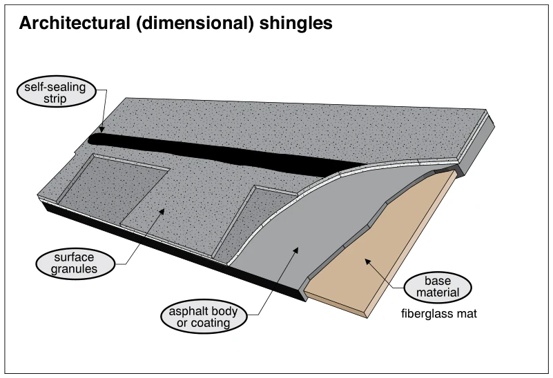
Architectural (dimensional) shingles
· p. 9
The illustration shows an architectural asphalt shingle with a cutaway exposing its material layers. Surface granules cover the asphalt body or coating, which surrounds a fiberglass mat base. Overlapping sections along the exposed edge create the shingle's dimensional profile. A self-sealing strip runs across the upper portion of the shingle. The drawing explains shingle construction rather than depicting an installation defect.
 0011
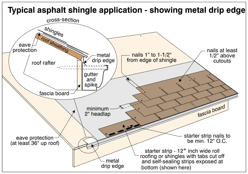
0011Typical asphalt shingle application - showing metal drip edge
· p. 9
The illustration shows a cutaway perspective of a typical asphalt shingle roof application at the eave, with staggered shingle courses installed over eave protection and roof sheathing. An exposed starter strip has self-sealing strips along its bottom edge, and the drawing identifies minimum 2-inch headlap and nail locations relative to shingle edges and cutouts. Eave protection is labeled as extending at least 36 inches up the roof, and metal drip edge runs along the eave above the fascia board. A cross-section inset shows the relationship of shingles, eave protection, sheathing, a roof rafter, fascia, metal drip edge, and a gutter with a spike.
 0012
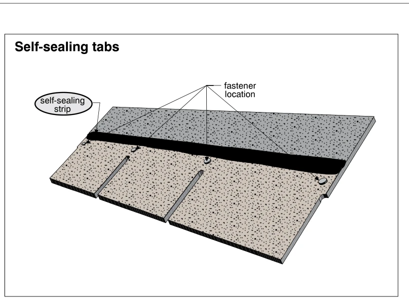
0012Self-sealing tabs
· p. 10
The illustration shows a three-tab asphalt shingle in perspective, with two slots dividing its exposed lower portion into tabs. A continuous dark self-sealing strip runs across the shingle above the slots. Leader arrows identify four fastener locations just below the strip. The drawing identifies the sealing and fastening features without depicting a defect.
 0013
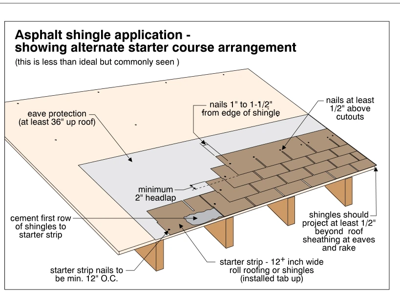
0013Asphalt shingle application - showing alternate starter course arrangement
· p. 10
The illustration shows a cutaway perspective of asphalt shingle installation over roof sheathing, with eave protection beneath the lower courses. An alternate starter strip consists of 12+ inch wide roll roofing or shingles installed tab up; the drawing explicitly describes this arrangement as less than ideal but commonly seen. The first shingle row is cemented to the starter strip, and overlapping courses provide a minimum 2-inch headlap. Nail locations are specified relative to shingle edges and cutouts, with a separate spacing annotation for starter-strip nails. Shingles project at least 1/2 inch beyond the sheathing at both the eaves and rake.
 0014
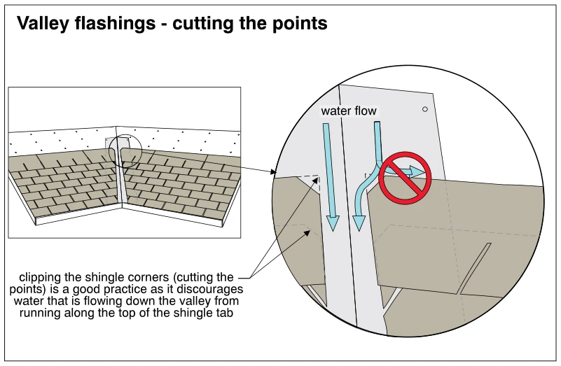
0014Valley flashings - cutting the points
· p. 10
The illustration shows two asphalt-shingled roof slopes meeting at an open, flashed valley, with a magnified detail of the shingle edges. The detail depicts clipping the upper corners of shingles where they border the valley flashing. Blue arrows show water flowing down the valley, while a prohibition symbol marks lateral flow along the top of a shingle tab. Cutting these points discourages valley runoff from being diverted beneath the shingles.
 0015
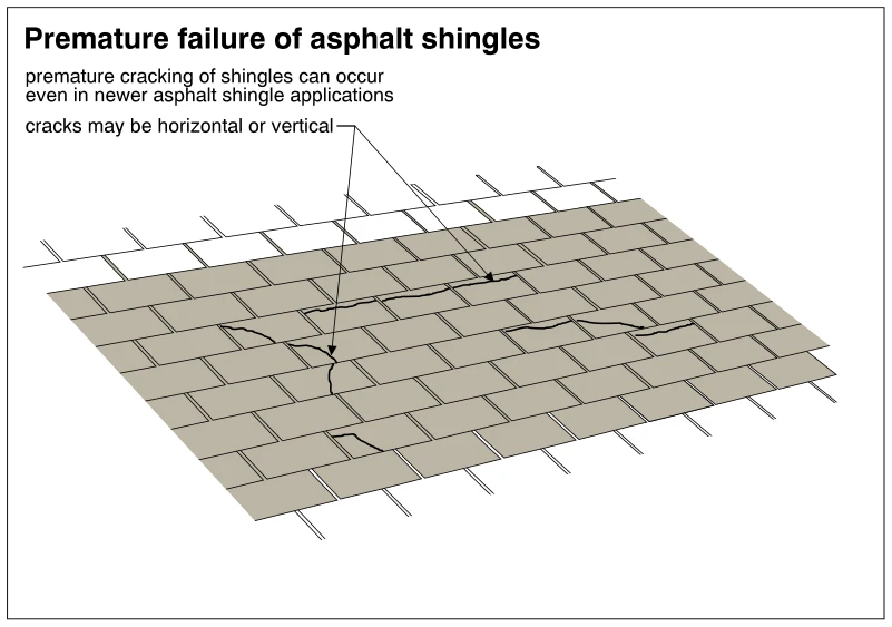
0015Premature failure of asphalt shingles
· p. 10
The illustration shows overlapping courses of asphalt roof shingles with staggered tab joints. Irregular cracks run horizontally and vertically through several shingles, with arrows identifying examples of both orientations. Some cracks extend across multiple adjacent shingle tabs. The annotations identify this as premature failure that can occur even in newer asphalt shingle applications.
 0016
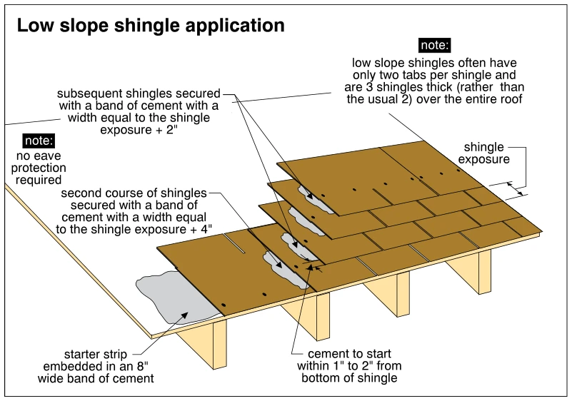
0016Low slope shingle application
· p. 10
The illustration shows a low-slope asphalt shingle roof assembly with successive courses lifted to reveal bands of roofing cement between layers. The starter strip is embedded in an 8-inch-wide band of cement, and the second course uses a band equal to the shingle exposure plus 4 inches. Subsequent courses use a cement band equal to the exposure plus 2 inches, starting within 1 to 2 inches of the shingle bottom. An annotation describes two-tab low-slope shingles with three-shingle thickness over the roof, and another states that no eave protection is required for the illustrated application. The roof deck and supporting wood framing are visible beneath the shingles.
 0017
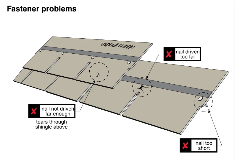
0017Fastener problems
· p. 10
The illustration shows overlapping asphalt shingle courses with three roofing nail installation problems marked by red crosses. An underdriven nail protrudes and tears through the shingle above. An overdriven nail damages the shingle at the fastening point. A third detail identifies a nail that is too short.
Steep Roofing ·Wood Shingles and Shakesp. 11
 0018
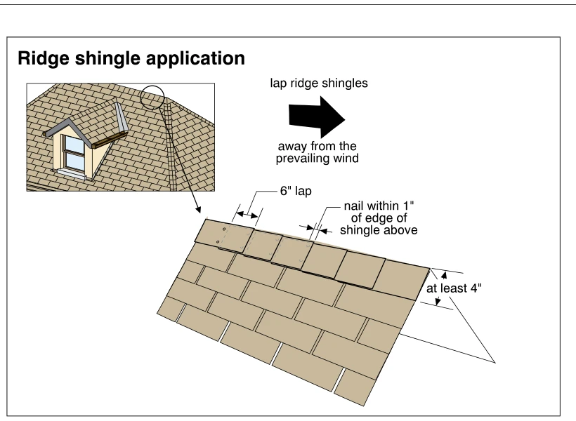
0018Ridge shingle application
· p. 11
The illustration shows overlapping asphalt ridge-cap shingles covering the junction of two roof slopes, with an inset locating the detail on a house roof. An arrow directs that ridge shingles be lapped away from the prevailing wind. The enlarged detail specifies a 6-inch lap and nails within 1 inch of the edge of the shingle above. An end-view dimension indicates that the ridge cap extends at least 4 inches down the roof slope.
 0019
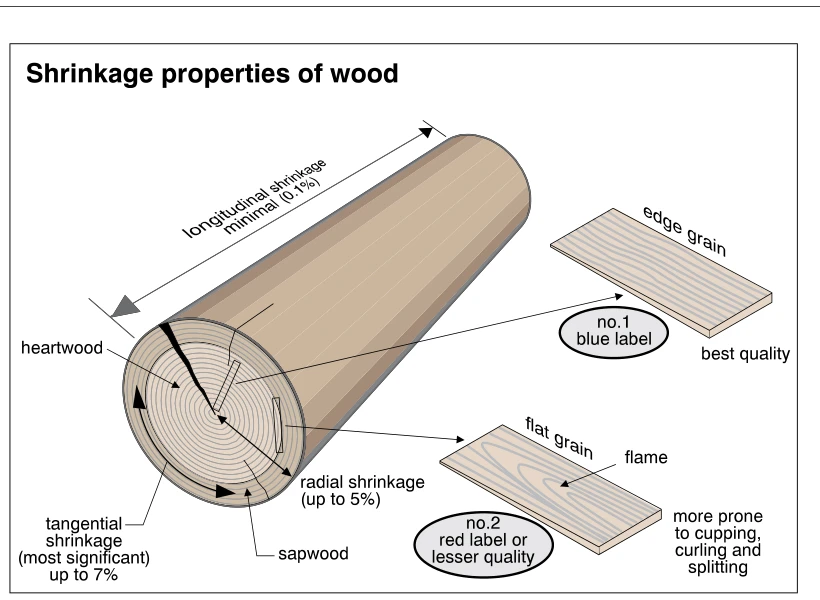
0019Shrinkage properties of wood
· p. 11
The illustration shows a log with exposed growth rings, identifying heartwood and sapwood and the directions of wood shrinkage. Longitudinal shrinkage is labeled minimal at 0.1%, radial shrinkage up to 5%, and tangential shrinkage the most significant at up to 7%. Lines connect the log cross-section to examples of edge-grain and flat-grain wood shingles. The edge-grain example has straight, parallel grain and is labeled no.1 blue label and best quality. The flat-grain example has a flame-shaped grain pattern, is labeled no.2 red label or lesser quality, and is identified as more prone to cupping, curling, and splitting.
 0020
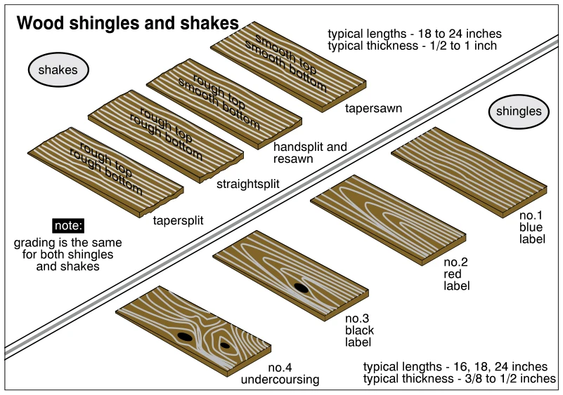
0020Wood shingles and shakes
· p. 11
The illustration presents individual wood shakes and shingles, separated into two groups by a diagonal divider. Four shake types are shown: tapersawn with smooth top and bottom, handsplit and resawn with rough top and smooth bottom, and straightsplit and tapersplit with rough top and bottom. Shake dimensions are listed as typically 18 to 24 inches long and 1/2 to 1 inch thick. Shingles are illustrated in four grades: no.1 blue label, no.2 red label, no.3 black label, and no.4 undercoursing, with varying grain patterns and visible knots in the lower grades. Shingle dimensions are listed as typically 16, 18, or 24 inches long and 3/8 to 1/2 inches thick. A note states that grading is the same for shingles and shakes.
 0021
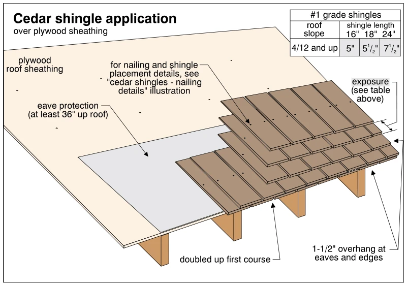
0021Cedar shingle application
· p. 11
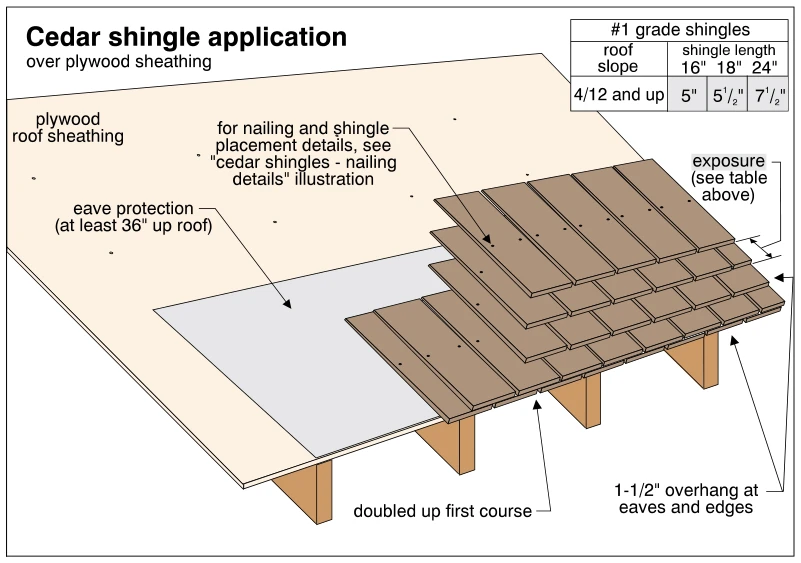
The illustration shows cedar shingles installed in overlapping, staggered courses over plywood roof sheathing, with portions cut away to reveal the underlying assembly. Eave protection extends at least 36 inches up the roof beneath the shingles. The first course is doubled, and shingles overhang the eaves and edges by 1-1/2 inches. A table specifies exposures for #1 grade shingles on roof slopes of 4/12 and up: 5 inches for 16-inch shingles, 5½ inches for 18-inch shingles, and 7½ inches for 24-inch shingles. Visible nail marks accompany a reference to a separate illustration for nailing and shingle placement details.
 0022
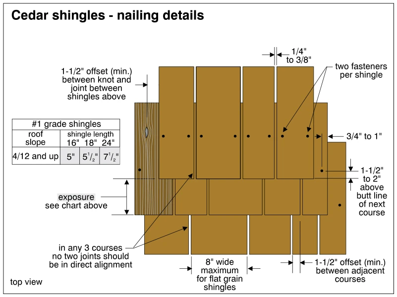
0022Cedar shingles - nailing details
· p. 11
The top-view drawing shows overlapping cedar roof shingle courses with staggered joints and two fasteners per shingle. Fasteners are located 3/4 to 1 inch from the shingle edges and 1-1/2 to 2 inches above the butt line of the next course, with 1/4 to 3/8 inch spacing between shingles. Adjacent courses require at least 1-1/2 inches of joint offset, and no two joints should align within any three courses; a knot must also be offset at least 1-1/2 inches from the joint between shingles above. Flat-grain shingles are limited to 8 inches in width. A table specifies exposures of 5, 5½, and 7½ inches for #1 grade shingles of 16, 18, and 24 inches in length, respectively, on roof slopes of 4/12 and up.
 0023
0023Cedar shingle application- spaced plank sheathing
· p. 11
The illustration shows overlapping cedar shingle courses installed over spaced 1x4 or 1x6 plank roof sheathing supported by rafters. Continuous decking at the eaves supports an eave-protection layer extending at least 36 inches up the roof beneath the shingles. The first shingle course is doubled, with a specified 1-1/2-inch overhang at the eaves and edges. A table specifies exposures for #1 grade shingles on roof slopes of 4/12 and up: 5 inches for 16-inch shingles, 5½ inches for 18-inch shingles, and 7½ inches for 24-inch shingles. The drawing refers to a separate illustration for nailing and shingle-placement details.
 0024
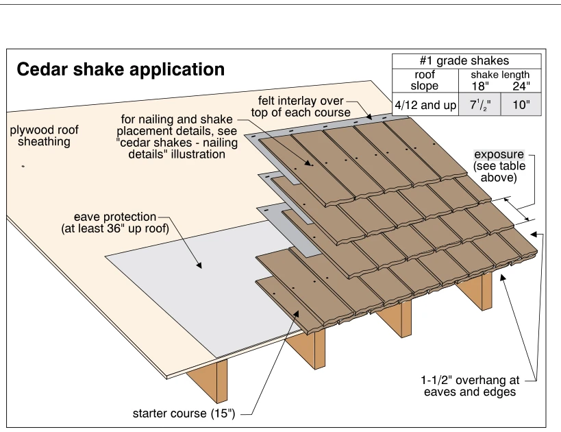
0024Cedar shake application
· p. 12
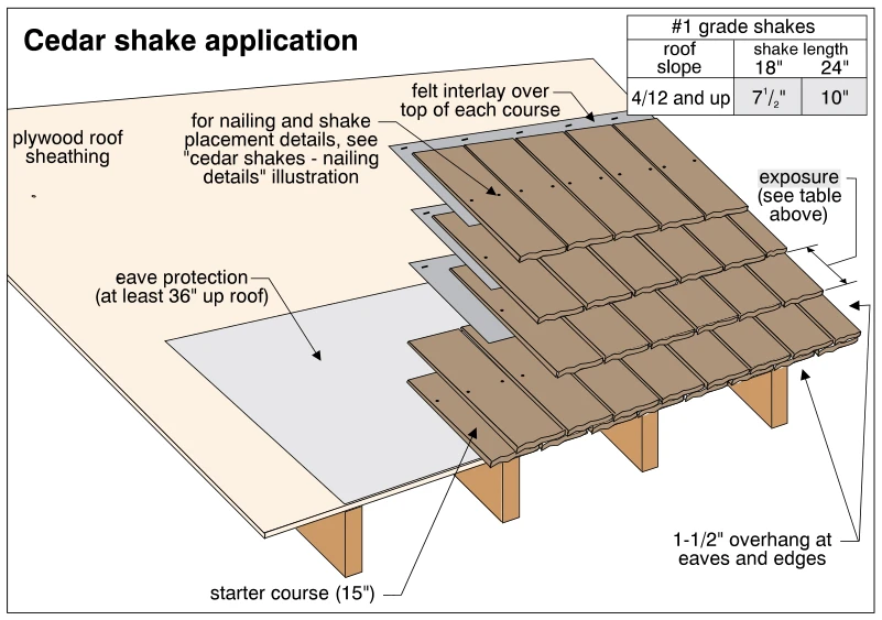
The illustration shows a cutaway cedar shake roof assembly over plywood sheathing, with overlapping shake courses and felt interlay over the top of each course. Eave protection extends at least 36 inches up the roof beneath a 15-inch starter course. The shakes project 1-1/2 inches beyond the eaves and edges. A table specifies exposures for #1 grade shakes on slopes of 4/12 and up: 7-1/2 inches for 18-inch shakes and 10 inches for 24-inch shakes. The drawing directs the reader to a separate illustration for nailing and shake placement details.
 0025
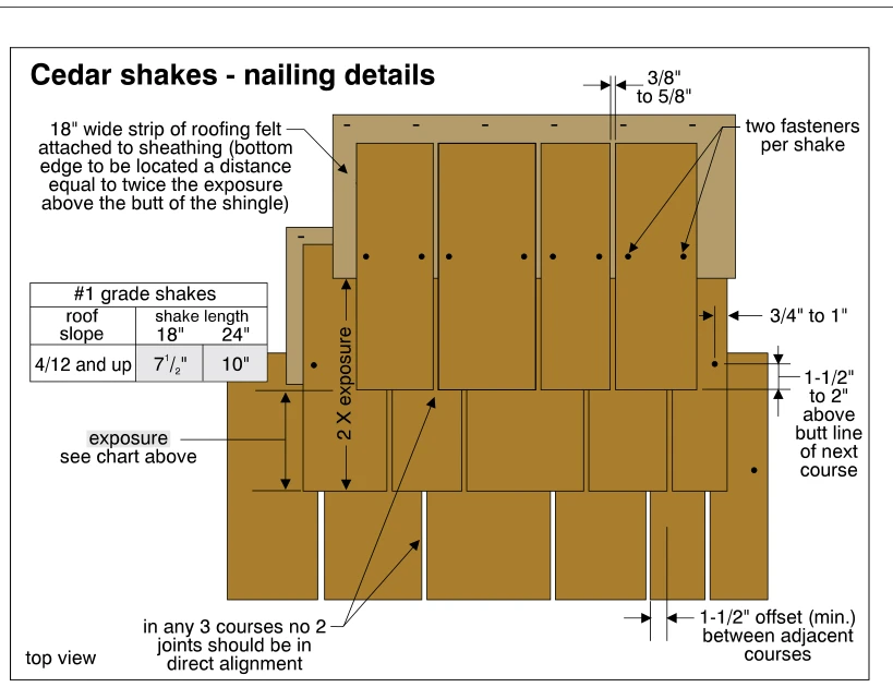
0025Cedar shakes - nailing details
· p. 12
The illustration shows a top view of overlapping cedar shake roofing courses with roofing felt interlaid and attached to the sheathing. Each shake receives two fasteners, located 3/4 to 1 inch from its side edges and 1-1/2 to 2 inches above the butt line of the next course. Shakes are spaced 3/8 to 5/8 inch apart, with joints offset at least 1-1/2 inches between adjacent courses and no two joints directly aligned within any three courses. The bottom edge of the 18-inch-wide felt strip is positioned twice the exposure above the shake butt. A table specifies exposures for #1 grade shakes on slopes of 4/12 and up: 7½ inches for 18-inch shakes and 10 inches for 24-inch shakes.
 0026
0026Cedar shake application
· p. 12
The illustration shows cedar shakes installed in overlapping courses over plywood roof sheathing, with portions exposed to reveal the underlying layers. Felt interlay extends over the top of each course, and eave protection extends at least 36 inches up the roof. A 15-inch starter course is shown beneath the first course, with a specified 1-1/2-inch overhang at eaves and edges. The table specifies exposures for #1 grade shakes on roof slopes of 4/12 and up: 7½ inches for 18-inch shakes and 10 inches for 24-inch shakes.
 0027
0027Cedar shingle application
· p. 12
The illustration shows overlapping courses of cedar shingles installed over plywood roof sheathing supported by wood framing. Eave protection extends at least 36 inches up the roof beneath the shingles. The first course is doubled, and shingles overhang the eaves and edges by 1-1/2 inches. A table specifies exposures for #1 grade shingles on slopes of 4/12 and up: 5 inches for 16-inch shingles, 5½ inches for 18-inch shingles, and 7½ inches for 24-inch shingles. Nail locations are indicated, with a reference to a separate illustration for nailing and shingle placement details.
 0028
0028Cedar shingle application- using synthetic ventilation layer
· p. 12
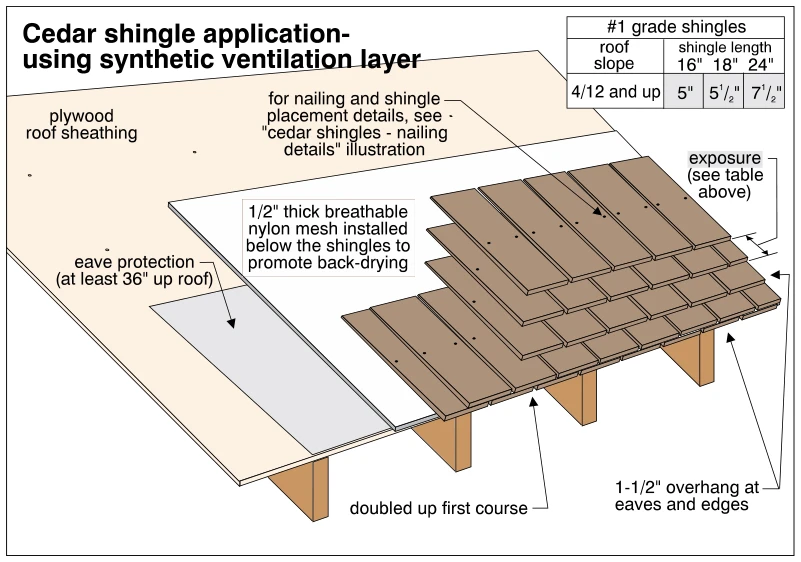
The illustration shows a cutaway cedar shingle roof assembly over plywood roof sheathing, with eave protection extending at least 36 inches up the roof. A 1/2-inch-thick breathable nylon mesh layer beneath the shingles promotes back-drying. The shingles are installed in overlapping courses with staggered joints, a doubled first course, and a 1-1/2-inch overhang at eaves and edges. A table specifies exposures for #1 grade shingles on slopes of 4/12 and up: 5 inches for 16-inch shingles, 5-1/2 inches for 18-inch shingles, and 7-1/2 inches for 24-inch shingles. An annotation directs readers to a separate illustration for nailing and shingle placement details.
 0029
0029Curling, cupping and splitting wood shingles
· p. 12
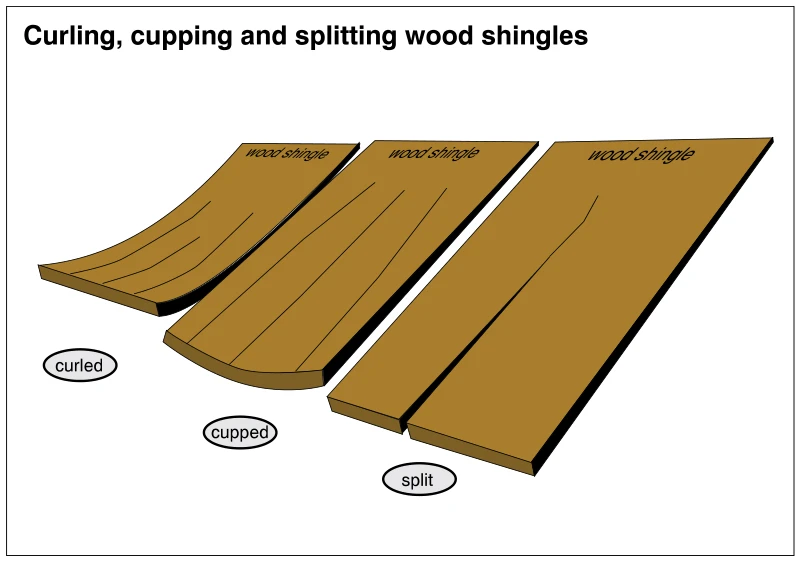
Three individual wood roofing shingles illustrate curling, cupping and splitting. The left shingle curves along its length, lifting its exposed end. The middle shingle is cupped across its width, with raised sides relative to its center. The right shingle has a lengthwise split extending inward from the butt edge. These are examples of wood-shingle distortion and damage, rather than an installed roof assembly.
Steep Roofing ·Slatep. 13
 0030
0030Slate types
· p. 13
The illustration presents three individual roofing slates labeled Pennsylvania, Vermont, and Buckingham (Virginia). Each rectangular slate is drawn with layered edges and two fastening holes. The annotations give typical service lives of 35 to 75 years for Pennsylvania slate, 100 years for Vermont slate, and 175 years for Buckingham slate. Color descriptions distinguish the blue-grey to black Pennsylvania varieties, the broader color range of Vermont slate, and the blue-grey to dark grey Buckingham slate with unusual luster. No installation assembly or defects are depicted.
 0031
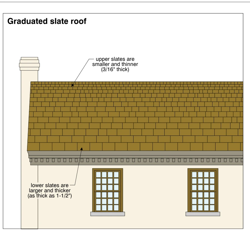
0031Graduated slate roof
· p. 13
The illustration shows a graduated slate roof on a house elevation with a chimney, eave trim, and two windows. The slate courses have staggered joints and progressively smaller exposed units toward the top of the roof. Upper slates are labeled as smaller and thinner, at 3/16 inch thick, while lower slates are larger and thicker, reaching 1-1/2 inches thick. The drawing explains the graduated arrangement rather than depicting a defect.
 0032
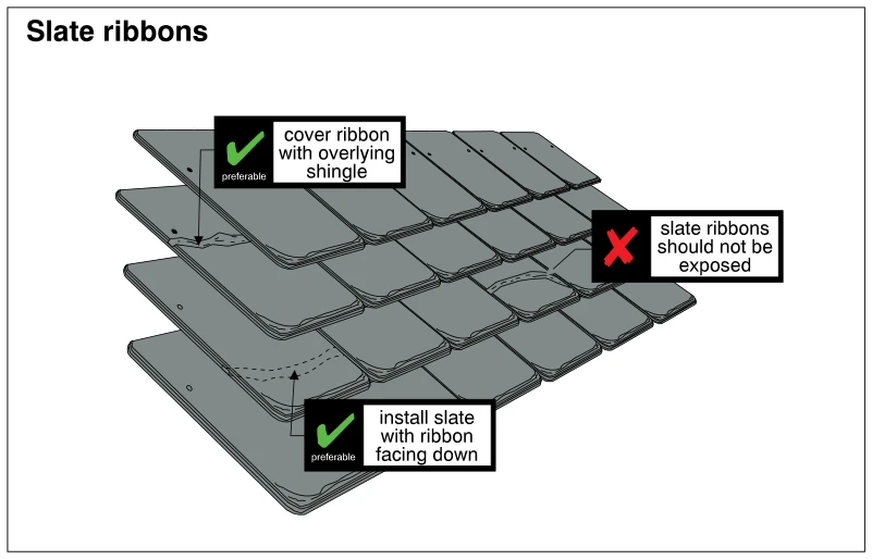
0032Slate ribbons
· p. 13
The illustration shows overlapping courses of slate roofing with ribbon-like bands in individual slates. A green check identifies a ribbon covered by an overlying shingle as preferable. Another green check indicates installing slate with the ribbon facing down, illustrated by a dashed band. A red X marks a ribbon exposed on the weather-facing surface as improper.
 0033
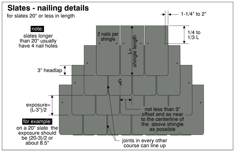
0033Slates - nailing details
· p. 13
The illustration shows overlapping courses of slate roofing with staggered vertical joints and two nails per shingle for slates 20 inches or less in length. Nail holes are located 1-1/4 to 2 inches inward from the side edges and one-quarter to one-third of the shingle length below the top. A 3-inch headlap is shown, with exposure calculated as (shingle length minus 3 inches) divided by two, giving about 8.5 inches for a 20-inch slate. Joints in adjacent courses are offset at least 3 inches and positioned as near as possible to the centerline of the slate above; joints in every other course may align. A note states that slates longer than 20 inches usually have four nail holes.
 0034
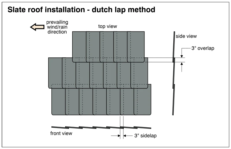
0034Slate roof installation - dutch lap method
· p. 13
The illustration shows the Dutch lap method of slate roofing installation in top, side, and front views. The top view depicts three courses of rectangular slates with overlapping side edges and dashed lines indicating concealed edges. The side view identifies a 3-inch overlap between courses, while the front view identifies a 3-inch sidelap between adjacent slates. An arrow indicates the prevailing wind/rain direction relative to the lap arrangement.
 0035
0035Slate roof installation - french method
· p. 13
The illustration shows slate roofing installed using the French method, with square slates oriented diagonally in overlapping, staggered courses. Two adjacent sides of a typical slate are dimensioned 12–14 inches, and its downward-facing corner is clipped. A callout identifies a 3-inch lap between slates. Starter slates form a straight lower roof edge, while dashed lines indicate concealed slate edges beneath subsequent courses.
Steep Roofing ·Clayp. 14
 0036
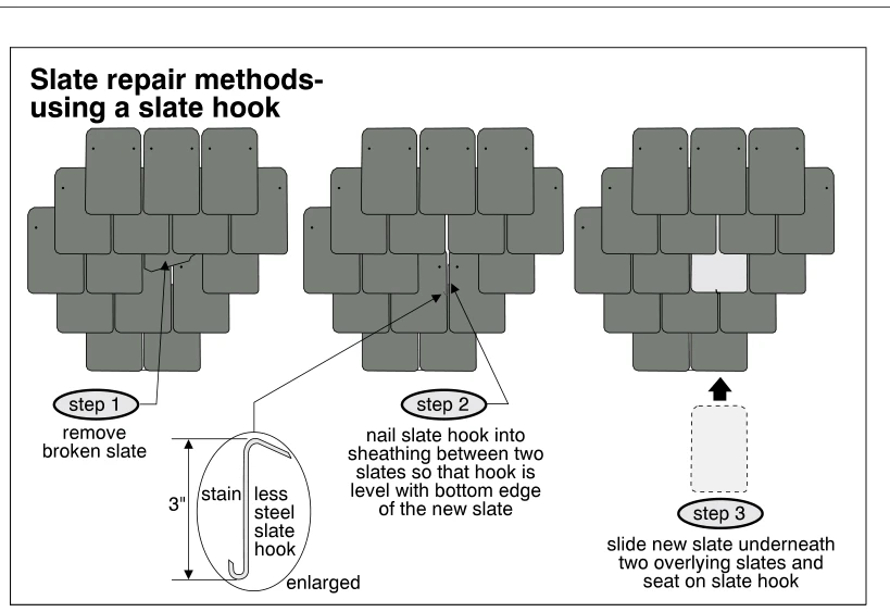
0036Slate repair methods- using a slate hook
· p. 14
The illustration shows a three-step repair of an overlapping slate roof using a slate hook. First, the broken slate is removed. A stainless steel hook is then nailed into the sheathing between two slates, with its lower hook positioned level with the bottom edge of the replacement slate. An enlarged detail shows the hook's bent upper end and upturned lower end, with a 3-inch dimension. Finally, the new slate slides beneath two overlying slates and seats on the hook.
 0037
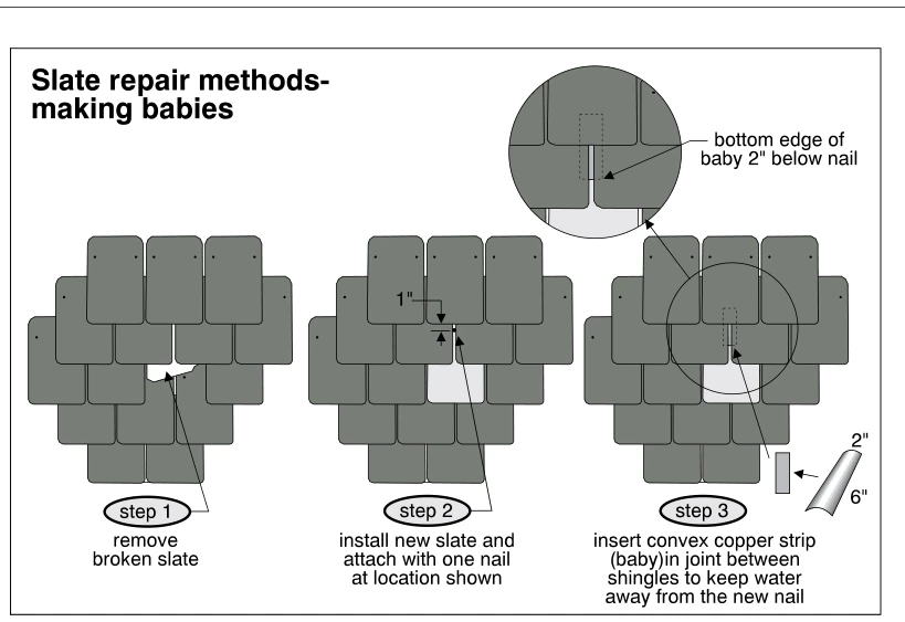
0037Slate repair methods- making babies
· p. 14
The illustration shows a three-step repair of an overlapping slate roof using a copper strip called a baby. First, the broken slate is removed; then a replacement slate is installed and attached with one nail at the indicated location, with a 1-inch placement dimension shown. A convex copper strip, illustrated as 2 inches wide and 6 inches long, is inserted into the joint between the overlying slates to divert water away from the new nail. An enlarged detail shows the concealed strip and specifies that its bottom edge extends 2 inches below the nail.
 0038
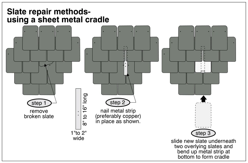
0038Slate repair methods- using a sheet metal cradle
· p. 14
The illustration shows a three-step repair of overlapping slate roofing using a sheet metal cradle. First, the broken slate is removed from the staggered courses. A metal strip, preferably copper, is then nailed in place at the opening; the strip is specified as 8 to 16 inches long and 1 to 2 inches wide. The replacement slate slides underneath two overlying slates, and the bottom of the metal strip is bent upward to form a cradle that supports its lower edge.
 0039
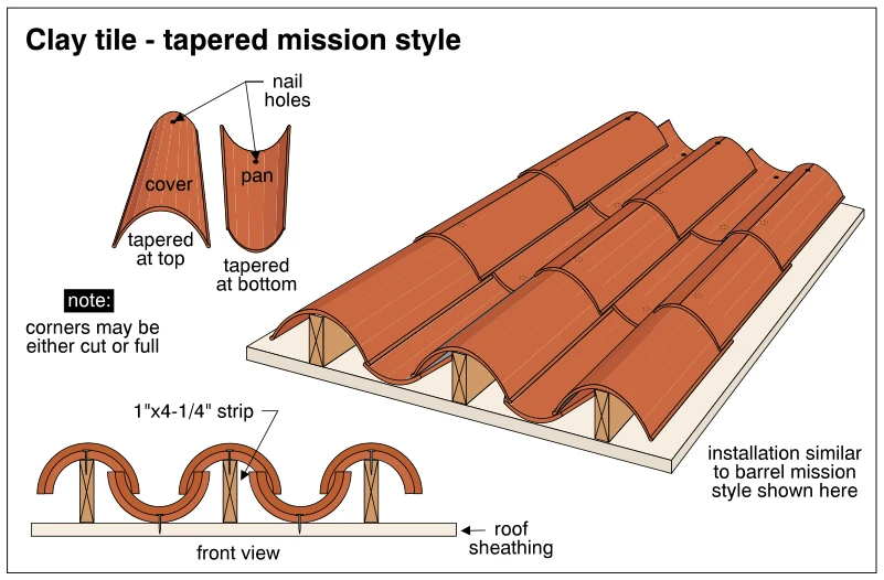
0039Clay tile - tapered mission style
· p. 14
The illustration shows tapered mission-style clay roofing tiles, with separate convex cover tiles and concave pan tiles. Detail views identify nail holes and show the cover tapered at the top and the pan tapered at the bottom. A perspective installation view shows overlapping courses, with covers bridging the joints between adjacent pans. The front view shows wood strips supporting the covers above the roof sheathing, with the pans forming channels between them. Notes state that tile corners may be cut or full and that installation is similar to the barrel mission style shown.
 0040
0040Clay tile - barrel mission style (straight)
· p. 14
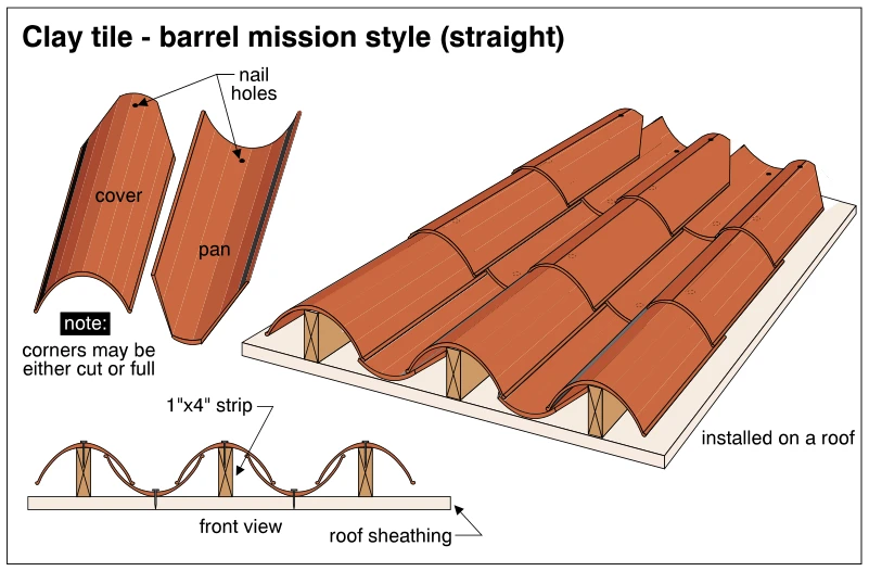
The illustration shows straight barrel mission-style clay roof tiles, with separate curved cover and pan pieces and their nail holes identified. Concave pan tiles form drainage channels, while convex cover tiles bridge the joints between adjacent pans. A perspective view shows successive tiles overlapping along the roof slope. The front view shows the cover tiles supported over upright 1-by-4-inch strips on roof sheathing, with the pans resting between them. A note indicates that tile corners may be either cut or full.
 0041
0041Clay tile - "S" style
· p. 14
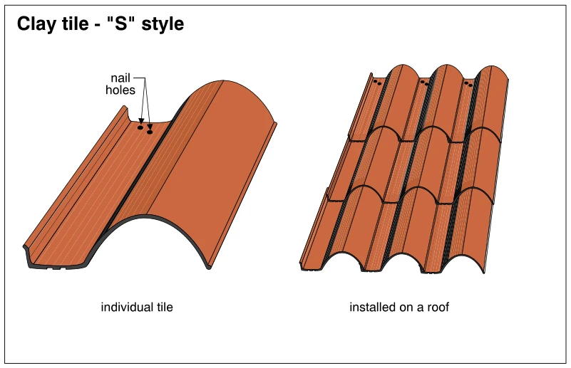
The illustration shows an individual S-style clay roof tile alongside an assembled section of tile roofing. Each tile combines a concave channel with a raised convex barrel, forming an S-shaped profile. Two nail holes are identified near the upper end of the individual tile. The installed view shows tiles arranged side by side in overlapping courses, creating continuous alternating channels and rounded ridges. No defects are depicted.
Steep Roofing ·Concrete and Fiber Cementp. 15
 0042
0042Clay tile - interlocking shingle
· p. 15
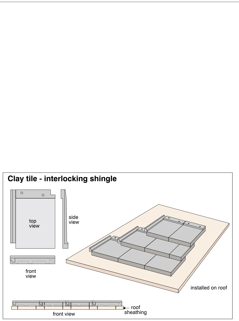
The illustration shows interlocking shingle-style clay roof tiles in top, side, and front views, together with an installed perspective view. Individual tiles have flat faces, shaped interlocking side edges, and two holes near the upper edge. The installed view shows overlapping courses with staggered joints on roof sheathing. A lower front view illustrates how adjacent tile edges interlock above the sheathing. No defects or improper installation practices are indicated.
 0043
0043How clay tiles are secured
· p. 15
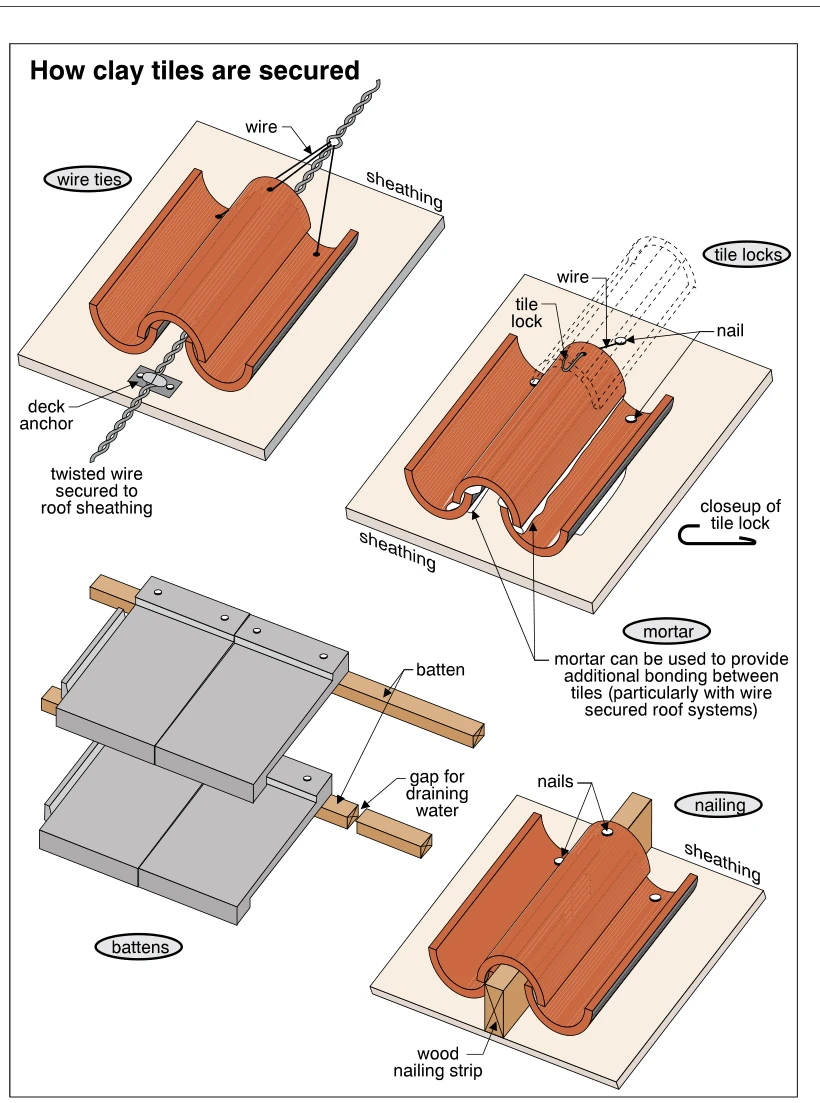
The illustration shows several methods for securing clay roof tiles: wire ties, tile locks, mortar, battens, and nailing. The wire-tie detail shows tiles connected to twisted wire secured to roof sheathing by a deck anchor, while the tile-lock detail includes a wire, nail, and enlarged view of the lock. Mortar is shown at tile contact areas to provide additional bonding, particularly with wire-secured systems. A separate detail shows overlapping flat tiles supported on battens, with a gap in a batten for draining water. The nailing detail shows a profiled tile over sheathing and a wood nailing strip, with nails positioned near the tile's upper end.
 0045
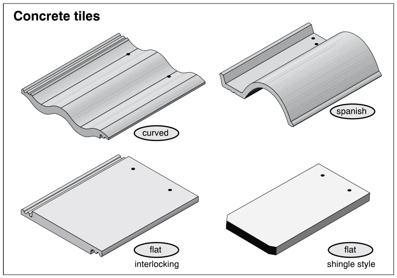
0045Concrete tiles
· p. 15
The illustration shows four concrete roof tile profiles in perspective: curved, Spanish, flat interlocking, and flat shingle style. The curved tile has an undulating profile, while the Spanish tile combines a broad rounded roll with an adjacent channel. The flat interlocking tile has molded side-edge grooves and ribs, whereas the flat shingle-style tile has plain edges. Each example shows two fastening holes near its upper end. No installed assembly or defects are depicted.
 0044
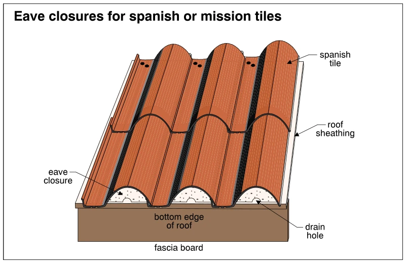
0044Eave closures for spanish or mission tiles
· p. 15
The illustration shows overlapping Spanish or mission roof tiles installed over roof sheathing at an eave. Shaped eave closures fill the arched openings beneath the raised portions of the tiles at the bottom edge of the roof. Small drain holes are shown at the bases of the closures. A fascia board runs across the roof edge below the tile ends.
Steep Roofing ·Metalp. 16
 0046
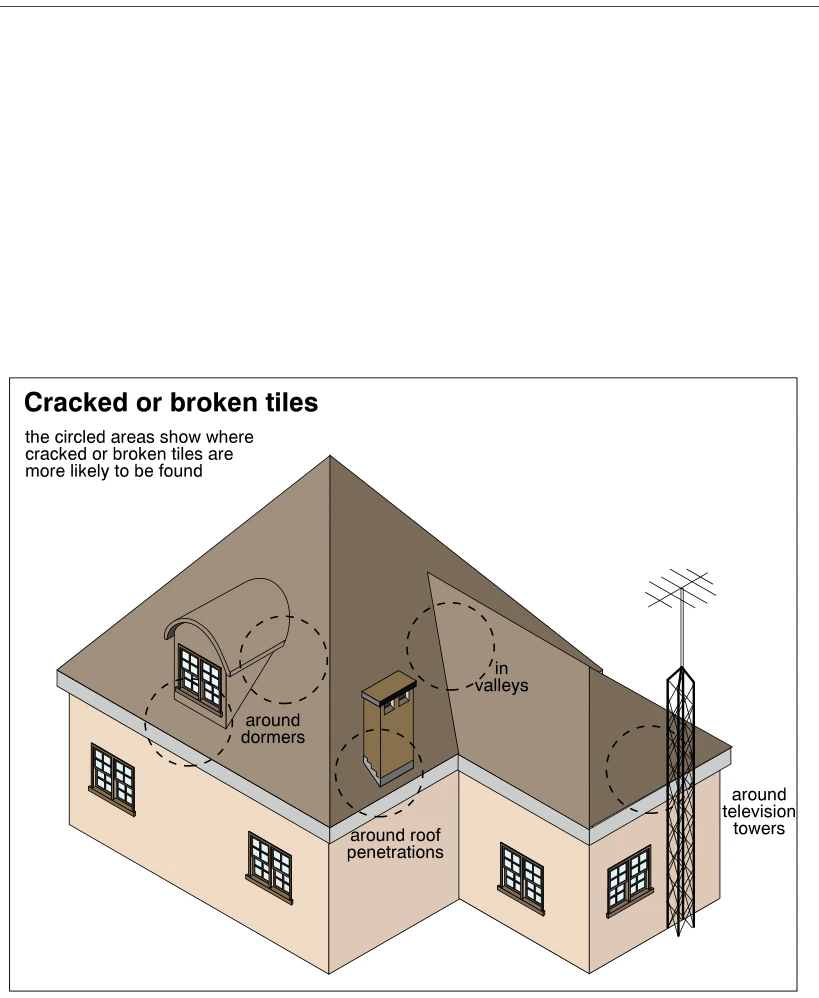
0046Cracked or broken tiles
· p. 16
The illustration shows a house with intersecting sloped roof planes, a dormer, a chimney-like roof penetration, and an exterior television antenna tower. Dashed circles identify locations where cracked or broken concrete roof tiles are more likely to be found. These locations include the roof around the dormer, a roof valley, the base of the roof penetration, and the roof adjacent to the television tower. Individual tiles and actual fractures are not drawn; the diagram identifies areas to examine for damage.
 0047
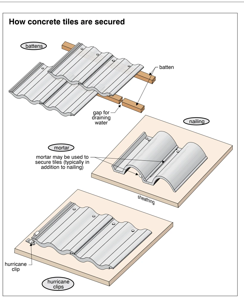
0047How concrete tiles are secured
· p. 16
The illustration shows several methods of securing profiled concrete roof tiles. The upper detail depicts overlapping tile courses supported on battens, with a gap between batten ends for draining water. The middle detail shows tiles on roof sheathing with nail attachment locations and mortar that may supplement nailing. The lower detail shows a hurricane clip engaging a tile edge and fastening to the sheathing. These are presented as securement options rather than examples of defects.
 0048
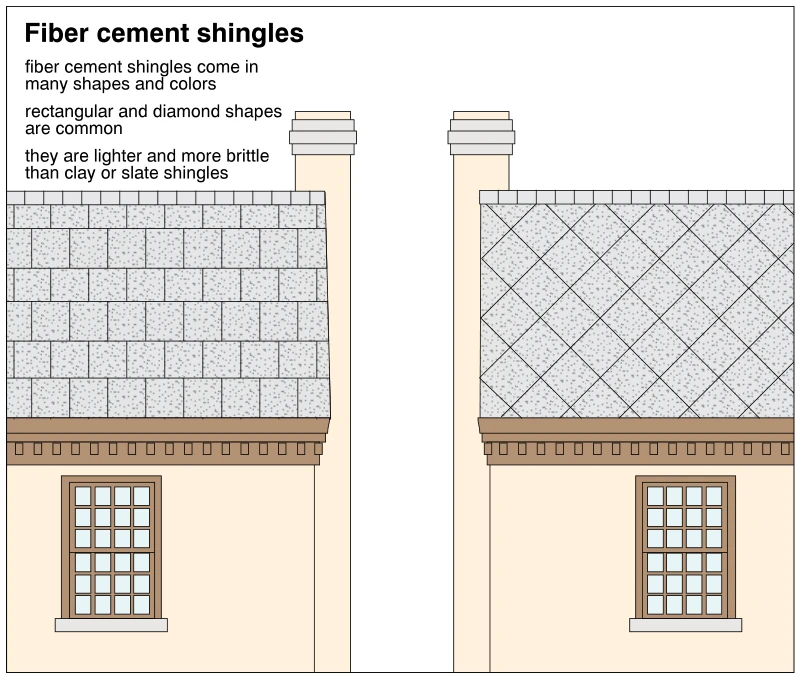
0048Fiber cement shingles
· p. 16
The illustration shows two roof elevations with fiber cement shingle coverings. The left roof has rectangular shingles laid in horizontal courses with staggered joints, while the right roof has a diamond-pattern shingle layout. Both roofs are shown above cornice trim and windows, with chimneys beside the roof slopes. The annotations identify common shingle shapes and state that fiber cement shingles are lighter and more brittle than clay or slate shingles. No damage or improper installation is depicted.
 0049
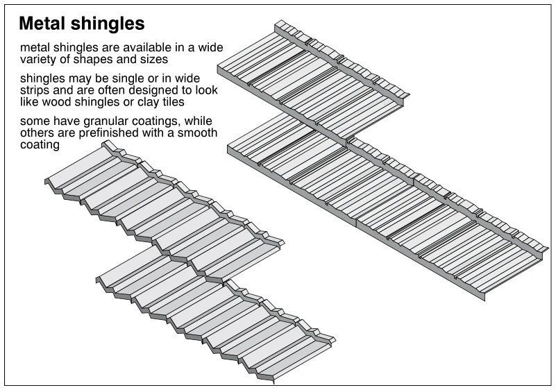
0049Metal shingles
· p. 16
The illustration shows two styles of formed metal roofing shingles in offset, overlapping strips. One style has closely spaced longitudinal ribs, while the other has broader raised profiles and a scalloped lower edge. Both styles have shaped upper edges and repeated profiles across each strip. The annotations explain that metal shingles come in various shapes and sizes, may resemble wood shingles or clay tiles, and may have granular or smooth prefinished coatings. No defects or installation failures are depicted.
Steep Roof Flashings ·Valley Flashingsp. 17
 0050
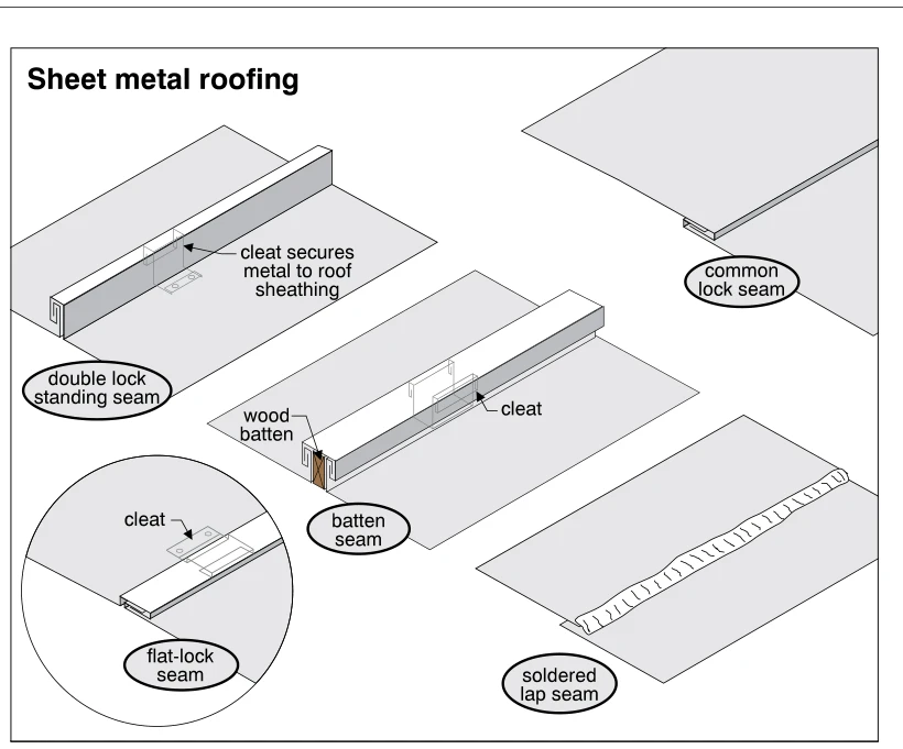
0050Sheet metal roofing
· p. 17
The illustration shows five methods of joining sheet metal roofing: double lock standing seam, batten seam, flat-lock seam, common lock seam, and soldered lap seam. The double lock standing seam has raised, folded panel edges and a cleat identified as securing the metal to the roof sheathing. The batten seam incorporates a wood batten between raised metal edges, with a metal cover and securing cleat. A circular detail shows the folded joint and cleat at a flat-lock seam, while separate views show a common lock seam and a soldered overlapping joint. No defects or improper installation conditions are indicated.
 0051
0051Roll roofing
· p. 17
The illustration shows overlapping courses of roll roofing installed across sloped roof sheathing. Curled-back edges reveal the smooth selvage portions beneath the mineral-surfaced exposed portions, with rows of fasteners along the concealed upper edges. The layers are cemented together, with a bead of cement below the bottom edge of each layer. The drawing identifies the downslope direction and specifies course exposure as L/2 minus 2 inches, typically 16 inches.
 0052
0052Roll roofing problems
· p. 17
The illustration shows a section of roll roofing with several common surface and seam defects. A localized patch is identified as loss of granular material, while long raised ridges indicate buckling or wrinkling. An overlapping seam is lifted open, and nearby bubbles indicate blistering. Two exposed fastener locations along the overlap are identified as fastener problems.
 0053
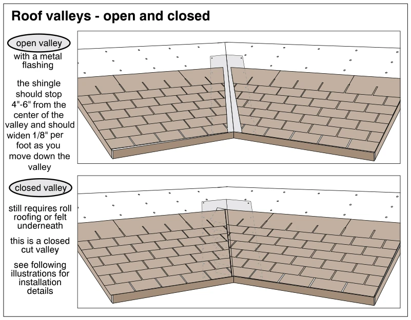
0053Roof valleys - open and closed
· p. 17
Two diagrams compare open and closed valleys at the intersection of sloping shingle roof planes. The upper diagram shows an open valley with exposed metal flashing between the shingle edges. Its annotation specifies that shingles should stop 4–6 inches from the valley center and that the opening should widen 1/8 inch per foot down the valley. The lower diagram shows a closed-cut valley, with shingles covering the valley lining and meeting along a cut line. The accompanying note states that roll roofing or felt is still required underneath.
 0054
0054Why valleys have a lower slope
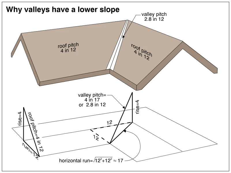
· p. 17
The upper drawing shows two intersecting roof planes, each with a pitch of 4 in 12, meeting at a valley marked with a narrow white strip. The valley has a lower pitch of 2.8 in 12. The lower geometric diagram compares the roof-plane slope with the diagonal valley slope using the same rise of 4 units. Two perpendicular horizontal runs of 12 units produce a diagonal horizontal run of approximately 17 units, giving the valley a pitch of 4 in 17, or approximately 2.8 in 12.
 0055
0055Valley flashing
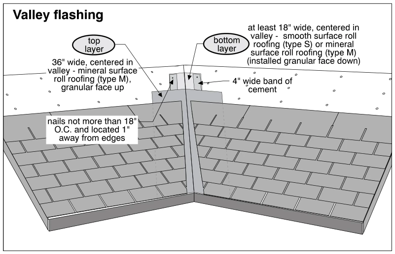
· p. 17
The illustration shows two shingled roof slopes meeting at an open valley lined with two layers of roll roofing. The bottom layer is at least 18 inches wide and centered in the valley, using either smooth-surface type S roofing or mineral-surface type M roofing installed granular face down. The top layer is 36 inches wide, centered in the valley, and consists of mineral-surface type M roll roofing with the granular face up. Cutaway portions expose the layered assembly and a specified 4-inch-wide band of cement. The fastening annotation specifies nails no more than 18 inches on center and 1 inch from the edges.
 0056
0056Valley flashing made of asphalt shingles
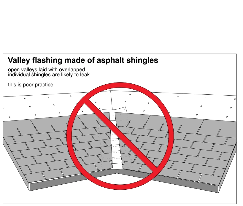
· p. 18
Two asphalt-shingled roof slopes meet at an open valley. Overlapping individual shingles form the valley lining, with the adjacent roof shingles cut back to expose the drainage channel. A large red prohibition symbol marks this installation as improper. The annotations warn that open valleys lined with overlapped individual shingles are likely to leak.
 0057
0057Metal valley flashing
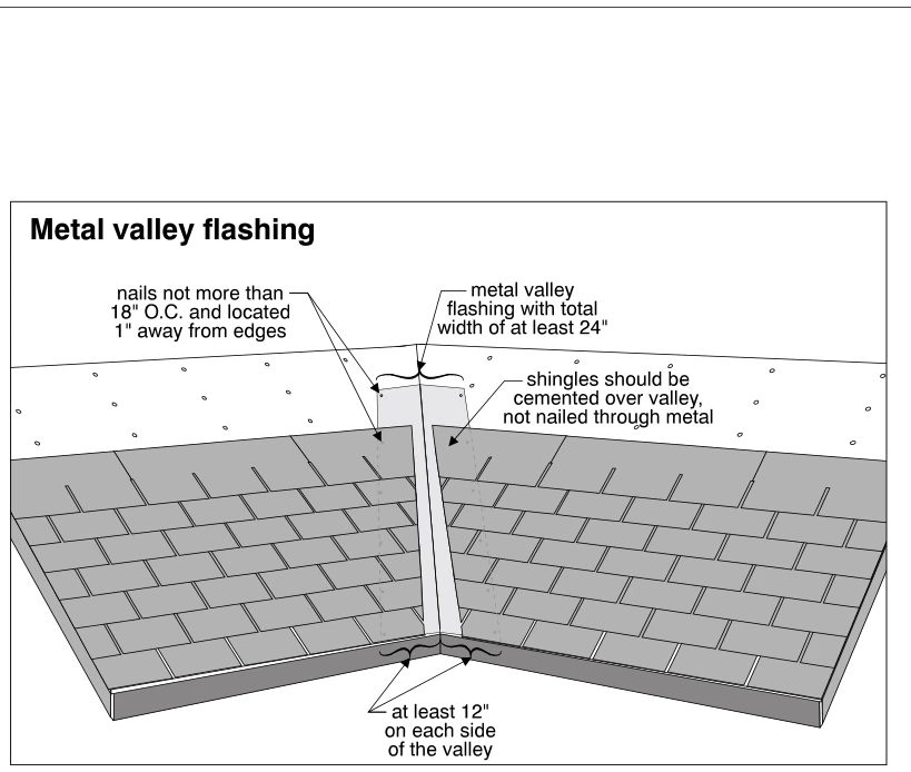
· p. 18
The illustration shows two shingled roof slopes meeting at an open valley lined with metal flashing. The flashing extends beneath the shingles on both sides, with a total width of at least 24 inches and at least 12 inches on each side of the valley. Flashing nails are specified at no more than 18 inches on center and 1 inch from the edges. Shingles overlapping the valley flashing are to be cemented in place rather than nailed through the metal.
 0058
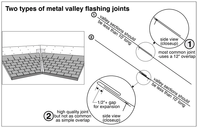
0058Two types of metal valley flashing joints
· p. 18
The illustration shows metal valley flashing between two adjoining shingled roof slopes and compares two joints used to connect flashing sections. The first joint is a simple lap with a 12-inch overlap, identified as the most common joint. The second uses interlocking folded ends with a gap of at least 1/2 inch for expansion and is identified as a higher-quality but less common joint. Enlarged side views show the geometry of both connections. Both details specify that valley flashing sections should be less than 10 feet long.
 0059
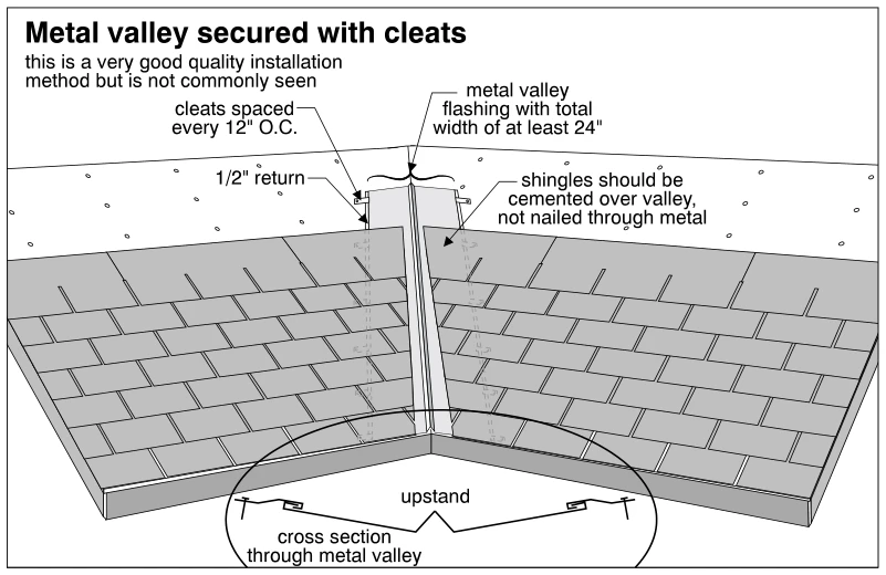
0059Metal valley secured with cleats
· p. 18
The illustration shows an open metal valley between two shingled roof slopes, with flashing secured along its edges by cleats spaced every 12 inches on center. The flashing is labeled as having a total width of at least 24 inches and a 1/2-inch return at its edges. Shingles overlap the outer portions of the flashing and are to be cemented in place rather than nailed through the metal. An enlarged cross section shows the central upstand and the cleats engaging the returned flashing edges. The drawing identifies this as a very good quality installation method that is not commonly seen.
 0060
0060Metal valley flashing - alternate application
· p. 18
The illustration shows an open metal valley between two intersecting shingle-covered roof slopes. Metal flashing is centered in the valley, with a total width of at least 24 inches and at least 12 inches on each side. Nails are specified at no more than 18 inches on center and 1 inch from the flashing edges. Ice and water shield extends beneath the metal edges to improve nail-hole watertightness, extend flashing coverage by 18 inches on each side, and provide additional adhesion to the roof.
 0061
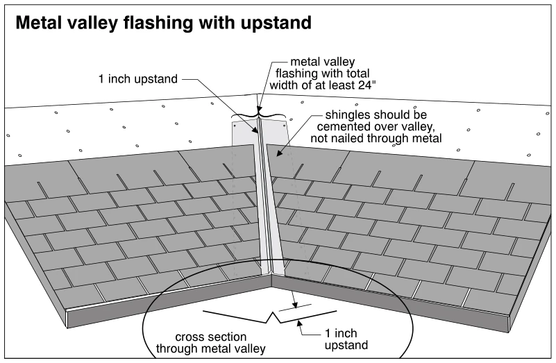
0061Metal valley flashing with upstand
· p. 18
Two shingled roof slopes intersect at an open valley lined with metal flashing. The flashing has a central 1-inch upstand, illustrated both along the valley and in an enlarged cross section below. An annotation specifies a total flashing width of at least 24 inches. Shingles overlap the outer edges of the flashing, and the drawing directs that they be cemented in place rather than nailed through the metal.
Steep Roof Flashings ·Chimney Flashingsp. 19
 0062
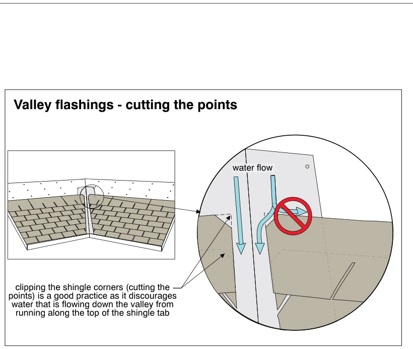
0062Valley flashings - cutting the points
· p. 19
The illustration shows a shingled roof valley with exposed metal valley flashing between two roof slopes. An enlarged detail shows the upper corners of shingles bordering the valley clipped back, with dashed lines indicating the original points. Blue arrows show water flowing down the flashing, and a prohibition symbol marks the unwanted sideways flow along the top of a shingle tab. Clipping these corners is identified as good practice to discourage valley runoff from being diverted beneath the shingles.
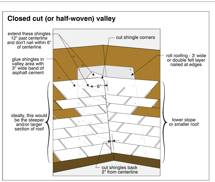 0063
0063Closed cut (or half-woven) valley
· p. 19
The illustration shows a closed-cut, or half-woven, shingle valley at the intersection of two roof slopes. Shingles from the ideally steeper or larger roof section extend 12 inches past the valley centerline, with no nails within 6 inches of the centerline. Shingles on the lower-slope or smaller roof section overlap them and are cut back 2 inches from the centerline, with their corners clipped. A 3-inch-wide band of asphalt cement bonds shingles in the valley area. Beneath the shingles, the valley lining consists of 3-foot-wide roll roofing or a double felt layer nailed at the edges.
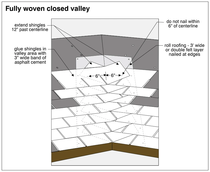 0064
0064Fully woven closed valley
· p. 19
The illustration shows two shingled roof slopes meeting at a fully woven closed valley. Shingle courses from opposing slopes interlace across the valley, with shingles extending 12 inches past the centerline. Beneath the woven shingles, the valley lining consists of 3-foot-wide roll roofing or a double layer of felt nailed at its edges. The drawing specifies a 3-inch-wide band of asphalt cement to bond shingles in the valley area and prohibits nailing within 6 inches of either side of the valley centerline.
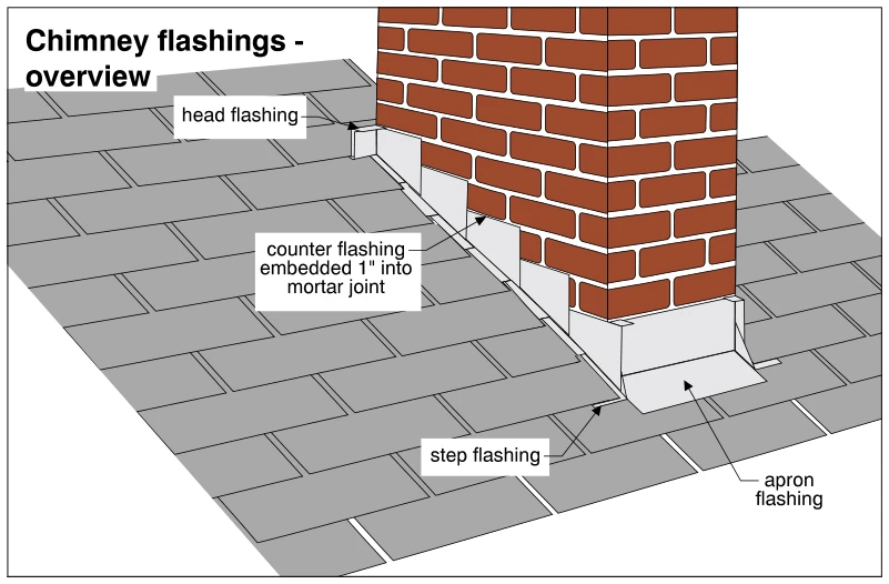 0065
0065Chimney flashings - overview
· p. 19
The illustration shows a brick chimney penetrating a sloped, shingled roof, with flashing arranged around its base. Head flashing is located at the uphill side, while step flashing follows the roof slope along the chimney side and interleaves with the shingles. Counter flashing covers the vertical legs of the base flashing and is labeled as embedded 1 inch into a mortar joint. Apron flashing at the downhill face extends outward over the roof covering to shed water. No flashing defects are depicted.
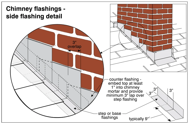 0066
0066Chimney flashings - side flashing detail
· p. 19
The illustration shows side flashing at the junction of a brick chimney and a shingled roof, with an enlarged detail and a separate step-flashing diagram. Individual step or base flashings are interwoven with the shingle courses and turn up against the chimney. Counter flashing is embedded at least 1 inch into the chimney mortar and laps over the step flashing by a minimum of 3 inches. Adjacent counter-flashing sections have a labeled 3-inch overlap. The separate diagram shows overlapping bent flashing pieces with 3-inch dimensions and a typical length of approximately 9 inches.
 0067
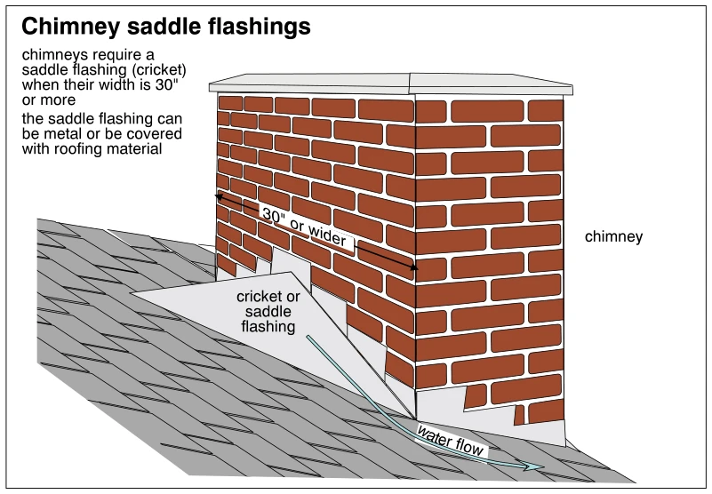
0067Chimney saddle flashings
· p. 19
A brick chimney projects through a sloped shingle roof, with a raised cricket or saddle flashing at its upslope face. The saddle forms sloping surfaces that divert runoff around the chimney, as indicated by the water-flow arrow. Flashing extends up the masonry at the roof intersection. A dimension identifies the chimney as 30 inches or wider, and the annotations state that chimneys of this width require a saddle flashing. The saddle may be metal or covered with roofing material.
Steep Roof Flashings ·Roof/Wall Flashingsp. 20
 0068
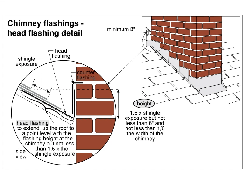
0068Chimney flashings - head flashing detail
· p. 20
The illustration shows a brick chimney passing through a shingled roof, with metal flashing around its base and an enlarged side view of the uphill head flashing. The head flashing extends beneath the uphill shingles and turns up against the chimney, where counter flashing covers its vertical leg. The specified flashing height is 1.5 times the shingle exposure, but not less than 6 inches or one-sixth the chimney width. The roof leg must extend uphill to a point level with the flashing height at the chimney, and at least 1.5 times the shingle exposure. A minimum 3-inch dimension is also marked at the counter-flashing overlap.
 0069
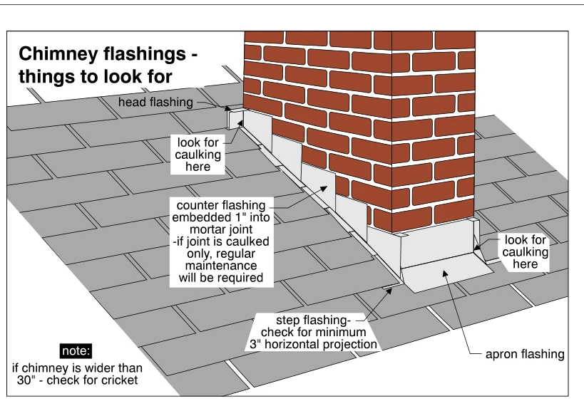
0069Chimney flashings - things to look for
· p. 20
The illustration shows a brick chimney penetrating a sloped shingle roof, with head flashing on the uphill side, step flashing along the side, and apron flashing on the downhill face. Counter flashing overlaps the roof flashing and is identified as embedded 1 inch into a mortar joint. An annotation warns that a joint sealed only with caulking will require regular maintenance, and arrows identify corner locations to check for caulking. The step flashing annotation calls for a minimum 3-inch horizontal projection. A note directs the inspector to check for a cricket if the chimney is wider than 30 inches.
 0070
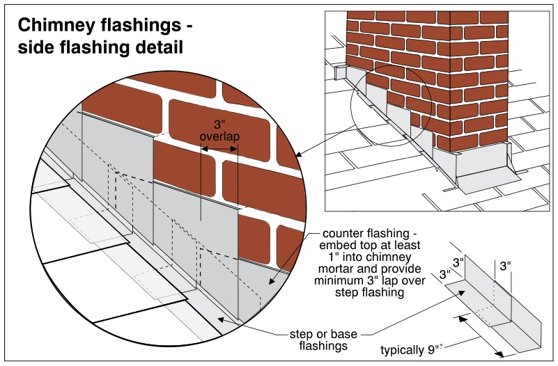
0070Chimney flashings - side flashing detail
· p. 20
The illustration shows side flashing at a brick chimney where it intersects a shingle roof, with a magnified detail and a separate flashing-piece diagram. Individual step or base flashings are interwoven with the shingle courses and turn up against the chimney. Counter flashing embedded in the chimney mortar covers the vertical legs of the step flashing. The annotations specify at least 1 inch of embedment into mortar, a minimum 3-inch lap over the step flashing, and a 3-inch overlap between adjacent counter-flashing sections. The separate diagram indicates 3-inch flashing legs, a 3-inch overlap, and a typical length of approximately 9 inches.
 0071
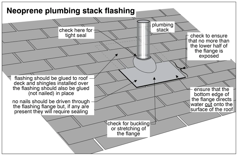
0071Neoprene plumbing stack flashing
· p. 20
The illustration shows a plumbing vent stack penetrating a shingled roof through a neoprene flashing boot and flange. The boot seals tightly around the pipe, while the upper portion of the flange lies beneath the shingles and the lower portion discharges water onto the roof surface. Annotations specify that no more than the lower half of the flange should be exposed and that the flashing and overlapping shingles should be glued rather than nailed in place. Inspection callouts emphasize checking the pipe seal, flange buckling or stretching, and sealing any nails that penetrate the flange.
 0072
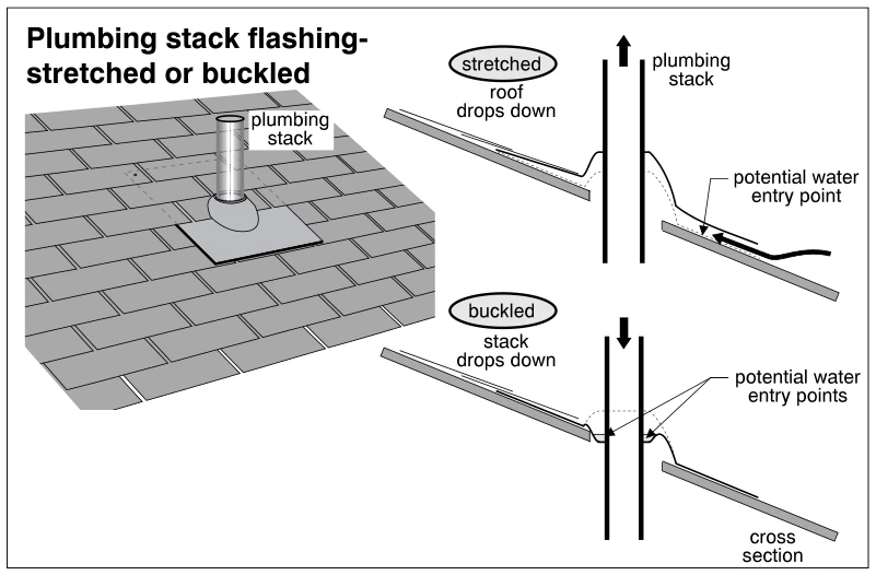
0072Plumbing stack flashing- stretched or buckled
· p. 20
The illustration shows a plumbing stack penetrating a shingle roof, with a flashing collar and base surrounding the pipe. Two cross sections illustrate flashing deformation caused by relative movement between the roof and stack. In the upper section, the roof drops down relative to the stack, stretching the flashing and creating a potential water entry point at its roof interface. In the lower section, the stack drops down relative to the roof, buckling the flashing and creating potential water entry points around the stack.
 0073
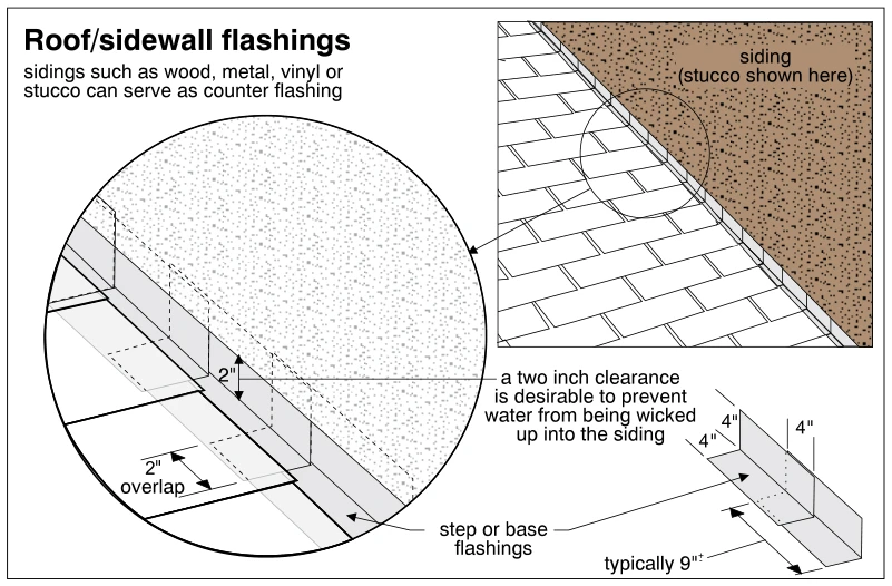
0073Roof/sidewall flashings
· p. 20
The illustration shows a shingled sloping roof meeting a stucco-clad sidewall, with an enlarged detail of the step flashing at the junction. Individual flashing pieces are interwoven with the shingle courses and overlap by 2 inches. Their vertical legs extend behind the wall siding, which serves as counter flashing. A 2-inch clearance between the siding and roof surface is identified as desirable to prevent water from wicking into the siding. A separate detail shows bent flashing pieces with 4-inch dimensions and a typical length of approximately 9 inches.
Steep Roof Flashings ·Hip and Ridge Flashingsp. 21
 0074
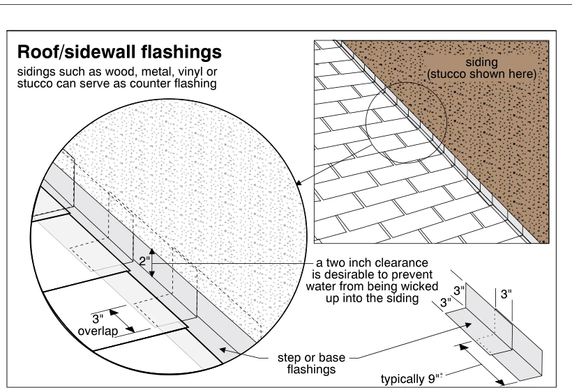
0074Roof/sidewall flashings
· p. 21
The illustration shows a shingled roof meeting a stucco-clad sidewall, with an enlarged detail of the step flashing installation. Individual bent flashing pieces interleave with the shingle courses and extend up the wall behind the siding, which serves as counter flashing. The detail specifies a 3-inch flashing overlap and a desirable 2-inch clearance between the siding and roof to prevent water from wicking into the siding. A separate flashing diagram shows the bent profile with 3-inch dimensions and a typical 9-inch length.
 0075
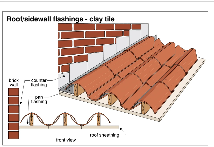
0075Roof/sidewall flashings - clay tile
· p. 21
The illustration shows a clay tile roof meeting a brick sidewall, with a perspective view and a front-view section. Pan flashing runs along the wall beneath the edge of the adjacent tile, forming a drainage channel at the roof-to-wall junction. Stepped counter flashing on the brick wall overlaps the upturned wall leg of the pan flashing. The section shows the curved tile profile, wood supports, and roof sheathing beneath the tile assembly. No flashing defects are depicted.
 0076
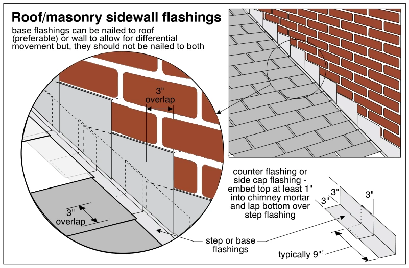
0076Roof/masonry sidewall flashings
· p. 21
The illustration shows a shingled sloping roof meeting a brick masonry sidewall, with an enlarged detail of the flashing assembly. Individual step or base flashings interleave with the shingles and turn up against the wall, while counter flashing embedded in mortar joints laps over their vertical legs. The enlarged detail indicates 3-inch overlaps, and a separate folded-flashing diagram shows 3-inch dimensions and a typical length of approximately 9 inches. An annotation specifies embedding the counter flashing at least 1 inch into the mortar. The fastening note permits attachment of base flashing to the roof, preferably, or to the wall, but not both, to allow differential movement.
 0077
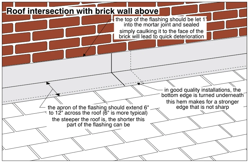
0077Roof intersection with brick wall above
· p. 21
The illustration shows apron flashing at the intersection of a shingled roof and a brick wall extending above it. The flashing rises against the wall and extends outward over the roof covering. An annotation specifies that the top should be let 1 inch into a mortar joint and sealed, warning that merely caulking it to the brick face leads to quick deterioration. The roof apron is specified to extend 6 to 12 inches across the roof, with 6 inches more typical and a shorter apron possible on steeper roofs. The lower edge is shown turned underneath to form a strengthening hem that eliminates a sharp exposed edge.
 0078
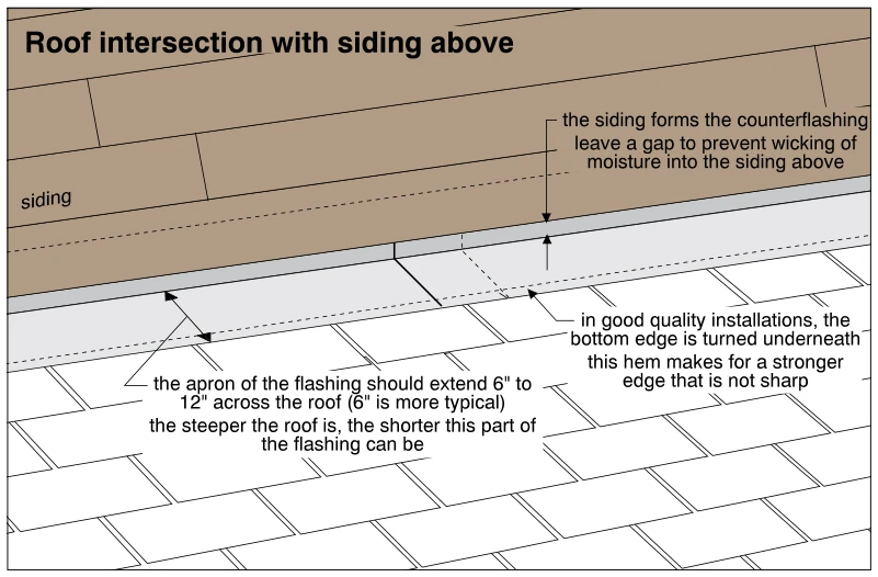
0078Roof intersection with siding above
· p. 21
The illustration shows apron flashing at the intersection of a shingled roof and a wall with horizontal siding above. The siding overlaps the flashing's vertical leg and acts as counterflashing, with a clearance gap to prevent moisture wicking into the siding. The flashing apron extends over the roof shingles; the annotation specifies 6 to 12 inches, with 6 inches more typical and a shorter apron possible on steeper roofs. A turned-under hem at the lower edge of the flashing is identified as a good-quality detail that strengthens the edge and eliminates a sharp exposed edge.
 0079
0079Ridge shingle application
· p. 21
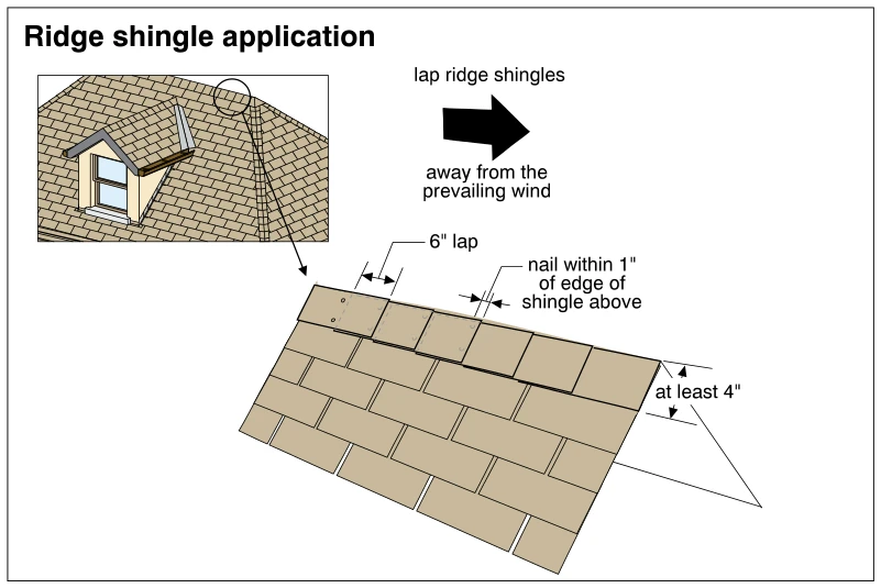
The illustration shows overlapping ridge cap shingles covering the junction of two shingled roof slopes. An inset locates the ridge detail on a roof with a dormer and a hip. The enlarged detail specifies a 6-inch lap and directs that ridge shingles be lapped away from the prevailing wind. Nails are to be placed within 1 inch of the edge of the shingle above, and the cap extends at least 4 inches down the roof slope from the ridge.
Steep Roof Flashings ·Drip Edge Flashingsp. 22
 0080
0080Skylight in sloped roof - curb mount
· p. 22
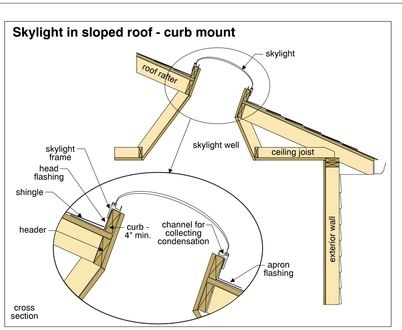
The illustration shows a cross section of a curb-mounted skylight in a sloped shingle roof, with a skylight well extending down to the ceiling opening. Roof rafters, a header, ceiling joists, and an exterior wall establish the surrounding framing. An enlarged detail shows the skylight frame supported on a raised curb labeled as a minimum of 4 inches. Head flashing connects the uphill side of the curb to the roof covering, while apron flashing extends over the shingles on the downhill side. A channel within the skylight frame is identified for collecting condensation.
 0081
0081Skylight in sloped roof - curbless
· p. 22
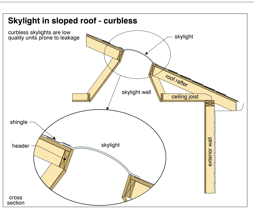
The illustration shows a cross section of a curbless skylight installed in a sloped shingle roof above a skylight well. Roof rafters, headers, ceiling joists, and an exterior wall provide the surrounding framing context. An enlarged detail shows the curved skylight spanning the roof opening, with its edges meeting the roof covering directly rather than sitting on a raised curb. The annotation identifies curbless skylights as low-quality units prone to leakage.
 0082
0082Skylight in sloped roof - integral curb (self-flashing skylight)
· p. 22
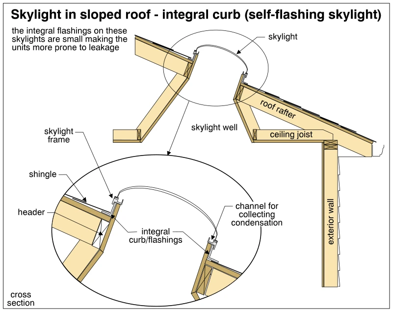
A cross section shows a domed, self-flashing skylight installed in a sloped shingle roof, with a skylight well extending down to the ceiling. The surrounding structure includes roof rafters, a header, ceiling joists, and an exterior wall. An enlarged detail shows the skylight frame, integral curb and flashings, and a channel for collecting condensation. The annotation warns that the small integral flashings make these skylights more prone to leakage; no active leak is depicted.
 0083
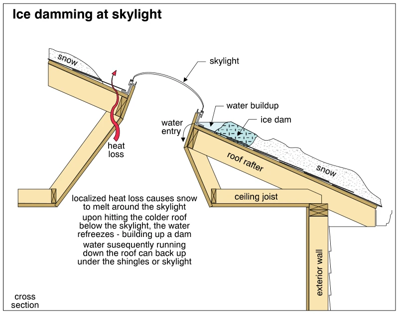
0083Ice damming at skylight
· p. 22
A cross section shows a domed skylight installed in a snow-covered sloping roof supported by rafters, ceiling joists, and an exterior wall. An upward arrow indicates localized heat loss beside the skylight, melting nearby snow. Meltwater refreezes on the colder roof downslope of the skylight, forming an ice dam that holds water against its lower edge. A water-entry arrow shows backed-up water entering at the skylight-to-roof junction, and the annotation explains that water can back up under the shingles or skylight.
 0084
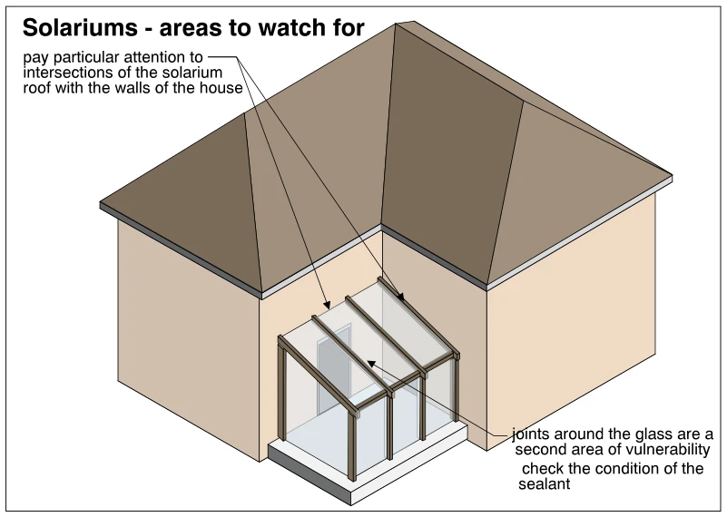
0084Solariums - areas to watch for
· p. 22
The illustration shows a glazed solarium attached at an inside corner of a house beneath the main roof. Sloped glass roof panels and vertical glass walls are supported by framing on a raised base. Arrows identify the intersections of the solarium roof with the house walls as areas requiring particular attention. Additional annotations identify joints around the glass as vulnerable areas and direct the inspector to check the sealant condition. No specific damage or failed joint is depicted.
 0085
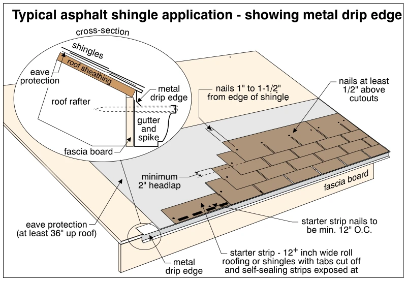
0085Typical asphalt shingle application - showing metal drip edge
· p. 22
The illustration shows a cutaway asphalt-shingle roof installation at an eave, with staggered shingle courses over eave protection and a starter strip. Callouts specify minimum headlap, nail positions relative to shingle edges and cutouts, and starter-strip nail spacing. Metal drip edge runs along the roof perimeter above the fascia, with eave protection extending at least 36 inches up the roof. An enlarged cross-section shows the relationship of shingles, roof sheathing, eave protection, drip edge, fascia board, roof rafter, and a gutter secured with a spike.
Flat Roofing ·Built-Up Roofing (Tar and Gravel)p. 23
 0086
0086Dormer siding flashings
· p. 23
The illustration shows a gable-roof dormer with a window projecting from a shingled main roof. Step flashings follow the sloping junction between the dormer sidewall and the main roof, interwoven with the shingle courses. The siding is held above the roof shingles, with an annotation specifying 2 inches of clearance to prevent water damage. An exposed metal valley flashing is also visible where the dormer roof meets the main roof.
 0087
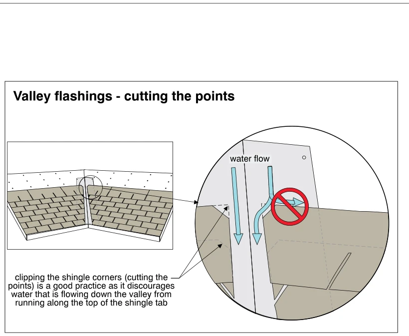
0087Valley flashings - cutting the points
· p. 23
The illustration shows two shingled roof planes meeting at an open valley with exposed valley flashing. A circular enlargement details the shingle edges and clipped corners alongside the flashing. Blue arrows indicate water flowing down the valley, while a prohibition symbol marks unwanted sideways flow along the top of a shingle tab. Clipping the shingle corners, described as cutting the points, is presented as good practice to discourage this lateral water movement.
 0088
0088Flat roof drainage systems
· p. 23
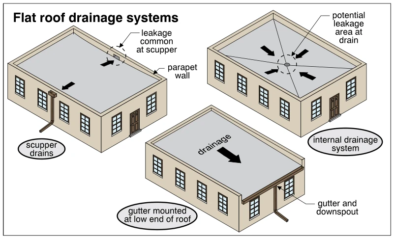
The illustration shows three drainage arrangements for flat or low-slope roofs. One roof drains through scuppers in parapet walls, with an exterior downspout shown at one outlet and a note identifying leakage as common at scuppers. A second roof directs water inward toward a central roof drain, identified as a potential leakage area. The third roof slopes toward an open low edge equipped with a gutter and exterior downspout. Arrows indicate the direction of roof drainage in each arrangement.
 0089
0089Inverted Roof Membrane Assembly (IRMA)
· p. 23
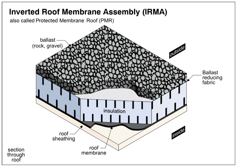
The illustration shows a cutaway section of an inverted roof membrane assembly, also called a protected membrane roof. The roof membrane lies directly above the roof sheathing and below the insulation. Ballast reducing fabric separates the insulation from the rock or gravel ballast at the exterior surface. The cutaway exposes the layer sequence from the interior side to the exterior; no defects are depicted.
 0090
0090Built up roofing membrane - 4 ply
· p. 23
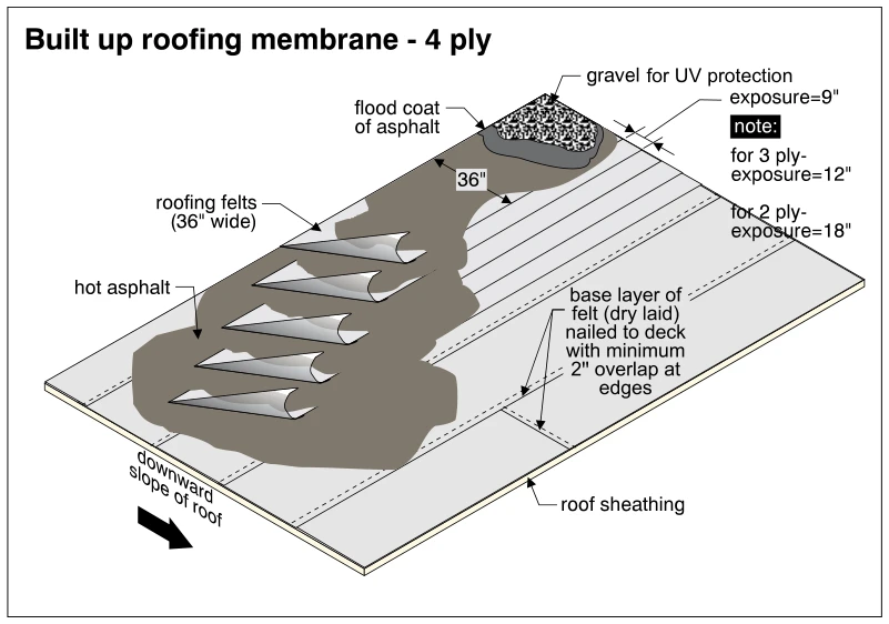
The illustration shows a cutaway of a four-ply built-up roofing membrane over roof sheathing. A dry-laid felt base layer is nailed to the deck with a minimum 2-inch overlap at its edges. Above this base, 36-inch-wide roofing felts overlap with a 9-inch exposure and are embedded in hot asphalt; curled-back ends reveal the successive layers. A flood coat of asphalt and gravel surfacing provide the top finish, with the gravel identified as UV protection. Notes specify 12-inch exposure for three-ply roofing and 18-inch exposure for two-ply roofing, and an arrow indicates the downward roof slope.
 0091
0091Damaged and patched flat roofs
· p. 23
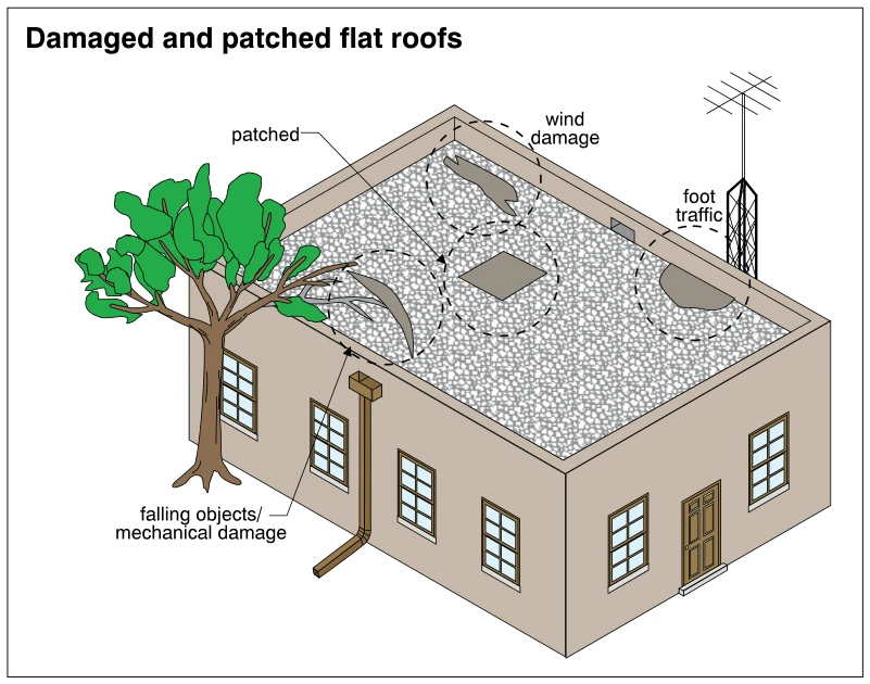
The illustration shows a gravel-surfaced built-up flat roof enclosed by perimeter parapet walls. Dashed outlines highlight a rectangular roof patch and three damaged areas. Wind damage is depicted as a lifted or torn section near the rear roof corner, while foot traffic is associated with an exposed area near a rooftop antenna. An overhanging tree extends across another torn section labeled as falling-object or mechanical damage. A drainage outlet and exterior downspout are also shown.
Flat Roofing ·Modified Bitumenp. 24
 0092
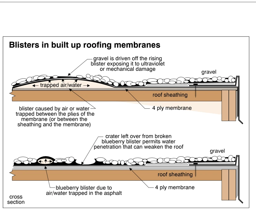
0092Blisters in built up roofing membranes
· p. 24
Two cross sections depict blister defects in gravel-surfaced, four-ply built-up roofing over roof sheathing. The upper section shows a broad membrane blister caused by air or water trapped between membrane plies or between the membrane and sheathing. Gravel is displaced from the raised blister, leaving the membrane exposed to ultraviolet or mechanical damage. The lower section shows a smaller blueberry blister caused by air or water trapped in the asphalt, alongside a crater left by a broken blister. The crater permits water penetration that can weaken the roof.
 0093
0093Flat roof alligatoring
· p. 24
The illustration shows a flat-roofed building with parapet walls surrounding an exposed roofing surface. A circular detail linked to the roof enlarges a network of irregular, interconnected cracks in the exposed asphalt. This scale-like cracking pattern is identified as alligatoring, a deterioration condition to watch for during inspection. An exterior downspout and a small opening in a parapet wall are also shown.
 0094
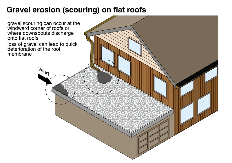
0094Gravel erosion (scouring) on flat roofs
· p. 24
The illustration shows a gravel-covered flat garage roof adjoining a taller house with a pitched roof. Bare patches expose the roof membrane at a windward corner and beneath a downspout that discharges directly onto the flat roof. A wind arrow and dashed circles identify the areas subject to gravel scouring. The annotations explain that loss of protective gravel can lead to rapid deterioration of the roof membrane.
 0095
0095Ridging and fishmouths on flat roofs
· p. 24
The illustration shows a roofing felt ply on a flat roof with two elongated raised ridges or wrinkles in its surface. The annotation identifies lack of asphalt, moisture, felt slippage, or differential thermal expansion as possible causes. A separate raised fold extends to the edge of the felt ply, forming an open fishmouth. This edge opening potentially allows water direct access beneath the ply.
 0096
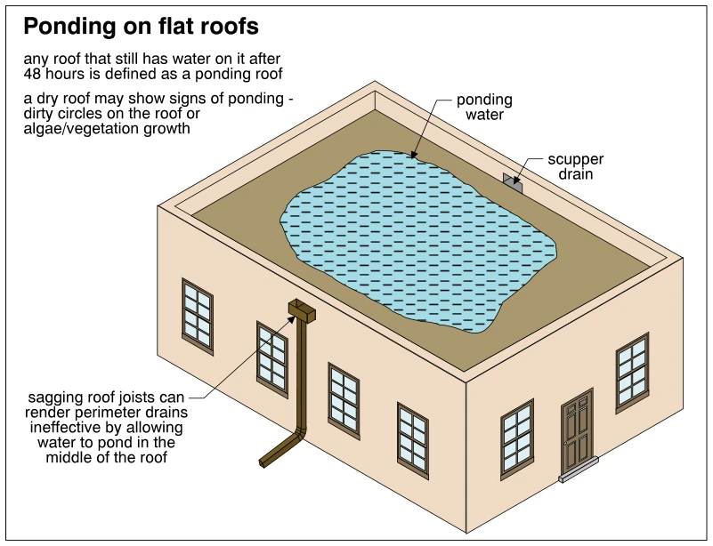
0096Ponding on flat roofs
· p. 24
An oblique view of a building shows a flat roof enclosed by parapet walls, with a large pool of standing water in the middle. A scupper drain is visible through a parapet, and an exterior collector and downspout are shown on another wall. The annotations explain that sagging roof joists can allow water to collect centrally rather than reach perimeter drains. The illustration defines ponding as water remaining after 48 hours and notes that dirty circles or algae/vegetation growth can indicate ponding on a dry roof.
 0097
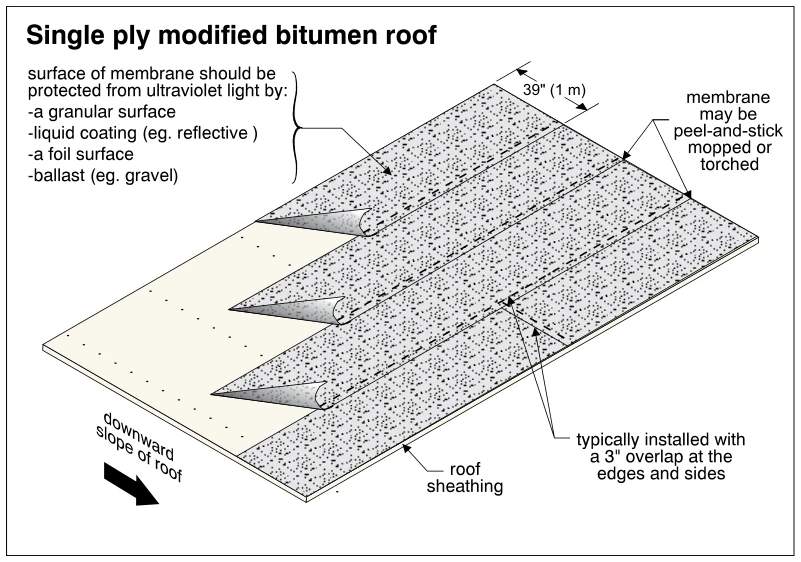
0097Single ply modified bitumen roof
· p. 24
The illustration shows parallel strips of single-ply modified bitumen roofing laid over roof sheathing, with several ends curled back to expose the underlying assembly. The membrane strips are marked as 39 inches (1 m) wide and typically installed with 3-inch overlaps at the edges and sides. An arrow identifies the downward slope of the roof. Annotations identify peel-and-stick, mopped, or torched installation methods and specify ultraviolet protection using a granular surface, liquid coating, foil surface, or ballast. No defects are depicted.
Flat Roofing ·Roll Roofingp. 25
 0098
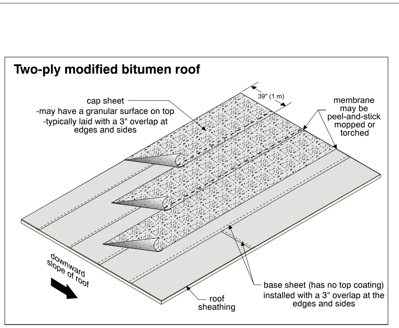
0098Two-ply modified bitumen roof
· p. 25
The illustration shows a two-ply modified bitumen roof assembly over roof sheathing. Partially rolled-back cap sheets expose the underlying base sheet and its overlapping seams. The cap sheet is shown with a granular surface, while the base sheet has no top coating; annotations specify 3-inch overlaps at edges and sides for both layers. A dimension identifies a 39-inch (1 m) membrane width, and another annotation lists peel-and-stick, mopped, or torched application methods. An arrow indicates the downward slope of the roof.
 0099
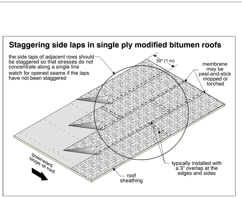
0099Staggering side laps in single ply modified bitumen roofs
· p. 25
The illustration shows overlapping strips of single-ply modified bitumen roofing over roof sheathing, with several edges lifted to reveal the layers. A circled area highlights staggered lap joints in adjacent rows, which distribute stresses rather than concentrating them along one line. Annotations identify a 39-inch (1 m) membrane width and a typical 3-inch overlap at edges and sides. The membrane may be peel-and-stick, mopped, or torched, and an arrow indicates the downward roof slope. A warning advises checking for opened seams where laps have not been staggered.
 0100
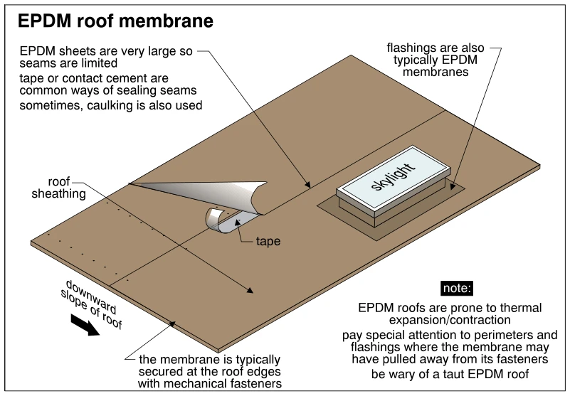
0100EPDM roof membrane
· p. 25
The illustration shows large EPDM roofing sheets installed over roof sheathing, with a peeled-back portion exposing a taped seam. A skylight sits on a raised curb surrounded by membrane flashing. Arrows identify the roof's downward slope and the perimeter where the membrane is typically mechanically fastened. Annotations explain seam-sealing methods and warn that thermal expansion and contraction can cause the membrane to pull away from fasteners at perimeters and flashings. A taut membrane is identified as a condition requiring caution, rather than illustrated as a definite failure.
 0101
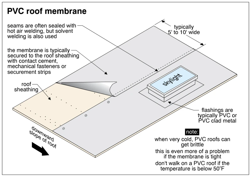
0101PVC roof membrane
· p. 25
The illustration shows PVC roofing membrane laid over roof sheathing, with one corner peeled back to expose the substrate. Adjacent membrane sheets form a seam, and annotations describe hot-air or solvent welding and attachment using contact cement, mechanical fasteners, or securement strips. A raised skylight has flashing around its base, identified as typically PVC or PVC-clad metal. Dimension arrows indicate membrane widths of typically 5 to 10 feet, and an arrow identifies the downward roof slope. A caution notes that PVC roofs can become brittle in cold weather, especially when the membrane is tight, and advises against walking on them below 50°F.
 0102
0102PVC roof problems
· p. 25
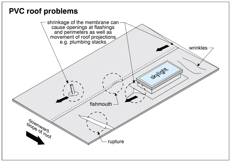
The illustration shows a sloped PVC membrane roof with a plumbing stack, a curb-mounted skylight, and a membrane seam. Arrows indicate membrane shrinkage, which the annotation identifies as a cause of openings at flashings and roof perimeters and movement of roof projections. Highlighted problem areas include the plumbing stack penetration, skylight flashing, and a fishmouth opening along the seam. Wrinkles appear near the upper-right roof edge, and a membrane rupture is shown near the lower edge. A large arrow identifies the downward slope of the roof.
 0103
0103Wide selvage roofing
· p. 25
The illustration shows overlapping courses of wide selvage roll roofing installed over roof sheathing, with the downward roof slope indicated. Each strip has a smooth selvage portion and a mineral-surfaced portion, with fasteners shown along the upper edge of the selvage. Curled-back ends reveal the overlapping layers and the cement bonding between them. An annotation specifies a bead of cement below the bottom edge of each layer. The indicated exposure is L/2 minus 2 inches, typically 16 inches.
Flat Roofing ·Flat Roof Flashingsp. 26
 0104
0104Built-up flat roof/wall flashing
· p. 26
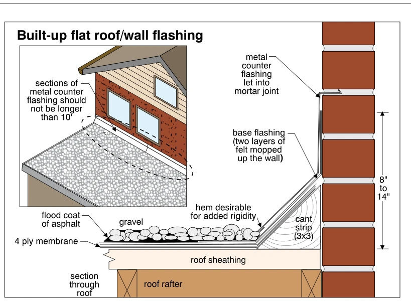
The illustration shows a gravel-surfaced built-up flat roof meeting a masonry wall, with an overview inset and an enlarged section through the flashing assembly. A four-ply membrane lies over roof sheathing supported by roof rafters, beneath an asphalt flood coat and gravel. A triangular cant strip supports the transition from the horizontal roof to the wall, where two layers of felt form the base flashing. Metal counter flashing is let into a mortar joint and overlaps the base flashing, with a hem identified as desirable for rigidity. The drawing indicates a flashing height of 8 to 14 inches above the sheathing level and specifies that metal counter flashing sections should not exceed 10 feet in length.
 0105
0105Modified bitumen roof/wall flashing
· p. 26
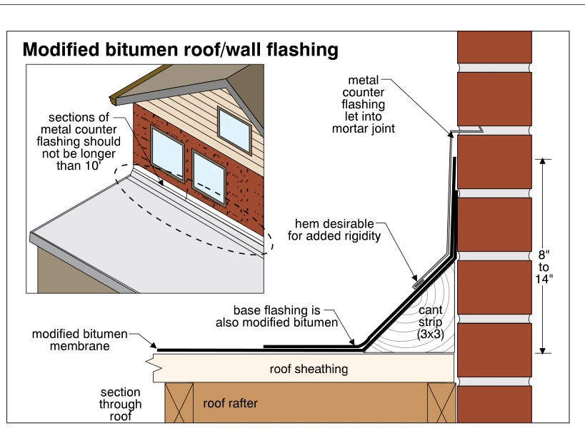
The illustration shows a modified bitumen roof-to-masonry-wall flashing assembly in section, with an inset locating the flashing along a building wall. Modified bitumen base flashing overlaps the roof membrane and turns up the wall over a 3-by-3 cant strip. Metal counter flashing is let into a mortar joint and extends down over the base flashing, with a hem recommended for added rigidity. A vertical dimension of 8 to 14 inches is indicated from the roof surface to the upper portion of the base flashing. The inset specifies that sections of metal counter flashing should not exceed 10 feet in length.
 0106
0106Two-piece counter flashing
· p. 26
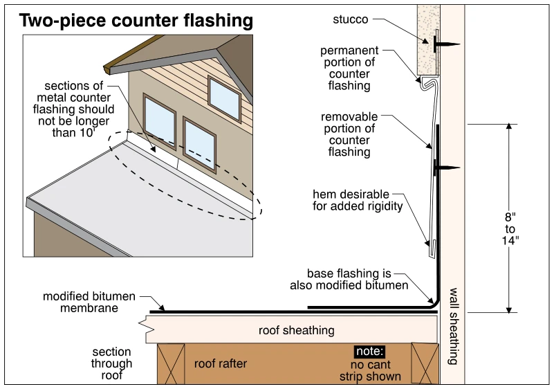
The illustration shows a two-piece metal counter flashing assembly at a low-slope roof-to-stucco-wall intersection, with an inset showing its location along a house wall. In section, the modified bitumen roof membrane turns up the wall as base flashing, overlapped by a removable counter flashing portion. The removable portion engages a permanent portion set beneath the stucco, and a hem at its lower edge is recommended for rigidity. A vertical dimension indicates 8 to 14 inches from the roof membrane level to the top of the base flashing. The inset specifies that metal counter flashing sections should not exceed 10 feet in length, and a note states that no cant strip is shown.
 0107
0107Built up roofing membrane - edge details
· p. 26
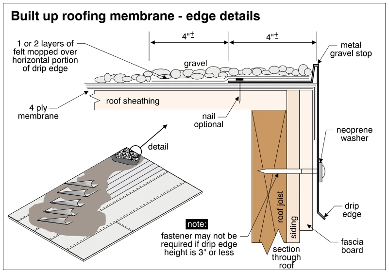
The illustration shows a section through the perimeter of a gravel-surfaced, four-ply built-up roof, with a small perspective inset illustrating the layered roofing assembly. Metal edge flashing extends horizontally into the roofing, rises at the perimeter to form a gravel stop, and turns down over the fascia to a projecting drip edge. One or two layers of felt are mopped over the horizontal portion of the flashing, with two approximately 4-inch dimensions indicated across the edge detail. An optional nail is shown through the horizontal flange, and a face fastener with a neoprene washer secures the vertical leg. A note states that the fastener may not be required if the drip edge height is 3 inches or less; roof sheathing, a roof joist, siding, and the fascia board are identified below.
 0108
0108Built up roofing membrane - curbed edge
· p. 26
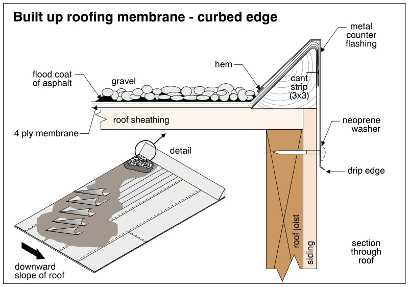
The illustration shows a section through the curbed edge of a built-up roof with a four-ply membrane, an asphalt flood coat, and gravel surfacing over roof sheathing. The membrane turns upward along a triangular 3x3 cant strip at the perimeter. Hemmed metal counterflashing covers the raised edge and extends down the exterior face, where a fastener with a neoprene washer and an outward-turned drip edge are shown. Roof sheathing, a roof joist, and siding are identified beneath the edge assembly. An inset perspective shows the layered membrane construction and indicates the downward slope of the roof.
 0109
0109Modified bitumen roof/wall flashing
· p. 26
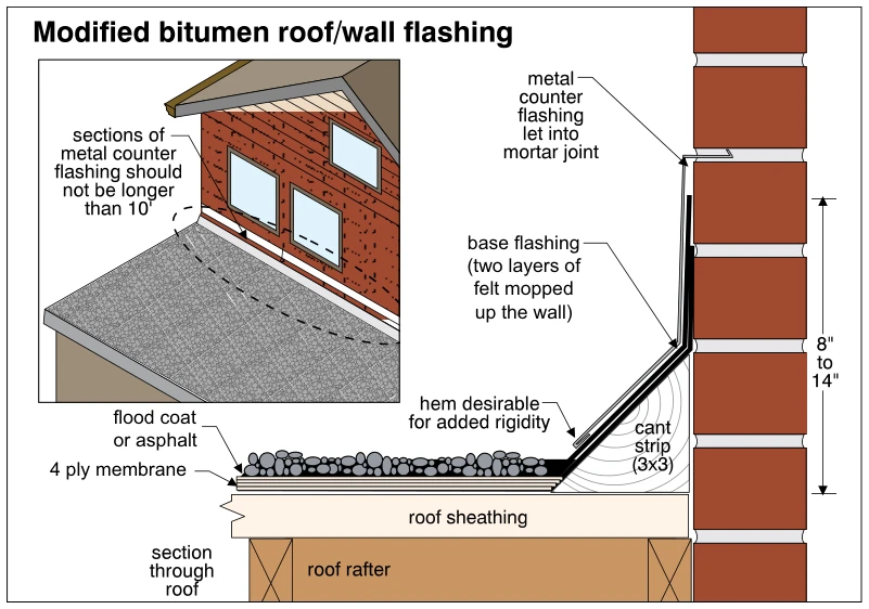
The illustration shows a low-slope roof meeting a brick wall, with an overview and an enlarged flashing section. A four-ply roof membrane and flood coat or asphalt lie over roof sheathing supported by a roof rafter. Two layers of felt base flashing extend up the wall over a 3-by-3 cant strip at the roof-wall transition. Metal counter flashing is let into a mortar joint and overlaps the base flashing; a hem is identified as desirable for added rigidity. The detail indicates a flashing height of 8 to 14 inches and limits metal counter flashing sections to 10 feet in length.
 0111
0111Alternative attachment method for counter flashing
· p. 27
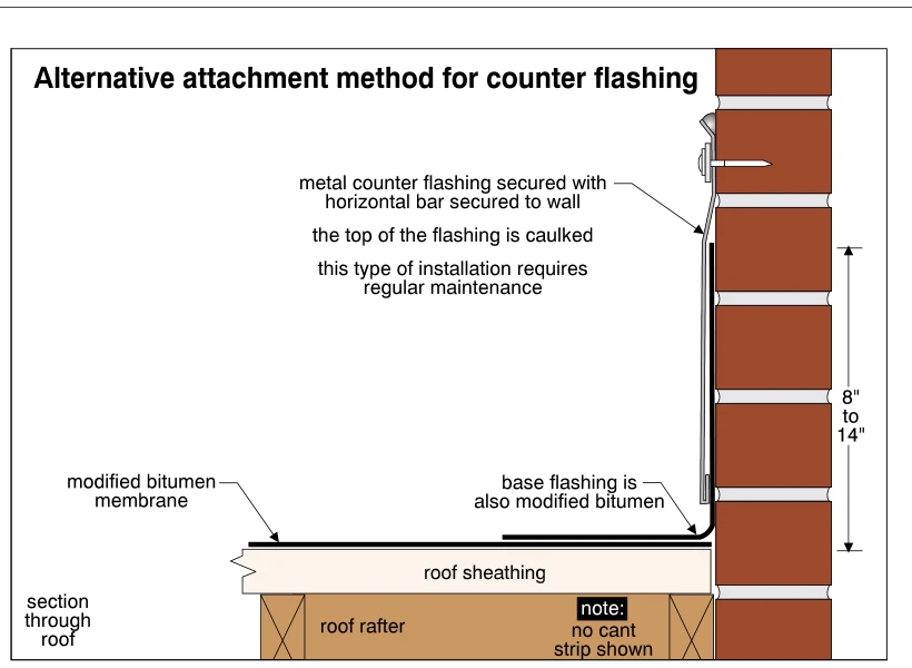
A section through a flat roof at a brick wall shows a modified bitumen roof membrane over roof sheathing supported by a roof rafter. Modified bitumen base flashing extends across the roof edge and turns up the wall, with metal counter flashing overlapping its vertical leg. The counter flashing is surface-mounted using a horizontal bar secured to the wall, and its top is caulked. A vertical dimension indicates 8 to 14 inches above the roof surface. Annotations state that this installation requires regular maintenance and that no cant strip is shown.
 0112
0112Lower quality built-up flat roof/wall flashing
· p. 27
The illustration shows a section through a gravel-surfaced built-up flat roof where it meets a brick wall. A four-ply membrane lies over roof sheathing supported by a roof rafter and turns upward over an angled support at the wall. Metal counter flashing is nailed and caulked to the wall, with these attachment and sealing locations identified as potential water entry points. The counter flashing lacks a hem for rigidity, and exposed membrane at the transition is identified as deteriorating quickly. A large red prohibition symbol marks the assembly as a lower-quality flashing practice.
 0113
0113EPDM (or PVC) roof/wall flashing
· p. 27
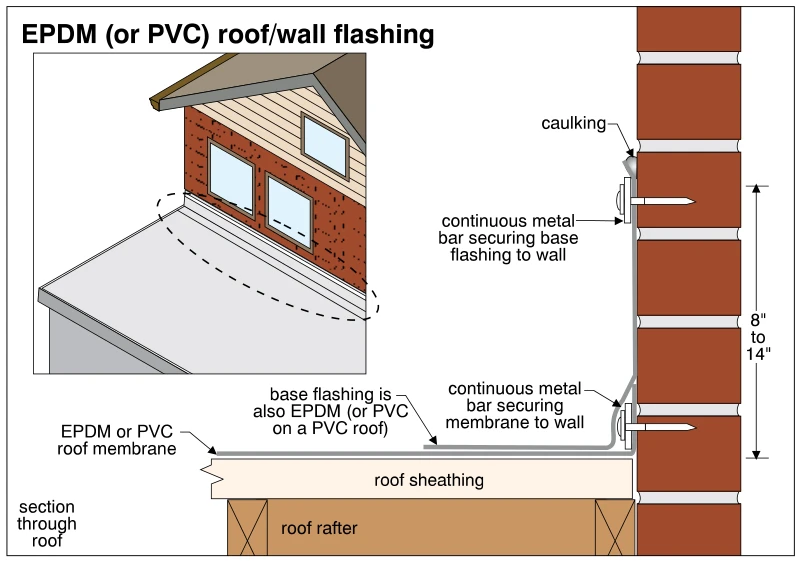
The illustration shows a low-slope membrane roof meeting a brick wall, with an inset locating the flashing along the roof-to-wall junction. In section, the EPDM or PVC roof membrane lies over roof sheathing supported by a roof rafter and is secured at the wall with a continuous metal bar. Matching membrane base flashing overlaps the roof membrane and extends up the wall, where a second continuous metal bar secures its upper termination. Caulking seals the top of the wall flashing, and a vertical dimension indicates a flashing height of 8 to 14 inches above the roof. No defects are depicted.
 0114
0114Through-wall flashings
· p. 27
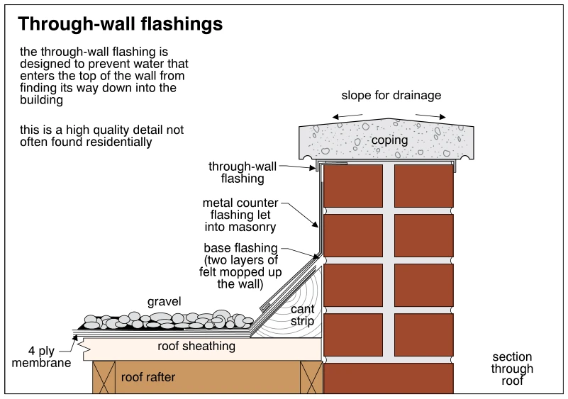
The illustration shows a section through a gravel-surfaced flat roof where it meets a masonry parapet wall. Through-wall flashing extends beneath the coping, which slopes for drainage on both sides. Metal counterflashing let into the masonry overlaps the base flashing, identified as two layers of felt mopped up the wall. A cant strip supports the sloping transition between the four-ply roof membrane and the wall, above roof sheathing and a roof rafter. The annotations describe through-wall flashing as a high-quality detail intended to keep water entering the top of the wall from traveling down into the building.
 0115
0115Metal clad parapet wall
· p. 27
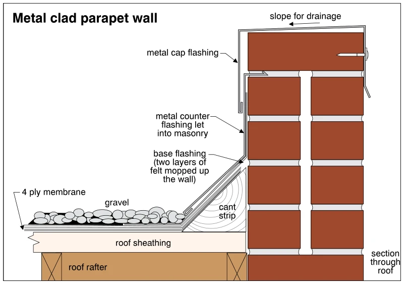
The illustration shows a section through a gravel-surfaced built-up roof meeting a masonry parapet wall. A four-ply membrane lies over roof sheathing supported by a roof rafter. At the wall, a cant strip supports the sloped transition beneath base flashing consisting of two layers of felt mopped up the wall. Metal counter flashing let into the masonry overlaps the base flashing, while metal cap flashing covers the parapet top and extends down its sides. The cap slopes toward the roof for drainage.
 0116
0116Chimney cap details
· p. 27
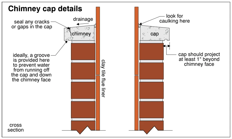
The illustration shows a cross section of a masonry chimney with a cap surrounding a clay tile flue liner that extends above it. The cap slopes outward for drainage and should project at least 1 inch beyond the chimney face. An underside groove near the cap edge acts as a drip to prevent runoff from flowing down the masonry. Annotations direct inspection for caulking at the cap-to-liner junction and sealing of cracks or gaps in the cap.
 0117
0117Skylight in flat roof
· p. 28
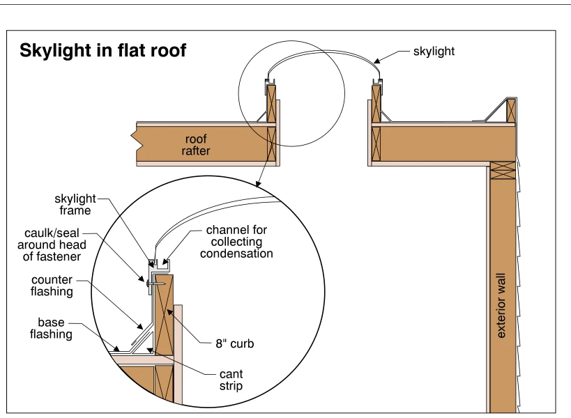
The illustration shows a domed skylight mounted on a raised curb in a flat roof, with roof framing and an exterior wall shown in section. An enlarged detail illustrates the skylight frame, an 8-inch curb, and the flashing assembly at the curb-to-roof junction. Base flashing extends from the roof surface up the curb over a cant strip, with counter flashing overlapping its upper edge beneath the skylight frame. The detail calls for sealing around the head of the frame fastener and shows a channel in the frame for collecting condensation.
 0118
0118"Stack jack" plumbing stack flashing
· p. 28
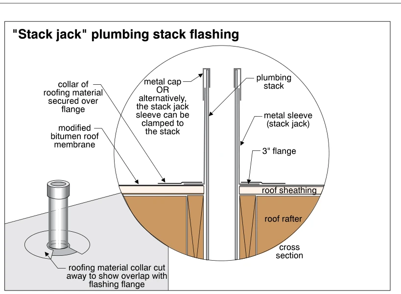
The illustration shows a plumbing stack penetrating a modified bitumen flat roof, with an enlarged cross section of the stack jack flashing. A metal sleeve surrounds the stack and terminates in a 3-inch flange at the roof surface. A collar of roofing material is secured over the flange to integrate the flashing with the roof membrane. The top of the sleeve is protected by a metal cap, with clamping the sleeve to the stack noted as an alternative. Roof sheathing and rafters are shown below the membrane, and a small perspective view has the roofing collar cut away to reveal its overlap with the flange.
 0119
0119Cone-style plumbing stack flashing
· p. 28
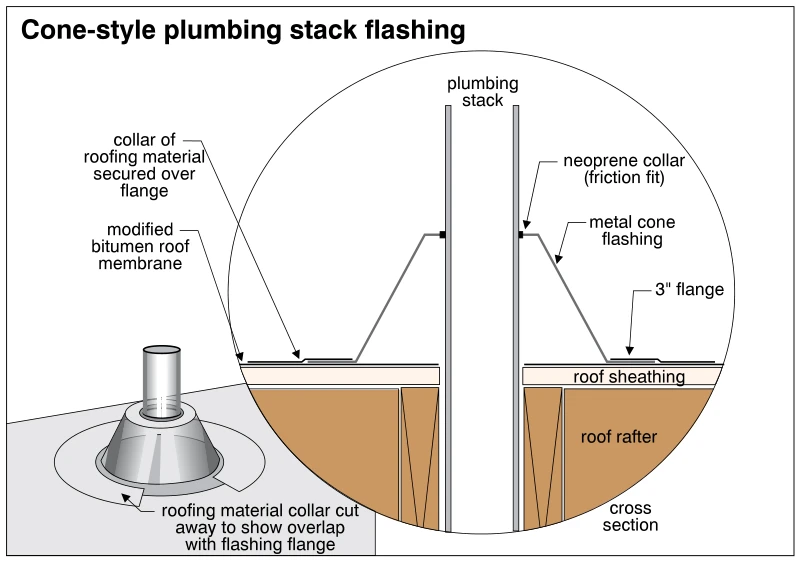
The illustration shows cone-style flashing around a plumbing stack penetrating a modified bitumen roof, with a perspective view and an enlarged cross section. The metal cone surrounds the stack and terminates at a friction-fit neoprene collar. Its base extends onto the roof as a 3-inch flange, covered by a collar of roofing material secured over the flange. A cutaway in the perspective view exposes this overlap, while the cross section shows the roof sheathing and rafters beneath the membrane.
 0120
0120Pitch pans for irregular roof penetrations
· p. 28
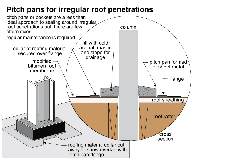
A perspective view and enlarged cross section show a pitch pan sealing an irregular column penetration through a modified bitumen roof. The sheet-metal pan surrounds the column and has an outward flange overlapped by a collar of roofing material. Cold asphalt mastic fills the pan, with its surface sloped away from the column for drainage. The cross section shows the roof membrane above sheathing and roof rafters. Notes describe pitch pans as a less-than-ideal sealing approach with few alternatives and state that regular maintenance is required.
 0121
0121Flat roof drainage systems
· p. 28
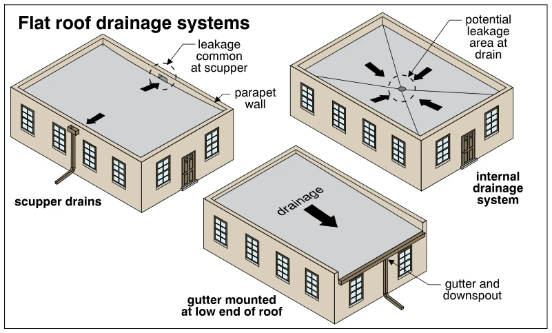
Three building diagrams illustrate alternative flat-roof drainage arrangements. The scupper arrangement drains through openings in parapet walls, with an exterior downspout shown and a callout identifying leakage as common at the scupper. The internal drainage arrangement directs water toward a central roof drain, where a dashed outline marks a potential leakage area. The third arrangement slopes toward an open roof edge with a gutter mounted at the low end and an exterior downspout. Bold arrows indicate the direction of roof drainage.
 0122
0122Drain in modified bitumen roof
· p. 28
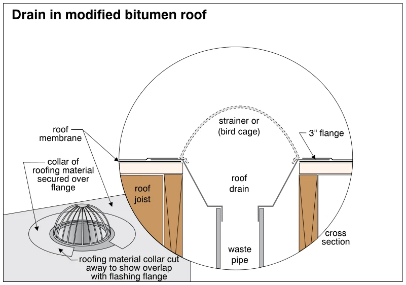
The illustration shows a drain in a modified bitumen flat roof, with a surface view and an enlarged cross section. A domed bird-cage strainer covers the drain opening, which connects to a waste pipe below. The drain's 3-inch flange extends onto the roof assembly, and a collar of roofing material is secured over it. A cutaway in the surface view exposes the collar's overlap with the flashing flange. Roof joists are shown beneath the roof on either side of the drain.
 0123
0123Flat roof draining onto sloped roof
· p. 29
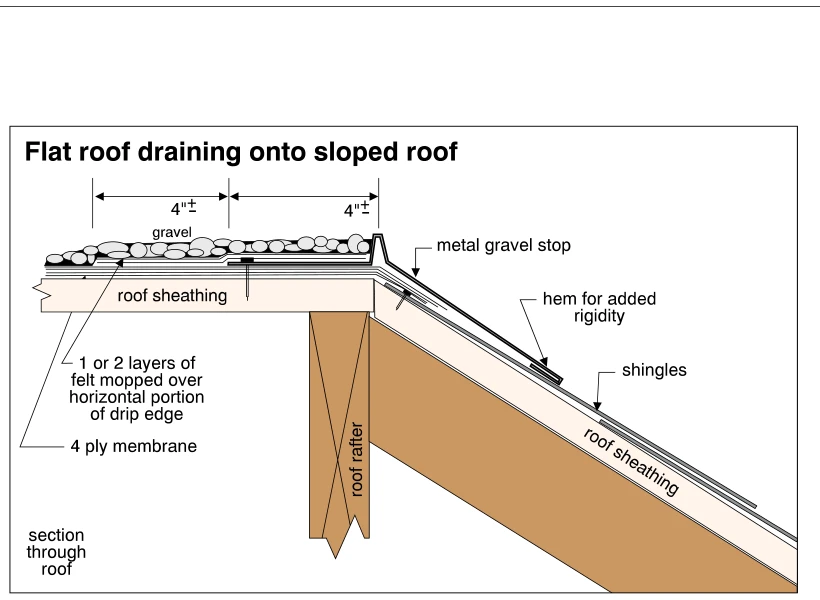
The section shows a gravel-covered, four-ply flat roof draining onto an adjacent shingled sloped roof. A metal gravel stop has a horizontal flange integrated into the flat roof membrane, a raised edge to retain gravel, and a sloping apron extending over the shingles. One or two layers of felt are mopped over the horizontal portion of the drip edge, and the apron has a hem for added rigidity. Roof sheathing and supporting roof framing are shown beneath the two roof surfaces. The illustration presents the flashing arrangement without depicting a defect.
 0124
0124Sloped roof draining onto flat roof
· p. 29
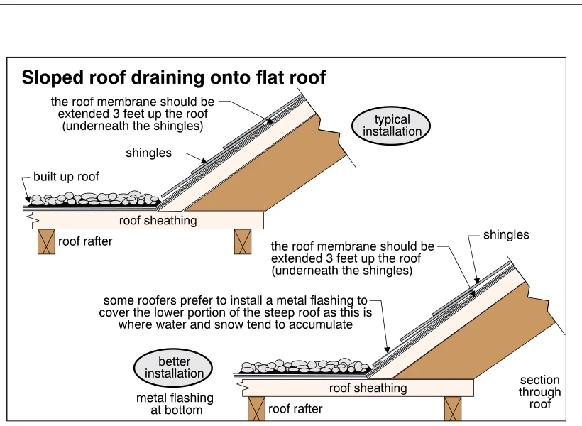
Two roof sections compare typical and improved details where a shingled sloped roof drains onto a gravel-surfaced built-up flat roof. Both details specify extending the flat-roof membrane 3 feet up the slope underneath the shingles. The typical installation shows shingles continuing down toward the roof transition. The better installation adds metal flashing over the lower portion of the steep roof, where the annotation notes that water and snow tend to accumulate. Roof sheathing and supporting rafters are shown beneath the roofing assemblies.