
08Exterior
256 illustrations · printed pages 301-350
Architectural Styles ·Building Shapes and Detailsp. 302
 1700
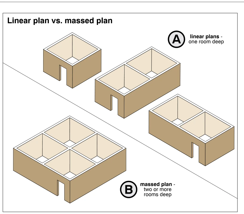
1700Linear plan vs. massed plan
· p. 302
The illustration compares linear and massed building plans using roofless, isometric diagrams showing exterior walls, interior partitions, and entrance openings. Group A depicts a single-room building and two elongated, two-room arrangements, each only one room deep. Group B depicts a compact, four-room arrangement with two rooms in each direction, illustrating a massed plan that is two or more rooms deep. The diagrams compare building shapes and room configurations rather than correct and incorrect construction practices.
 1701
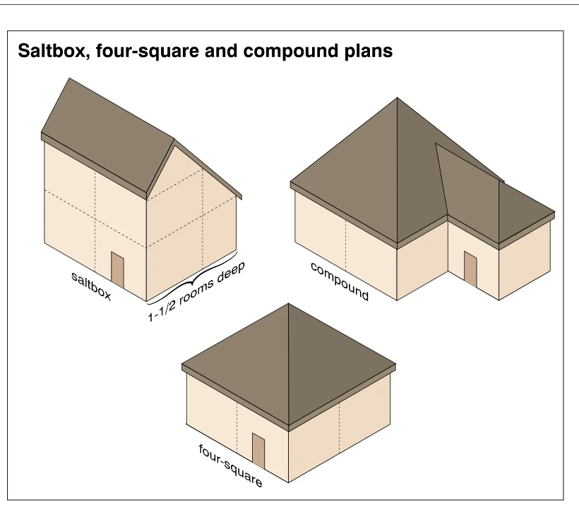
1701Saltbox, four-square and compound plans
· p. 302
Three simplified perspective drawings illustrate saltbox, four-square and compound building forms. The saltbox has an asymmetrical gable roof with one slope extending lower than the other, and a bracket identifies its depth as 1-1/2 rooms. The four-square form has a compact square footprint beneath a pyramidal hip roof. The compound form combines offset building volumes with intersecting hipped roof sections and a recessed wall junction. Dashed lines indicate internal divisions in portions of the buildings; no defects or installation practices are depicted.
 1702
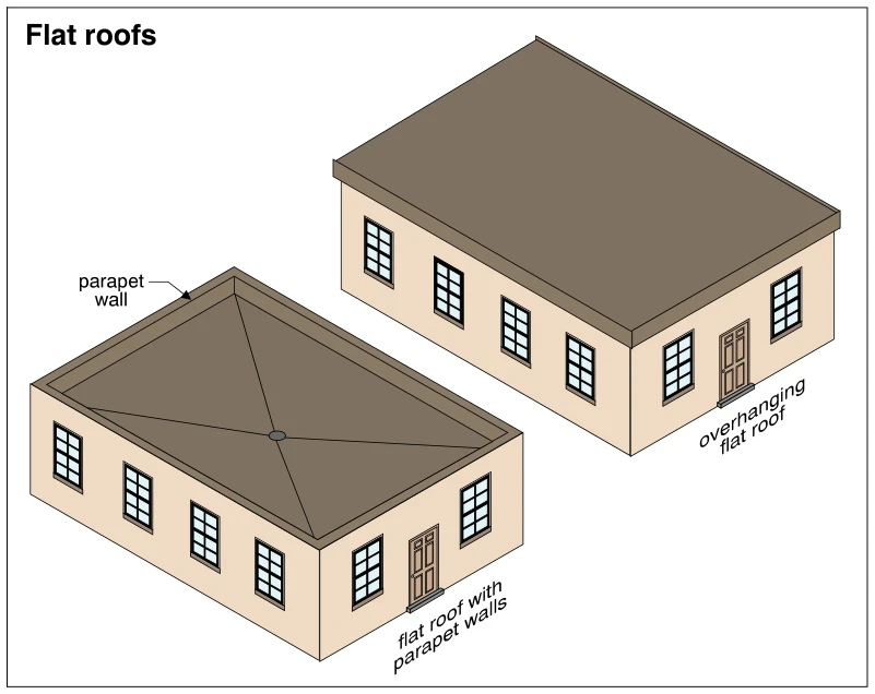
1702Flat roofs
· p. 302
The illustration shows two rectangular buildings with different flat-roof edge configurations. One has an overhanging flat roof that projects beyond the exterior walls. The other has parapet walls enclosing the roof perimeter, with roof planes sloping toward a central drain. Both buildings are shown with exterior windows and an entrance door; no defects are indicated.
 1703
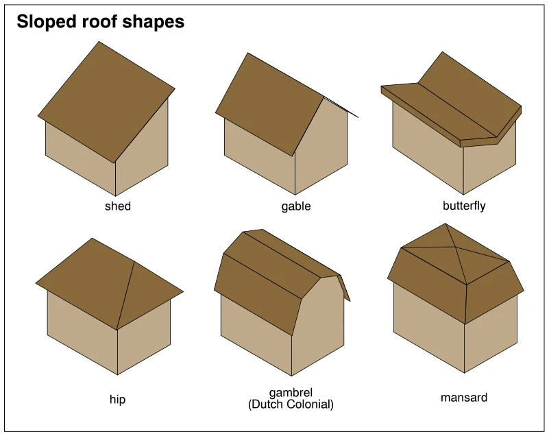
1703Sloped roof shapes
· p. 302
The illustration presents six simplified perspective models of sloped roof shapes on rectangular buildings. The shed roof has a single sloping plane, while the gable roof has two opposing slopes meeting at a ridge. The butterfly roof reverses this arrangement, with slopes falling inward toward a central valley. The hip roof slopes down toward all four sides of the building. The gambrel roof, labeled Dutch Colonial, has steep lower slopes and shallower upper slopes on two sides, while the mansard model shows slope changes around all four sides. These are architectural form examples rather than construction details or depictions of defects.
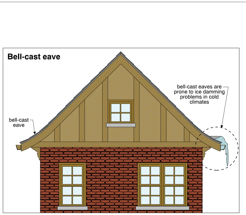 1704
1704Bell-cast eave
· p. 303
The illustration shows the gable end of a house with a steep roof that curves outward to a shallower slope at each bell-cast eave. The gable has vertical siding and a small window above a brick wall with larger windows. A callout identifies the curved eave on the left. A dashed circle highlights ice buildup and a hanging icicle at the right eave, illustrating the noted susceptibility to ice damming in cold climates.
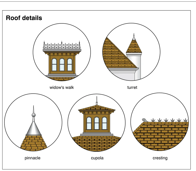 1705
1705Roof details
· p. 303
Five circular vignettes identify architectural roof details. The widow's walk is shown as an elevated flat platform with an ornamental railing above a windowed structure. The turret has a steep pointed roof beside a larger sloping roof, while the pinnacle is a pointed roof-top ornament with a ball and slender spike. The cupola is a small windowed rooftop structure with a shallow pyramidal roof and a finial. Cresting is illustrated as a row of decorative ornaments along a roof ridge; no defects or installation comparisons are shown.
 1706
1706Gable details
· p. 303
Four circular views illustrate architectural details at steeply pitched gable ends. The upper-left view shows exposed truss detailing above a rectangular window. The upper-right view identifies decorative vergeboard or bargeboard along the sloping roof edges and a finial extending above the ridge, with ornamental windows below. The lower-left view shows beam ends projecting from the gable wall around a rectangular window. The lower-right view depicts elaborate gingerbread trim with curved cutouts, spindle-like ornament, and hanging pendants beneath the gable peak. No defects or improper practices are indicated.
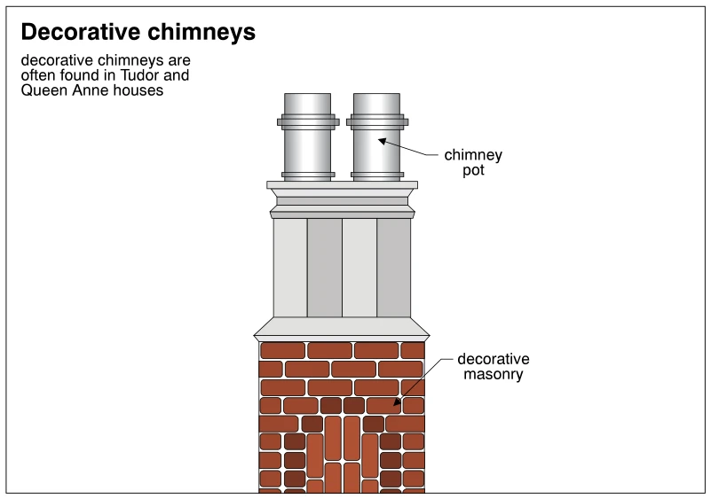 1707
1707Decorative chimneys
· p. 303
The illustration shows a decorative chimney with patterned brick masonry below a contrasting gray upper section. The brickwork combines horizontal courses with vertically oriented bricks to form an ornamental pattern. Projecting ledges and molded bands frame the upper section, which supports two cylindrical chimney pots with raised collars. An annotation identifies decorative chimneys as features often found in Tudor and Queen Anne houses. No defects or improper installation practices are indicated.
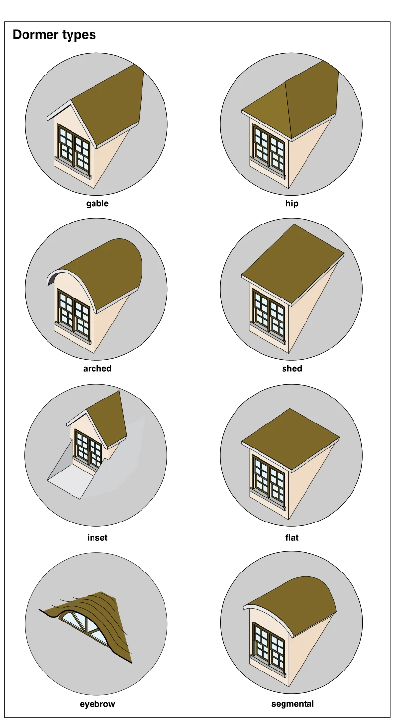 1708
1708Dormer types
· p. 304
Eight perspective diagrams illustrate dormer types distinguished by roof shape and placement. Gable and hip dormers have pitched roof planes, while shed and flat dormers have single roof planes. Arched and segmental dormers have curved roofs above windowed front walls and side cheeks. The inset dormer is recessed into the surrounding roof, with an open recess in front of its windows. The eyebrow dormer has a low, curved window opening beneath a roof surface that sweeps into the surrounding roofing. The illustration identifies architectural forms rather than installation details or defects.
 1709
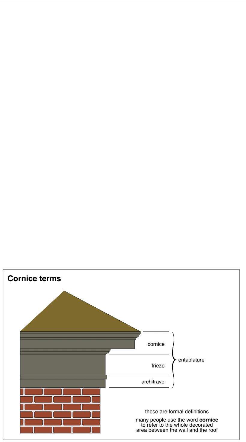
1709Cornice terms
· p. 304
The illustration shows a roof above a layered decorative entablature on a brick wall. The upper projecting portion is identified as the cornice, the broad middle band as the frieze, and the lower band as the architrave. A brace groups all three portions as the entablature. An annotation distinguishes these formal definitions from common usage, in which cornice can refer to the entire decorated area between the wall and roof.
 1710
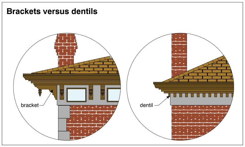
1710Brackets versus dentils
· p. 304
Two circular views compare decorative details beneath the roof cornices of brick buildings. The left view shows widely spaced, shaped brackets beneath a projecting cornice, with rectangular framed panels between them. The right view shows a row of small, closely spaced rectangular dentils beneath the cornice. Both views include a sloping shingled roof and a brick chimney. The illustration distinguishes architectural ornament rather than depicting installation defects.
 1711
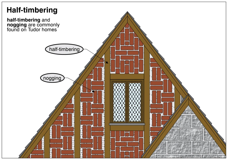
1711Half-timbering
· p. 304
The illustration shows a steeply pitched Tudor-style gable with exposed half-timbering and brick nogging between the timber members. Vertical timbers and sloping members along the gable edges divide the wall into infill panels containing alternating horizontal and vertical brick patterns. A two-light window with diamond-pattern glazing sits within the timber framework. A smaller overlapping gable at the lower right contains rectangular masonry units bounded by sloping timber members. No defects or improper practices are identified.
Architectural Styles ·Windowsp. 305
 1712
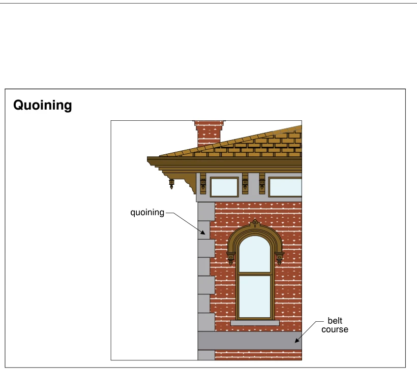
1712Quoining
· p. 305
The illustration shows a portion of a brick building facade with alternating long and short quoin blocks along the exterior corner. A contrasting horizontal belt course crosses the wall below an arched window. The window has an ornamental arched surround and a projecting sill. Above it are small rectangular windows, a bracketed cornice, a sloping shingled roof, and a brick chimney. The drawing identifies architectural details rather than defects or installation practices.
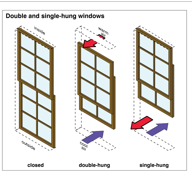 1713
1713Double and single-hung windows
· p. 305
Three diagrams show a closed sash window and the opening arrangements of double-hung and single-hung windows. Each window has two overlapping, vertically arranged glazed sashes with muntins dividing the glazing. The double-hung example has its upper sash lowered and lower sash raised, creating openings at both the top and bottom; arrows indicate warm air leaving above and cool air entering below. The single-hung example retains the upper sash in place while the lower sash is raised, with arrows showing air exchange through the bottom opening. Dashed outlines indicate the window opening and the inside and outside orientation.
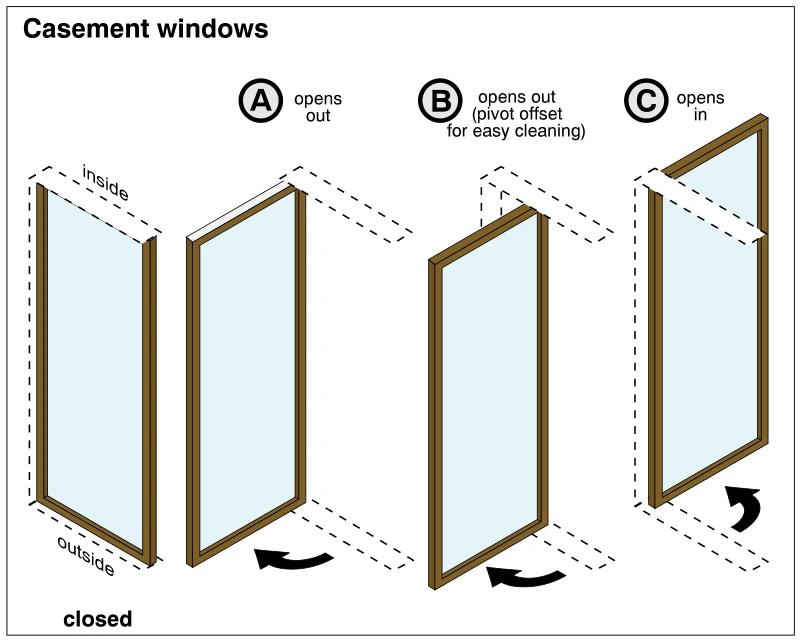 1714
1714Casement windows
· p. 305
The illustration shows a closed casement window and three alternative opening arrangements, identified as A, B, and C. Dashed outlines indicate the window opening, and curved arrows show sash movement. Arrangement A swings outward from the side, while arrangement B opens outward with an offset pivot identified as allowing easy cleaning. Arrangement C swings inward. Inside and outside labels establish orientation at the closed window; no defects are depicted.
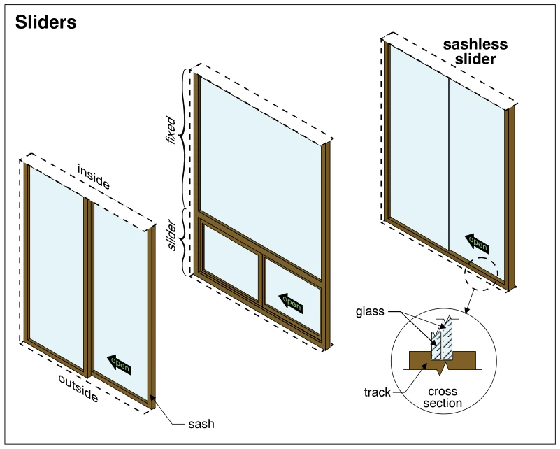 1715
1715Sliders
· p. 305
The illustration shows three horizontal sliding window configurations. The left window has two framed glazed sashes, with inside and outside orientations identified and an arrow indicating leftward opening movement. The center window combines a large fixed upper pane with a pair of smaller sliding sash panels below. The right window is a sashless slider, with glass panels sliding directly in tracks rather than in individual sash frames. An enlarged cross section shows the two glass panels seated in separate grooves in the bottom track.
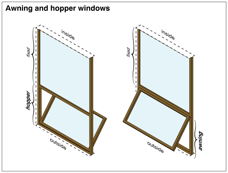 1716
1716Awning and hopper windows
· p. 305
The illustration shows two window assemblies, each with a fixed upper pane and an operable lower sash. The left assembly has a hopper sash hinged at the bottom, with its top tilting inward. The right assembly has an awning sash hinged at the top, with its bottom swinging outward. Inside and outside labels clarify the direction of operation. No defects or installation deficiencies are depicted.
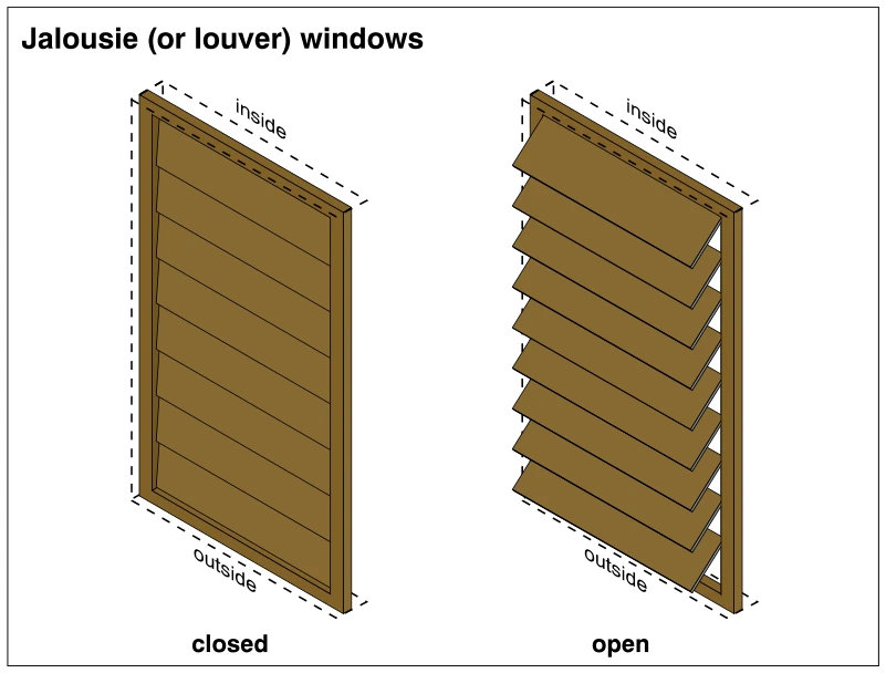 1717
1717Jalousie (or louver) windows
· p. 305
The illustration shows a jalousie, or louver, window in closed and open positions. Each rectangular frame contains a series of horizontal pivoting slats. In the closed position, the slats align to cover the window opening; in the open position, they tilt outward together, leaving ventilation gaps between them. Dashed orientation lines identify the inside and outside of each window. No defects or improper installation practices are depicted.
Architectural Styles ·Specific House Stylesp. 306
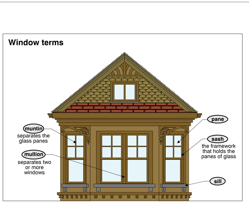 1718
1718Window terms
· p. 306
The illustration shows an ornate gabled exterior elevation with paired central windows, narrow flanking windows, and a small window in the gable. Callouts identify a muntin dividing individual glass panes and a mullion separating the two central windows. Additional arrows identify a pane of glass, the sash framework holding the glass, and the projecting sill beneath a window. The lower windows have divided upper glazing and single-pane lower glazing. This is a terminology diagram rather than a depiction of installation defects.
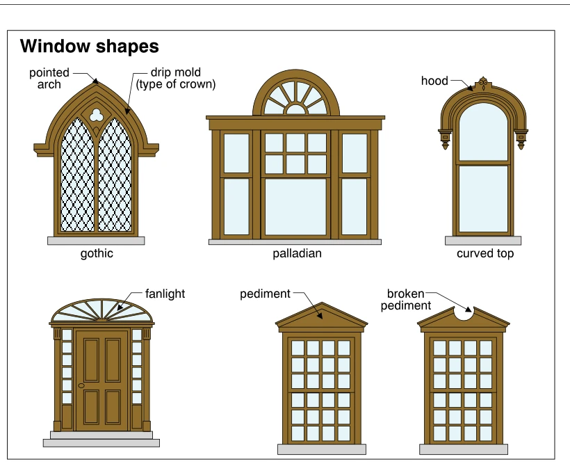 1719
1719Window shapes
· p. 306
The illustration compares six decorative window and entrance configurations. A Gothic window has a pointed arch, diamond-pattern glazing, and an exterior drip mold, while a Palladian arrangement combines a broad central window, narrow flanking windows, and a semicircular glazed top. A curved-top window is framed by an ornamental hood. The entrance example has a paneled door, glazed sidelights, and a semicircular fanlight with radiating glazing bars. Two rectangular multipane windows illustrate an intact triangular pediment and a broken pediment with an opening at its apex. No defects or improper installation practices are depicted.
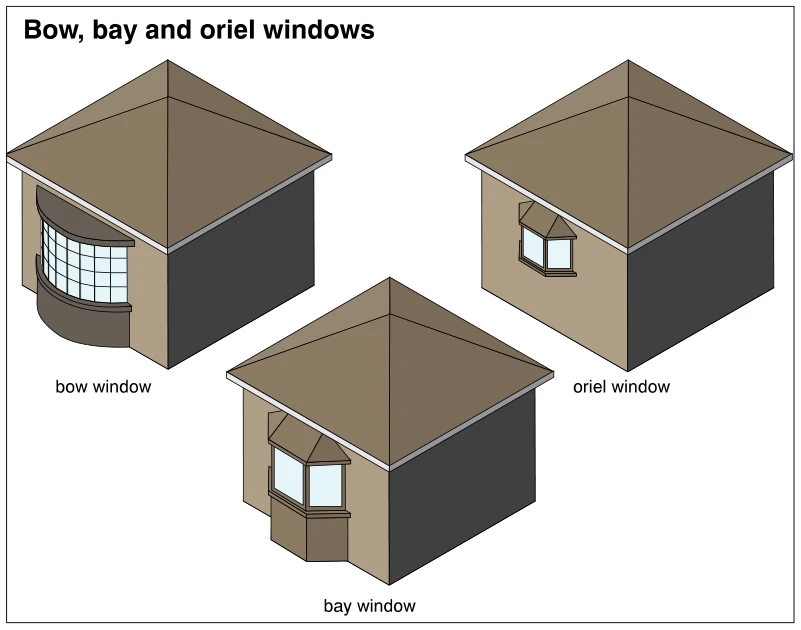 1720
1720Bow, bay and oriel windows
· p. 306
Three simplified house exteriors illustrate bow, bay and oriel windows projecting from exterior walls. The bow window has a rounded profile with multiple glazed divisions and curved upper and lower enclosures. The bay window has an angular profile, a small roof, and an enclosed base extending to the bottom of the wall. The oriel window is a smaller angular projection with a small roof and sill, positioned above the bottom of the wall without an enclosure extending down to grade. The illustration identifies architectural forms rather than installation defects.
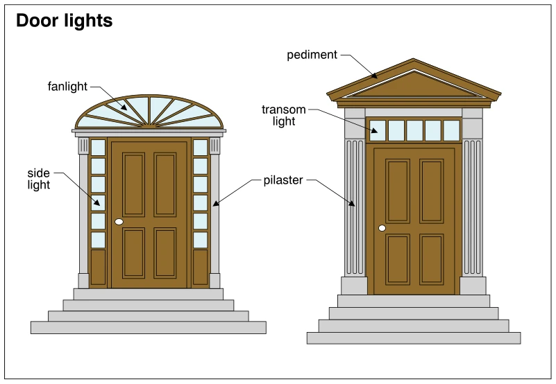 1721
1721Door lights
· p. 306
The illustration shows two paneled entrance doors with different glazing and architectural trim arrangements, each approached by steps. The left entrance has a semicircular fanlight with radial glazing bars above the door and narrow, divided sidelights on both sides. The right entrance has a rectangular, divided transom light above the door and a triangular pediment crowning the surround. Pilasters flank the entrances, with prominent fluting on the right example. The drawing identifies architectural features rather than depicting installation defects.
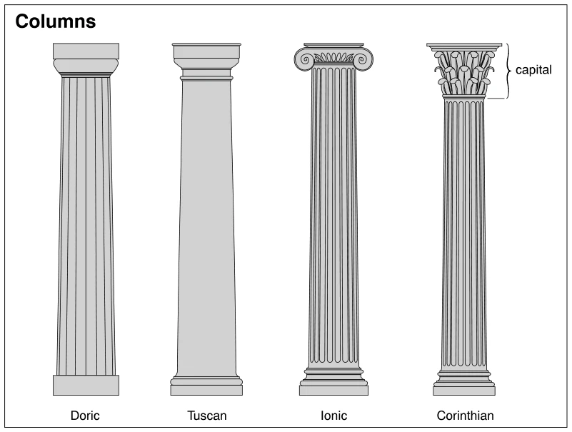 1722
1722Columns
· p. 306
The illustration shows four classical column styles side by side: Doric, Tuscan, Ionic, and Corinthian. The Doric column has a fluted shaft and a simple capital, while the Tuscan column has a smooth shaft with simple molded details at its top and base. The Ionic column has a fluted shaft and a capital with paired spiral scrolls. The Corinthian column has a fluted shaft and an elaborate leaf-decorated capital, identified by a bracket labeled "capital." No defects or installation practices are depicted.
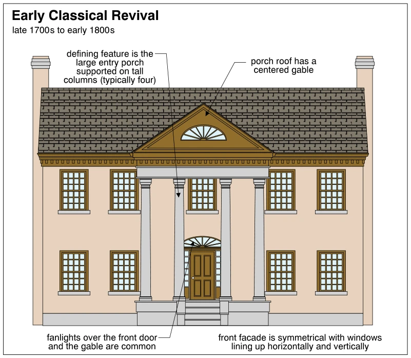 1723
1723Early Classical Revival
· p. 306
The illustration shows the symmetrical front elevation of a two-story Early Classical Revival house, dated late 1700s to early 1800s. A large central entry porch is supported by four tall columns and topped by a centered gable with a semicircular fanlight. The centered front door has sidelights and an overhead fanlight, with steps leading up to the porch. Multi-pane windows align horizontally and vertically across the facade, and chimneys rise at both ends of the main roof. The drawing identifies architectural characteristics rather than inspection defects.
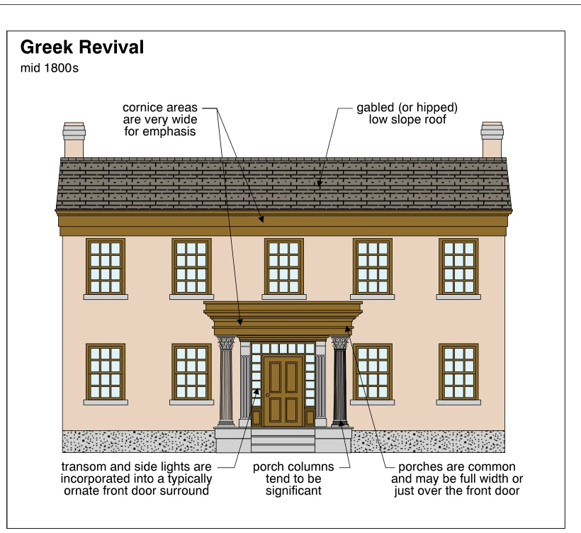 1724
1724Greek Revival
· p. 307
The illustration shows the symmetrical front elevation of a two-story Greek Revival house identified with the mid 1800s. A low-slope roof with chimneys at both ends caps the facade, and broad cornice bands emphasize the roof edge and entrance porch. Multi-pane windows flank a centered entrance, with five windows arranged across the second story. The raised entrance porch has substantial decorative columns and steps leading to a paneled front door framed by sidelights and a transom. The annotations describe characteristic architectural details rather than defects or installation practices.
 1725
1725Georgian
· p. 307
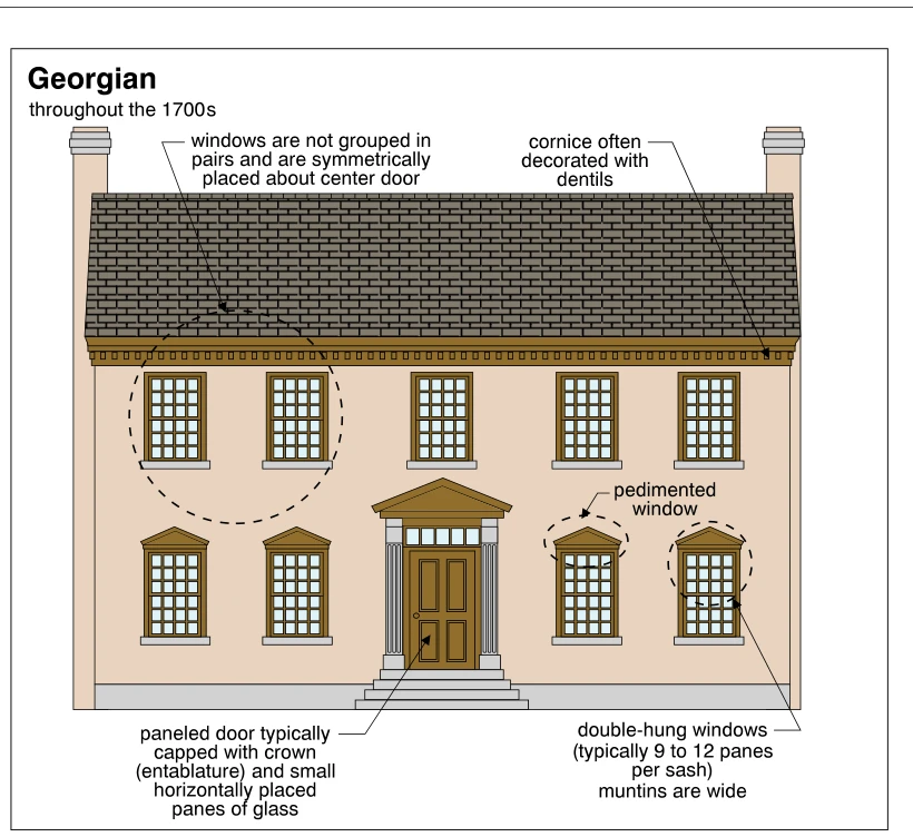
The illustration shows the symmetrical front elevation of a two-story Georgian house, identified as a style found throughout the 1700s. Individual multi-pane windows are evenly arranged around a central paneled entrance, with five windows on the upper floor and two on either side of the entrance below. The entrance has steps, flanking pilasters, a row of small glass panes above the door, and a pedimented crown. The lower-story windows have pedimented heads, and the double-hung windows have wide muntins. A dentil-decorated cornice extends beneath the sloping roof, with a chimney at each end.
 1726
1726Adam
· p. 307
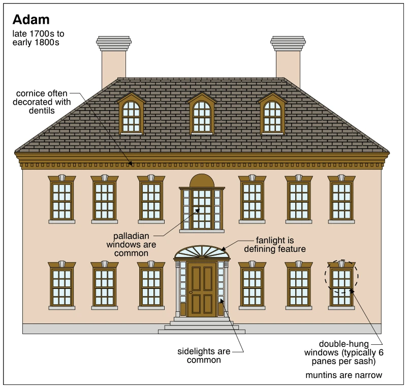
The illustration shows the symmetrical front elevation of an Adam-style house, identified as dating from the late 1700s to early 1800s. The two-story facade has a hipped roof with three arched-window dormers and two chimneys, with dentils decorating the eave cornice. A central paneled entrance door is flanked by sidelights and topped by a semicircular fanlight. Above the entrance is a central window grouping identified as Palladian. The remaining facade windows are double-hung, with narrow muntins and typically six panes per sash; no defects are depicted.
 1727
1727Colonial Revival
· p. 307
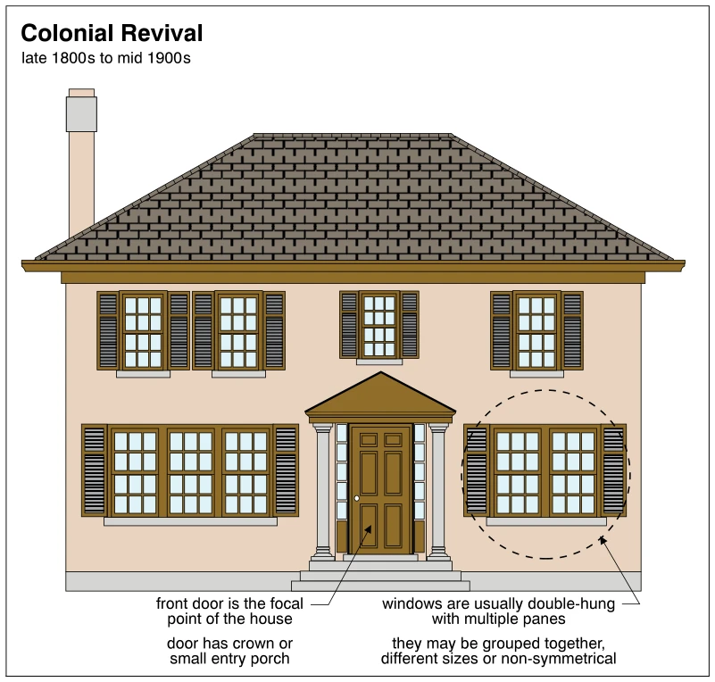
The illustration shows the front elevation of a two-story Colonial Revival house with a hipped, shingle-patterned roof and a chimney at the left. The central paneled front door is emphasized by sidelights, steps, and a small pedimented entry porch supported by columns. Multi-pane windows have flanking louvered shutters and appear individually and in groups of different sizes. A dashed circle highlights the paired lower-right windows, and annotations identify the entrance and window arrangements as characteristic style features. No defects or improper construction practices are depicted.
 1728
1728Italian Renaissance
· p. 308
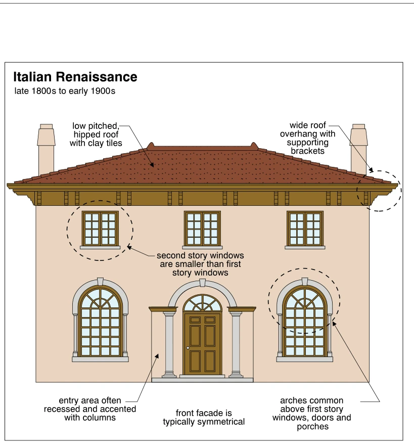
The illustration shows a symmetrical two-story Italian Renaissance house facade identified with the late 1800s to early 1900s. A low-pitched clay-tile hip roof has wide overhangs with supporting brackets and chimneys at either side. Smaller rectangular second-story windows sit above tall, arched first-story windows. The central entry is recessed and accented by columns, an arched surround, and a fanlight above a paneled door. Callouts highlight architectural characteristics rather than defects or installation practices.
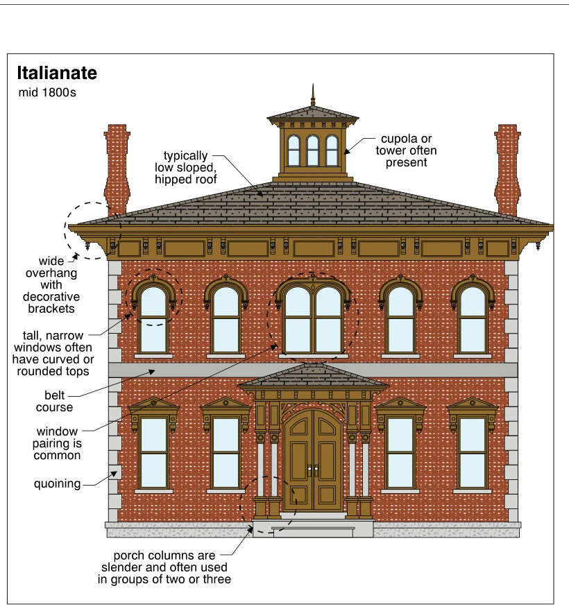 1729
1729Italianate
· p. 308
The illustration shows the front elevation of a symmetrical, two-story Italianate house identified with the mid 1800s. A low-sloped hipped roof has wide, decoratively bracketed eaves, two brick chimneys, and a central windowed cupola. The brick facade features contrasting corner quoining and a horizontal belt course between stories. Tall, narrow upper-story windows have rounded tops, with a paired window centered above the entrance; the lower windows have decorative pedimented surrounds. The central double-door entrance is sheltered by a small hipped porch roof supported on grouped slender columns.
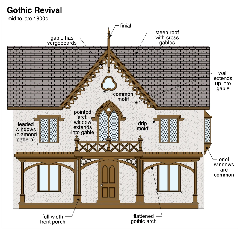 1730
1730Gothic Revival
· p. 308
The illustration shows the front elevation of a Gothic Revival house identified with the mid to late 1800s. A steep roof has a prominent front cross gable with decorative vergeboards and a finial, and the exterior wall extends into the gable. A central pointed-arch window rises into the gable beneath a small trefoil-shaped opening labeled as a common motif. Upper windows have diamond-pattern leaded glazing and drip molds, and a projecting oriel window is shown on the right side. A full-width front porch features posts and flattened Gothic arches, with a short decorative railing centered above the entry.
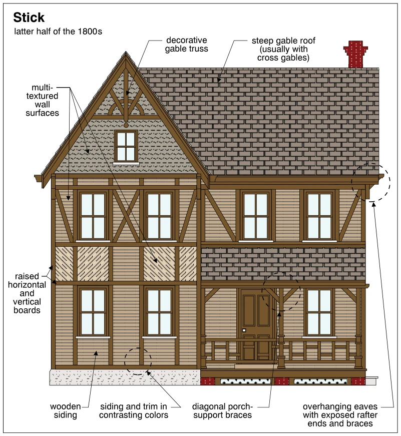 1731
1731Stick
· p. 308
The illustration shows the front elevation of a two-story Stick-style home associated with the latter half of the 1800s. A steep roof includes a prominent front-facing cross gable with a decorative gable truss. Multi-textured exterior wall surfaces are divided by raised horizontal, vertical, and diagonal boards, with contrasting colors distinguishing the siding and trim. A covered front porch has posts, railings, and diagonal support braces, while the roof eaves project outward with exposed rafter ends and braces. Windows, an entry door, a chimney, and the exposed foundation complete the elevation; no defects are identified.
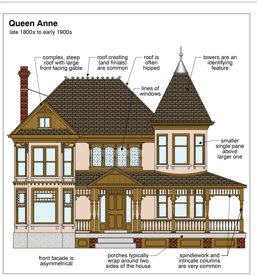 1732
1732Queen Anne
· p. 309
The illustration shows an asymmetrical Queen Anne house with a complex, steep roof combining a hipped main roof, a large front-facing gable, and a prominent tower with a pointed roof. Decorative cresting runs along the main roof ridge, and a finial tops the tower. Windows occur in groups, with the tower windows labeled as having a smaller single pane above a larger one. A porch extends across the front and around the side, featuring turned columns, ornamental spindlework, railings, and a gabled entrance. Additional visible features include a tall masonry chimney, decorative brackets, entrance steps, and contrasting exterior wall treatments; no defects are identified.
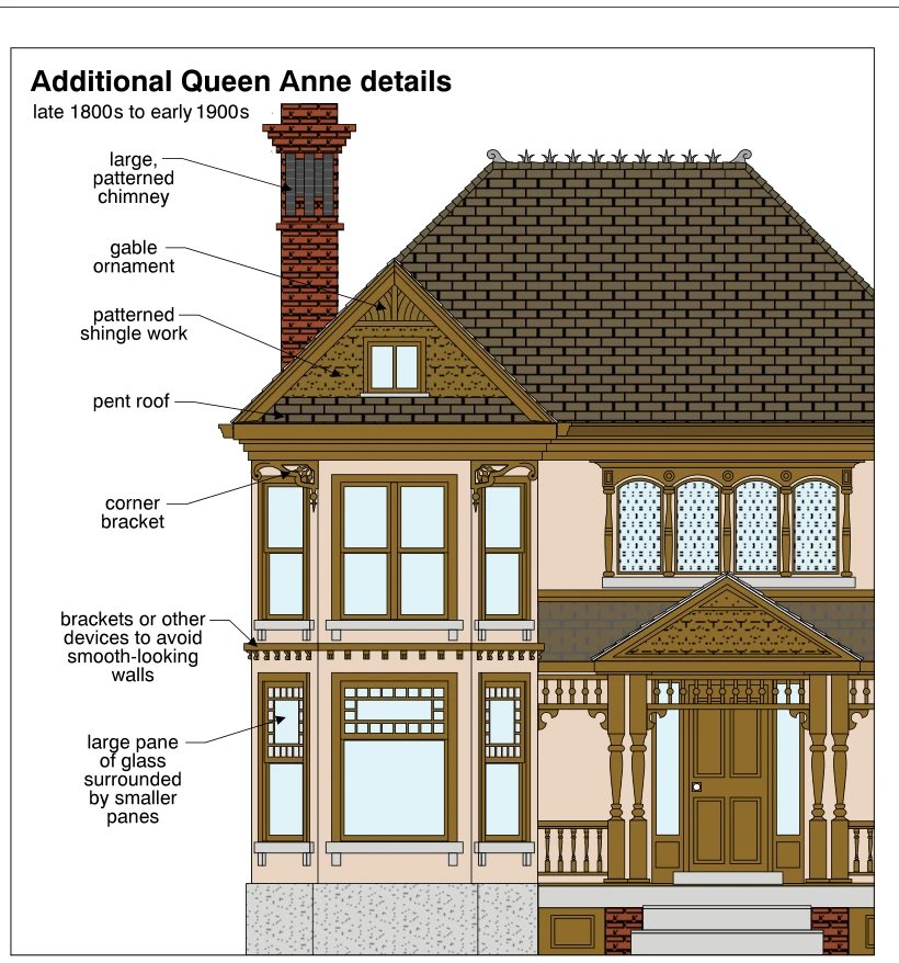 1733
1733Additional Queen Anne details
· p. 309
The illustration shows a partial front elevation of a Queen Anne house, identified as dating from the late 1800s to early 1900s. A large patterned masonry chimney rises beside a decorative front gable with patterned shingles, a gable ornament, and a pent roof across its base. The projecting two-story window bay has ornamental corner brackets and smaller brackets along the division between stories. Lower windows feature large panes of glass bordered by smaller panes. The entrance porch includes a decorated pediment, turned posts, spindlework, and railings, while ornamental cresting follows the main roof ridge. The drawing identifies architectural features rather than defects or installation practices.
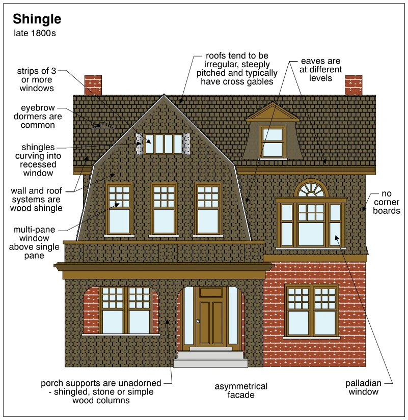 1734
1734Shingle
· p. 309
The illustration shows the asymmetrical front facade of a late-1800s Shingle-style house. Wood shingles cover the roof and much of the walls, with no corner boards and shingles curving into a recessed upper window group. The irregular roof includes a prominent front gable, an eyebrow dormer, a larger gabled dormer, and eaves at different levels. Windows include groups of three or more, multipane upper sashes over single-pane lower sashes, and a Palladian window on the right. A covered entry porch has unadorned shingled supports, while exposed brickwork appears on the lower right facade and two chimneys.
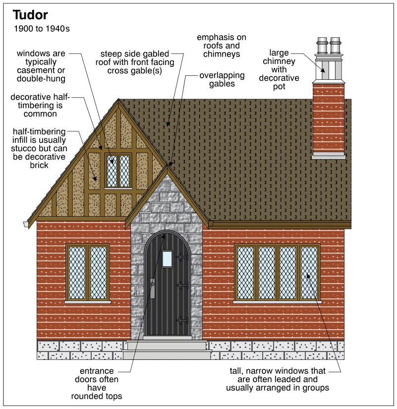 1735
1735Tudor
· p. 309
The illustration shows the front elevation of a Tudor-style home, identified with the period 1900 to 1940s. A steep side-gabled roof has overlapping front-facing cross gables and a large brick chimney with decorative chimney pots. The exterior combines brick walls, decorative half-timbering with textured infill in the larger front gable, and a stone-faced entrance gable. A rounded-top entrance door sits above front steps, and tall, narrow windows with diamond-pattern glazing are arranged in groups. The annotations identify characteristic architectural features rather than inspection defects.
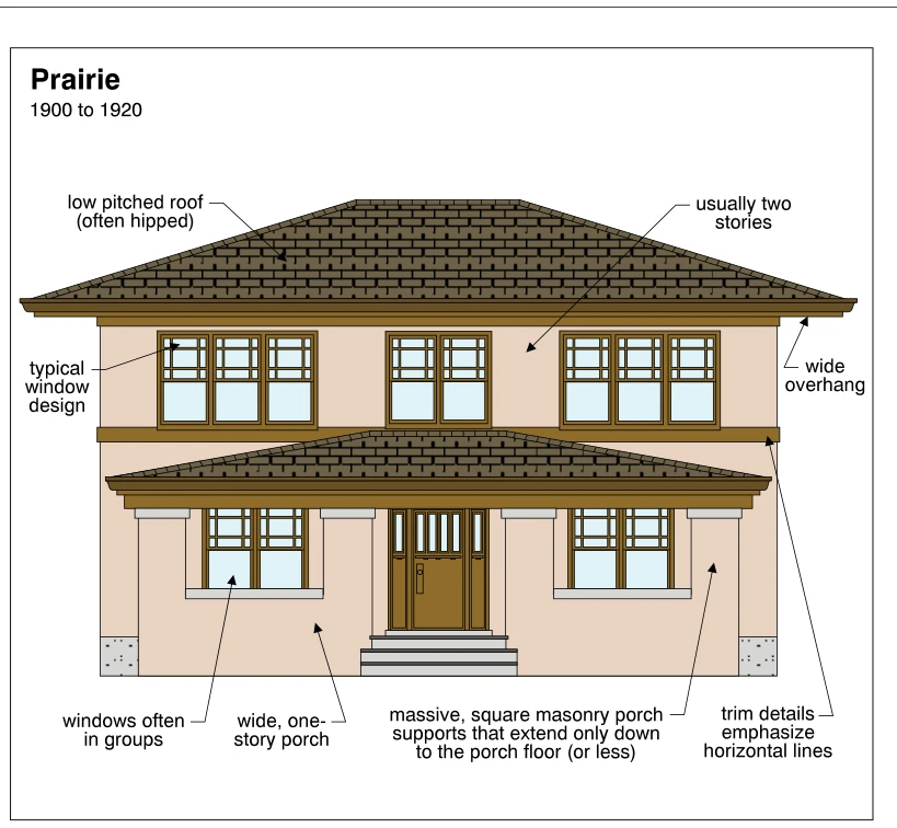 1736
1736Prairie
· p. 310
The illustration shows the front elevation of a two-story Prairie-style home, identified with the period 1900 to 1920. A low-pitched hipped roof with wide overhangs caps the house, and a wide, one-story porch has a similar low-pitched roof. Windows are arranged in groups, with small divided panes in their upper portions and larger panes below. Massive square masonry supports carry the porch roof, framing a central entrance reached by steps. Horizontal trim bands and broad rooflines emphasize the building's horizontal proportions; no defects are depicted.
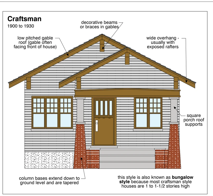 1737
1737Craftsman
· p. 310
The illustration shows the front elevation of a Craftsman house with overlapping, low-pitched front-facing gable roofs and wide overhangs. Decorative beams or braces accent the gables, which are clad in horizontal siding. The covered entry porch has square roof supports resting on tapered brick bases that extend to ground level. Central steps lead to a paneled entry door, with grouped windows on either side featuring divided upper panes. Annotations date the style to 1900–1930 and identify its association with bungalow houses of one to one-and-a-half stories.
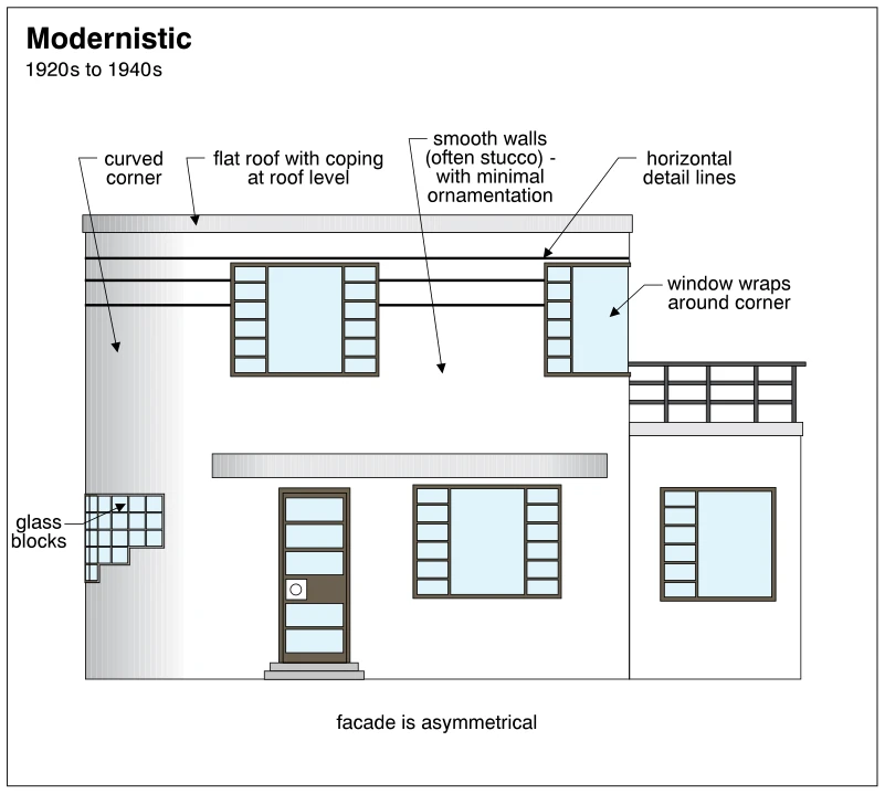 1738
1738Modernistic
· p. 310
The illustration depicts an asymmetrical Modernistic house facade associated with the 1920s to 1940s. The two-story main volume has a flat roof with coping, a curved exterior corner, and smooth walls with minimal ornamentation, identified as often stucco. Horizontal detail lines run across the upper facade, and an upper-story window wraps around the right corner. Glass blocks punctuate the curved left corner, while a glazed entrance door and broad windows occupy the lower facade. A lower volume on the right has a railed roof-level terrace.
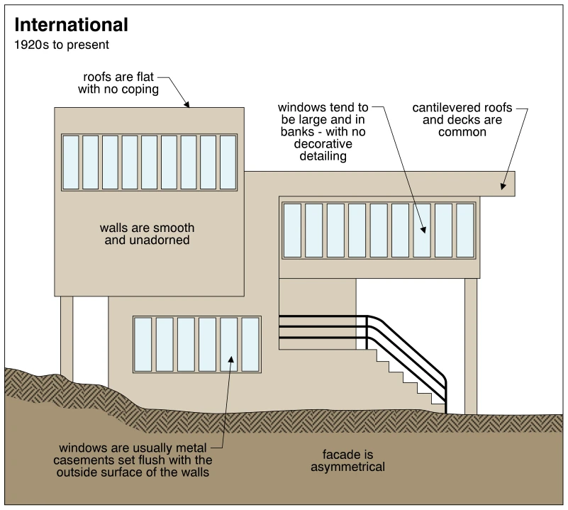 1739
1739International
· p. 310
The illustration depicts an International-style house with an asymmetrical facade composed of rectangular building masses at different heights. Flat roofs are shown without coping, including a projecting cantilevered roof over the right-hand portion. Smooth, unadorned walls contain banks of windows identified as metal casements set flush with the exterior wall surface. An exterior stair and landing with horizontal railings occupy a recessed area beneath the upper story. The annotations describe architectural characteristics rather than identify inspection defects.
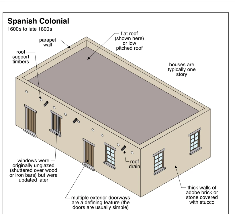 1740
1740Spanish Colonial
· p. 311
The illustration shows a rectangular, one-story Spanish Colonial house with a flat roof enclosed by parapet walls. Thick exterior walls are identified as adobe brick or stone covered with stucco, and roof-support timber ends are visible along the long wall. Projecting roof drains discharge through the exterior wall below the parapet. Multiple simple exterior doorways, a barred window, and divided-light windows illustrate characteristic openings. Annotations date the style to the 1600s through the late 1800s and explain that originally unglazed, shuttered and barred windows were updated later.
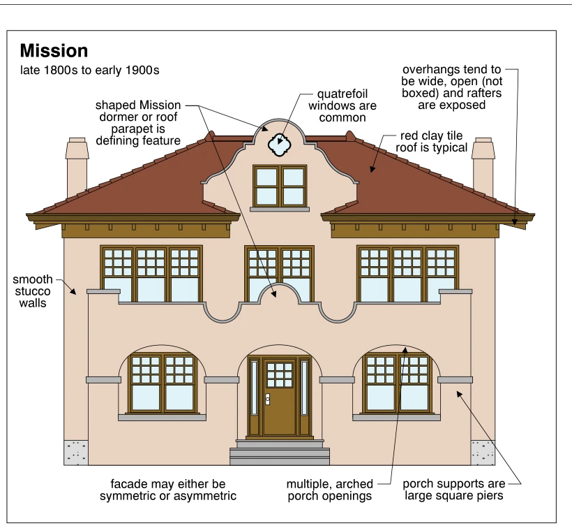 1741
1741Mission
· p. 311
The illustration shows the front elevation of a Mission-style home, identified with the late 1800s to early 1900s. A red clay tile roof has wide, open overhangs with exposed rafters and chimneys at both ends. The central shaped roof parapet contains a quatrefoil window above a paired rectangular window, while a similarly curved parapet caps the porch facade below. Smooth stucco walls, multiple arched porch openings, and large square supporting piers characterize the exterior. The facade shown is symmetrical, with a central entrance and steps flanked by multipane windows.
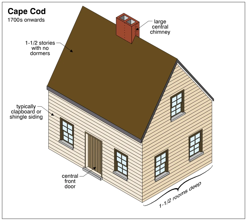 1742
1742Cape Cod
· p. 311
The illustration shows a compact Cape Cod house with a steep gable roof and a large central chimney. It is identified as 1-1/2 stories with no dormers and 1-1/2 rooms deep. A central front door is flanked by multi-pane windows, while the gable end has two lower windows and one upper window. Horizontal siding covers the walls, with an annotation identifying clapboard or shingle siding as typical. The drawing presents architectural characteristics rather than defects or installation practices.
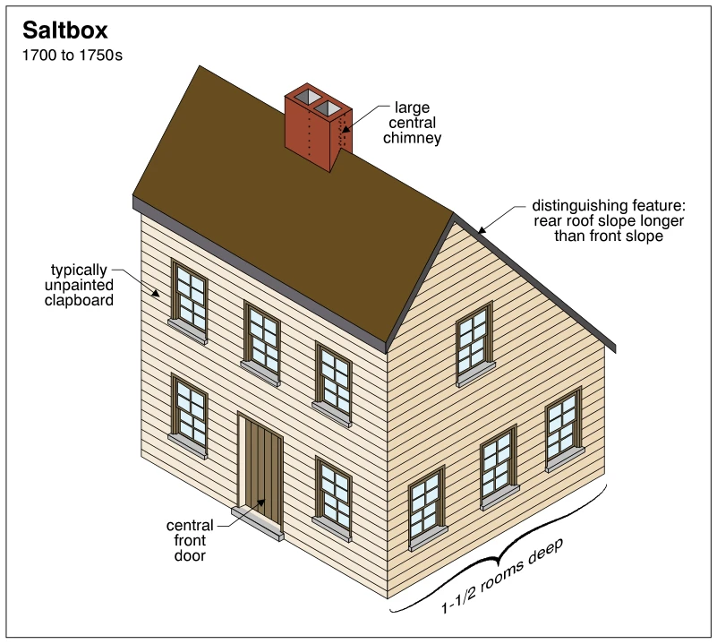 1743
1743Saltbox
· p. 311
The illustration shows a Saltbox-style house identified with the period 1700 to 1750s. Its asymmetrical gable roof has a longer rear slope than front slope, with a large central chimney projecting through the roof. Horizontal clapboard siding covers the walls, and the front elevation has a central entrance and two levels of multipane windows. The side elevation shows the extended rear roof profile, and a bracket identifies the house as 1-1/2 rooms deep. The drawing illustrates architectural characteristics rather than defects or installation practices.
Exterior Cladding ·Wall Surfaces – Generalp. 312
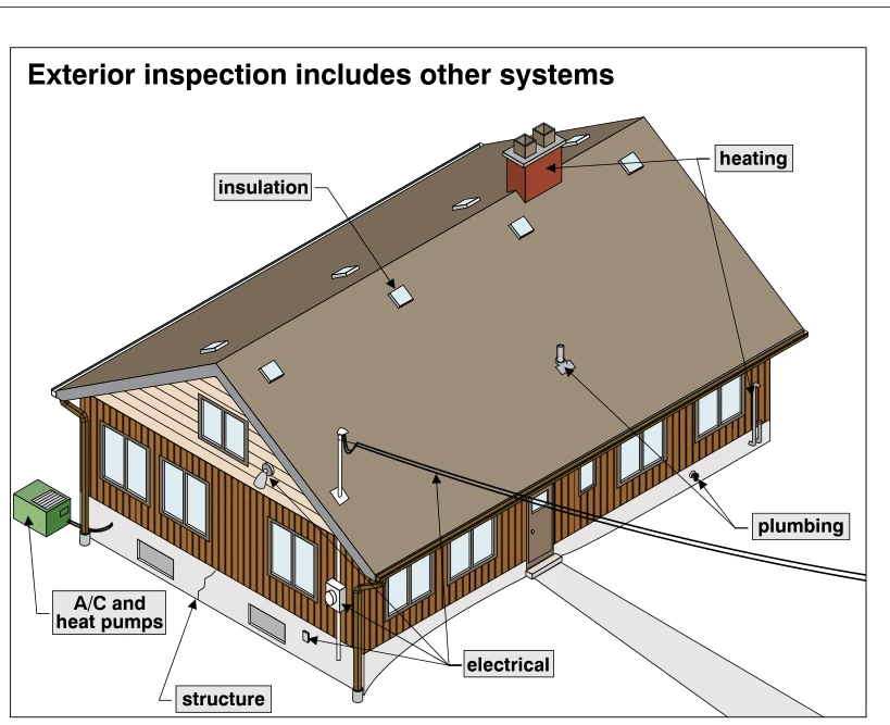 1744
1744Exterior inspection includes other systems
· p. 312
An overview of a house exterior identifies building systems that can be assessed during an exterior inspection. Callouts connect insulation to roof ventilation openings, heating to the chimney and an exterior wall termination, and plumbing to a roof vent and a wall penetration. Electrical features include overhead service wires, a service mast, an exterior meter, and a wall outlet. An outdoor air-conditioning or heat-pump unit sits beside the house, while the structure callout points to a crack in the exposed foundation wall.
 1745
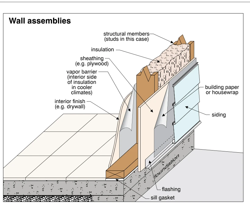
1745Wall assemblies
· p. 312
The illustration shows a cutaway exterior stud-wall assembly supported on a foundation, with layers peeled back to reveal their relationships. Insulation occupies the stud cavities, with a vapor barrier and interior finish on the interior side; the annotation specifies the vapor barrier location for cooler climates. Exterior sheathing is covered by building paper or housewrap and overlapping siding. Flashing is shown at the base of the exterior wall, and a sill gasket separates the wood sill plate from the foundation.
 1746
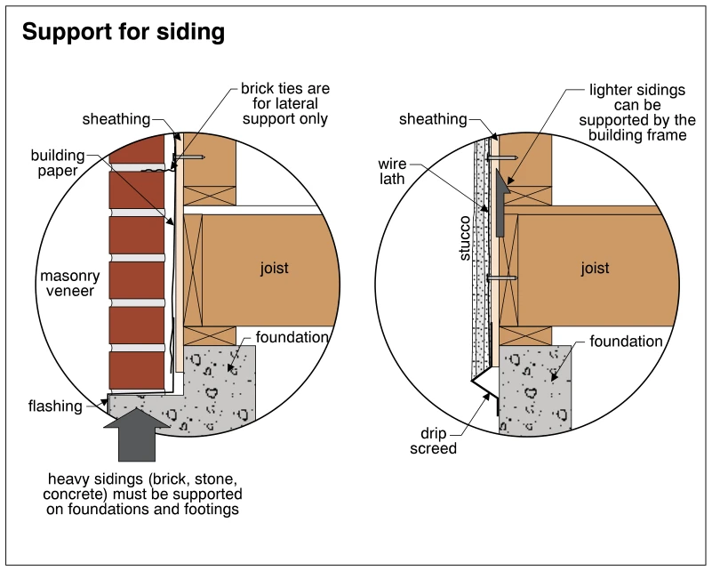
1746Support for siding
· p. 312
Two circular wall-section details compare support requirements for heavy masonry veneer and lighter stucco siding. The left detail shows masonry veneer bearing on a foundation ledge, with flashing at its base and building paper and sheathing behind it. Brick ties connect the veneer to the framing for lateral support only; the annotation states that heavy sidings require support on foundations and footings. The right detail shows stucco over wire lath outside the sheathing, with a drip screed at its lower edge. This lighter cladding is supported by the building frame rather than bearing on a masonry ledge.
 1747
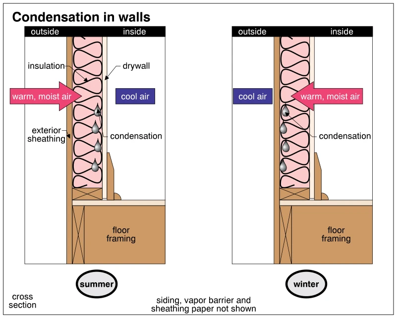
1747Condensation in walls
· p. 312
Two cross sections of an insulated wood-framed exterior wall compare summer and winter condensation conditions. In summer, warm, moist outdoor air moves toward the cool interior, with droplets shown within the wall near the drywall. In winter, warm, moist indoor air moves toward the cool exterior, with droplets shown near the exterior sheathing. Both sections show the wall meeting the floor framing. A note states that siding, vapor barrier and sheathing paper are not shown.
 1748
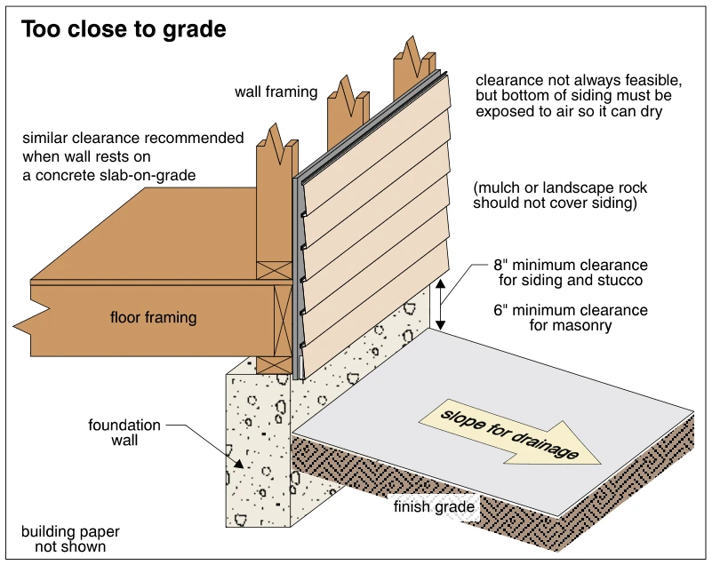
1748Too close to grade
· p. 312
The cutaway shows horizontal lap siding over a framed exterior wall, with floor framing supported by a concrete foundation wall. A vertical dimension indicates minimum clearance above finish grade: 8 inches for siding and stucco and 6 inches for masonry. The ground surface has an arrow indicating slope away from the foundation for drainage. Notes emphasize that the bottom of the siding must remain exposed to air to dry and must not be covered by mulch or landscape rock, even where the recommended clearance is not feasible. Similar clearance is recommended for walls resting on a concrete slab-on-grade, and building paper is explicitly omitted from the drawing.
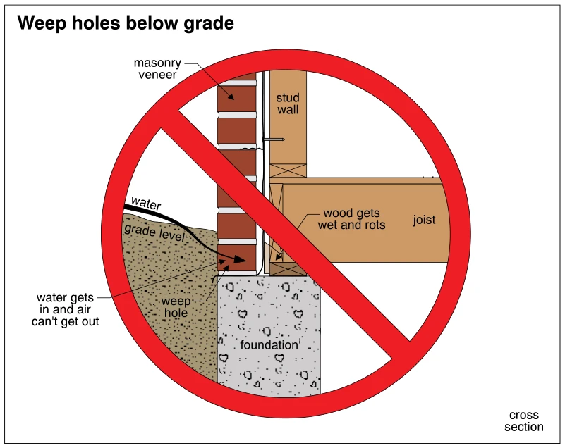 1749
1749Weep holes below grade
· p. 312
The cross section shows a masonry veneer exterior wall beside a wood stud wall and floor joist supported on a concrete foundation. Exterior soil extends above the weep hole at the base of the veneer. An arrow shows surface water entering at this below-grade opening, and an annotation indicates that air cannot get out. Another callout identifies wood framing that gets wet and rots. A large red prohibition symbol marks this arrangement as improper.
Exterior Cladding ·Masonryp. 313
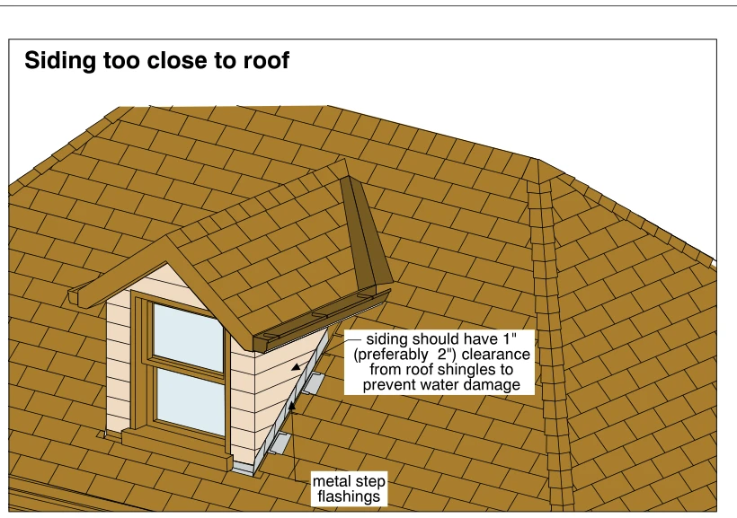 1750
1750Siding too close to roof
· p. 313
The illustration shows a gabled dormer projecting from a shingled roof, with horizontal siding and a window on its front face. Metal step flashings run along the sloped intersection between the dormer sidewall and the main roof. The siding terminates too close to the roof shingles. An annotation specifies 1 inch of clearance, preferably 2 inches, between the siding and shingles to prevent water damage.
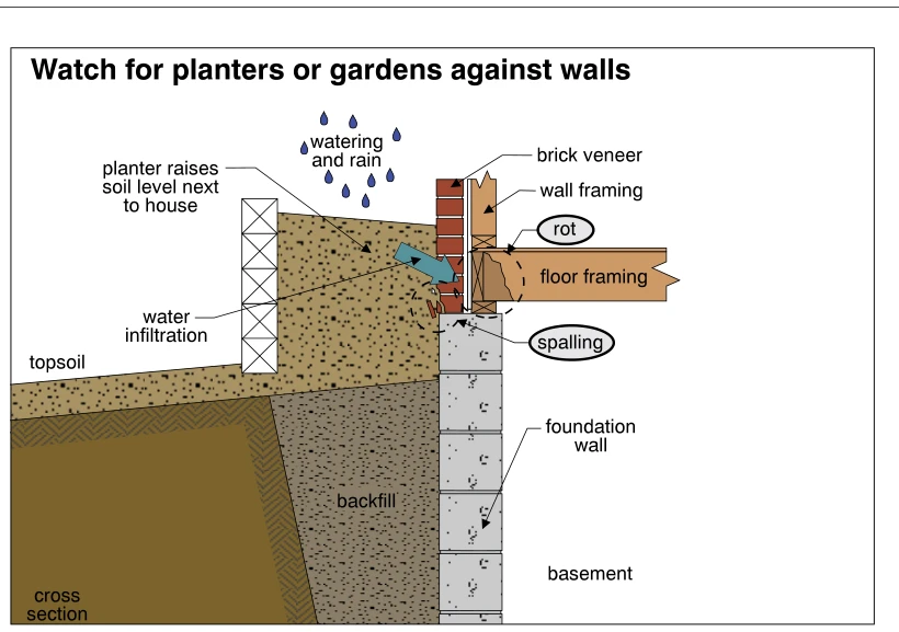 1751
1751Watch for planters or gardens against walls
· p. 313
The cross section shows a raised planter against a house with brick veneer, wood wall and floor framing, and a masonry foundation wall bordering a basement. The planter raises the soil above the adjacent topsoil level and places it against the brick veneer at the framing elevation. Watering and rain wet the planter soil, and arrows indicate water infiltration toward the house. Rot is identified at the wood framing, and spalling is identified near the top of the foundation wall.
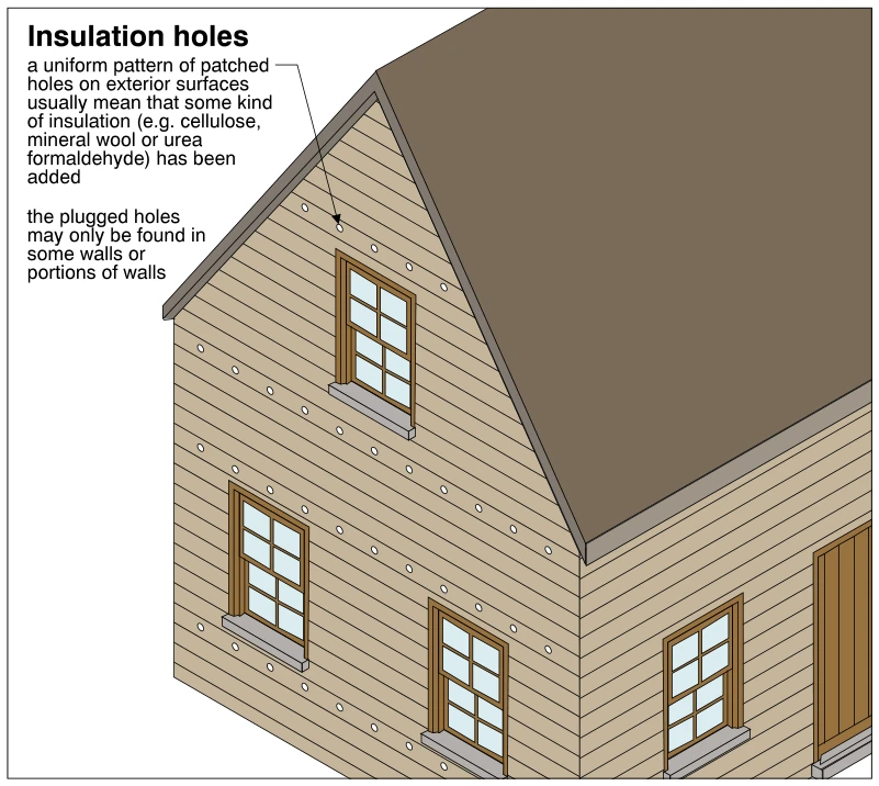 1752
1752Insulation holes
· p. 313
The illustration shows a house with horizontal lap siding, a steep gable roof, windows, and a partially visible exterior door. Repeated small patched holes form regular rows across the gable-end siding, including above and below the windows. An arrow identifies one of these holes, and the annotation explains that this pattern usually indicates insulation added through the exterior wall surface. The notes also explain that plugged holes may occur only on some walls or portions of walls; no corresponding holes are illustrated on the adjacent wall.
 1753
1753Veneer versus solid masonry
· p. 313
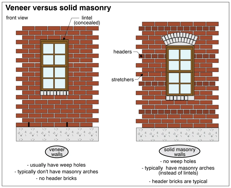
Two front elevations compare brick veneer and solid masonry walls around window openings. The veneer wall shows stretcher faces, a concealed lintel above the window, and weep holes near the base of the brickwork. The solid masonry wall shows header bricks interspersed with stretchers and a masonry arch over the window. Both walls have masonry window sills and rest on concrete bases. Annotations identify typical visible clues for distinguishing the two wall types rather than depicting defects.
 1754
1754Parapet walls prone to damage
· p. 313
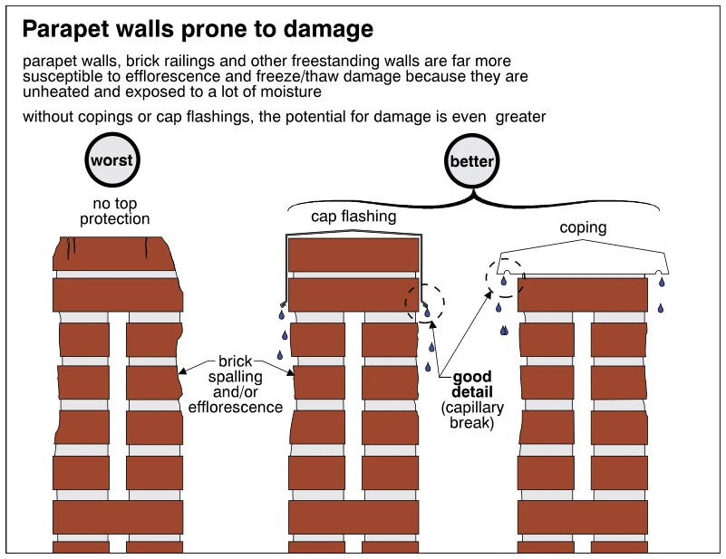
The illustration compares three brick parapet wall sections: an unprotected wall top, a wall with cap flashing, and a wall with coping. The unprotected wall is marked as the worst condition and shows irregular, damaged brick edges. Cap flashing and coping are identified as better protection, with projecting edges and capillary breaks that shed water away from the masonry. Arrows identify brick spalling and/or efflorescence, while water droplets illustrate runoff at the protected wall tops. The text explains that unheated parapets, brick railings, and freestanding walls are particularly susceptible to moisture-related efflorescence and freeze/thaw damage.
 1755
1755Chimney deterioration due to condensation
· p. 313
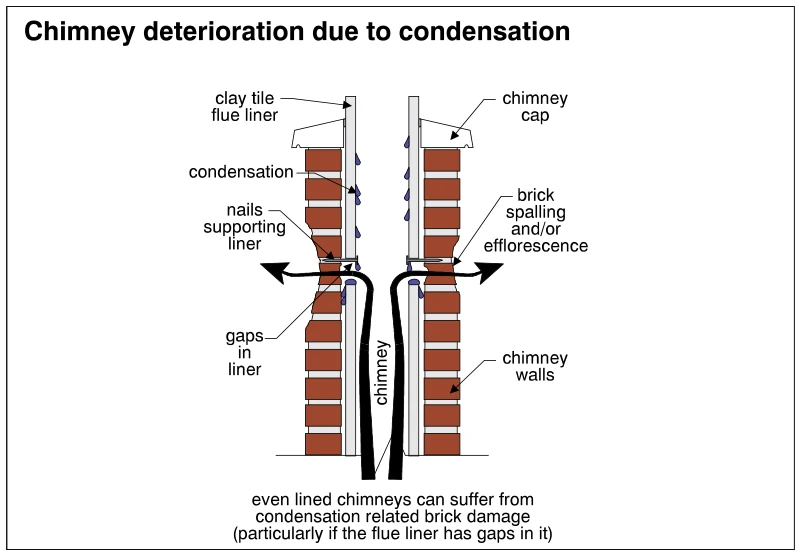
A sectional drawing shows a brick chimney with a clay tile flue liner and a chimney cap. Condensation droplets appear along the liner, and nails support liner sections at a joint with visible gaps. Heavy arrows rise through the flue and turn outward through the gaps toward the masonry. The adjacent bricks are labeled as exhibiting spalling and/or efflorescence. The illustration emphasizes that even lined chimneys can suffer condensation-related brick damage, particularly where the liner has gaps.
 1756
1756Rising damp
· p. 314
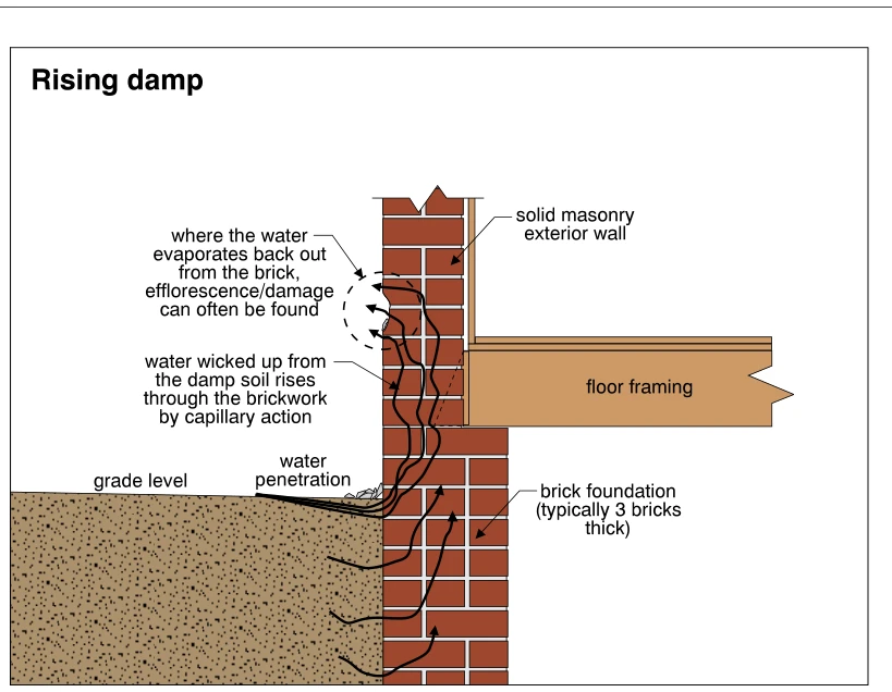
The illustration shows a section through a solid masonry exterior wall supported by a brick foundation, with floor framing extending inward and soil against the exterior below grade. Arrows show water penetrating the foundation from the damp soil and rising through the brickwork by capillary action. Above grade, arrows indicate moisture evaporating from the exterior face of the brick. A dashed outline identifies the evaporation area where efflorescence and masonry damage can often be found.
 1757
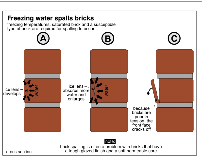
1757Freezing water spalls bricks
· p. 314
Three cross-sectional diagrams show the progression of freeze-related spalling in brick masonry with mortar joints. In stage A, an ice lens develops near the exposed face of a saturated brick, with arrows indicating water moving toward it. In stage B, the ice lens absorbs more water and enlarges. In stage C, the brick's front face cracks off because of its low tensile strength. An annotation identifies freezing temperatures, saturated brick, and a susceptible brick type as necessary conditions, and notes particular susceptibility in bricks with a tough glazed finish and a soft permeable core.
 1758
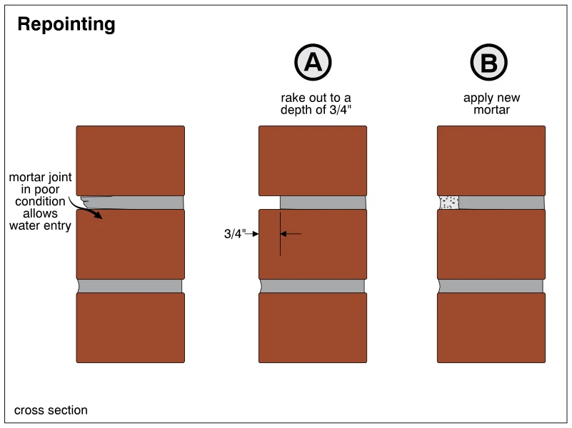
1758Repointing
· p. 314
Three cross-sectional views show a brick masonry mortar joint before and during repointing. The left view identifies a deteriorated mortar joint that allows water entry at the exposed face. Step A shows the joint raked out to a depth of 3/4 inch while retaining mortar farther back. Step B shows new mortar placed in the cleared portion of the joint.
 1759
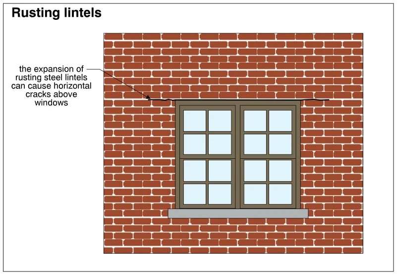
1759Rusting lintels
· p. 314
The illustration shows a brick masonry wall surrounding a paired, divided-light window with a projecting sill. Horizontal cracks run along the mortar joint immediately above the window opening and extend beyond its sides. An arrow points to the cracking, and the annotation attributes it to expansion of rusting steel lintels. The drawing illustrates masonry damage associated with corrosion of the window's steel support lintel.
 1760
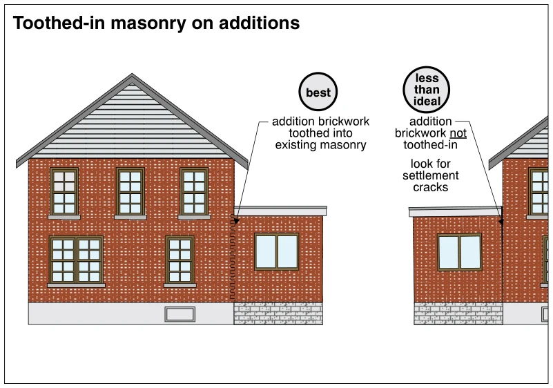
1760Toothed-in masonry on additions
· p. 314
The illustration compares two brick-clad additions attached to existing two-story masonry houses. The preferred detail shows the addition brickwork toothed into the existing masonry, creating an interlocking junction along alternating brick courses. The less-than-ideal detail shows a straight vertical junction where the addition brickwork is not toothed in. An annotation directs inspectors to look for settlement cracks at this junction. Both additions have low, nearly flat roofs, windows, and exposed masonry foundations.
 1761
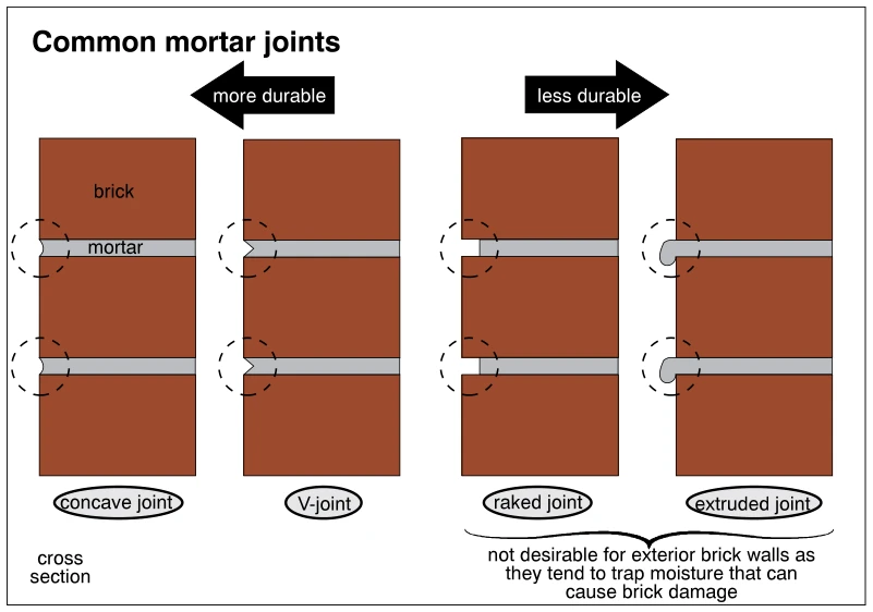
1761Common mortar joints
· p. 314
Four cross sections compare mortar joint profiles between brick courses: concave, V-joint, raked, and extruded. Dashed circles highlight the exposed edges of the mortar joints. The concave profile has a curved recess, the V-joint an angular recess, the raked joint a deep rectangular recess, and the extruded joint projects beyond the brick face. Arrows indicate greater durability toward the left and lower durability toward the right. A bracket groups the raked and extruded joints as undesirable for exterior brick walls because they tend to trap moisture that can cause brick damage.
 1762
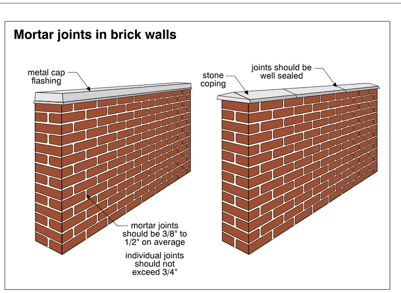
1762Mortar joints in brick walls
· p. 315
The illustration shows two brick walls with staggered mortar joints and alternative protective caps. The left wall is topped with metal cap flashing, while the right wall has segmented stone coping. An annotation specifies that mortar joints should average 3/8 to 1/2 inch, with individual joints not exceeding 3/4 inch. The joints between stone coping sections are identified as requiring good sealing.
 1763
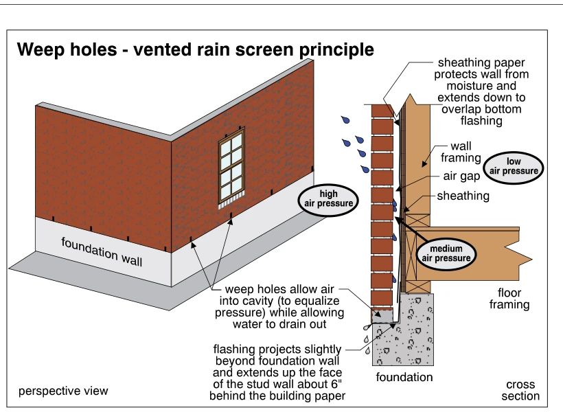
1763Weep holes - vented rain screen principle
· p. 315
The illustration pairs a perspective view of a brick veneer wall with a cross section through the veneer, framed wall, floor framing, and foundation. Weep holes at the base of the veneer admit air into the cavity to equalize pressure while allowing water to drain out. The section identifies high exterior air pressure, medium cavity pressure, and low interior pressure to explain the vented rain screen principle. Sheathing paper overlaps bottom flashing, which extends about 6 inches up the stud wall behind the paper and projects slightly beyond the foundation wall. Water droplets depict rain outside the veneer and drainage at the flashing outlet.
 1764
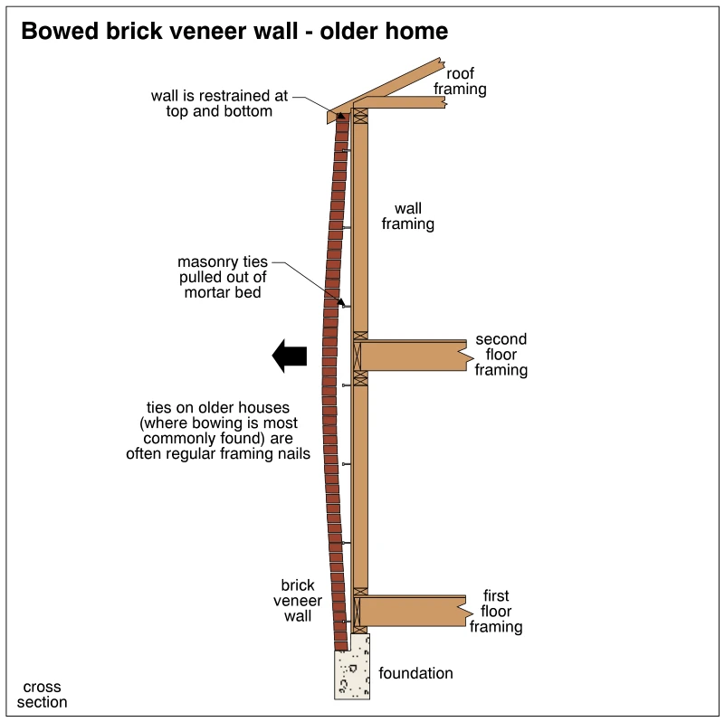
1764Bowed brick veneer wall - older home
· p. 315
The cross section depicts an older home's brick veneer bowing outward away from the wood-framed wall. The veneer remains restrained at the top and bottom, with its greatest outward displacement near the second-floor level. Masonry ties are shown pulled out of the mortar bed, and an annotation notes that ties in older houses are often regular framing nails. Roof framing, first- and second-floor framing, and the supporting foundation establish the veneer’s relationship to the house structure. A large outward-pointing arrow emphasizes the direction of bowing.
 1765
1765Brick veneer wall - masonry tie detail
· p. 315
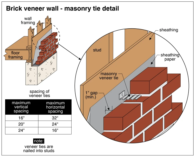
The illustration shows a brick veneer wall outside a wood-framed wall, with an enlarged detail of a masonry veneer tie. Sheathing and sheathing paper separate the studs from an air space labeled as a minimum 1-inch gap behind the brick. A bent, corrugated metal tie extends from the framing side into a horizontal mortar joint in the veneer, and a note specifies that veneer ties are nailed into studs. A spacing table pairs maximum vertical and horizontal tie spacings of 16 and 32 inches, 20 and 24 inches, and 24 and 16 inches, respectively. The smaller overview shows the veneer and framed wall above a foundation beside floor framing.
 1766
1766Lateral support for masonry walls
· p. 316
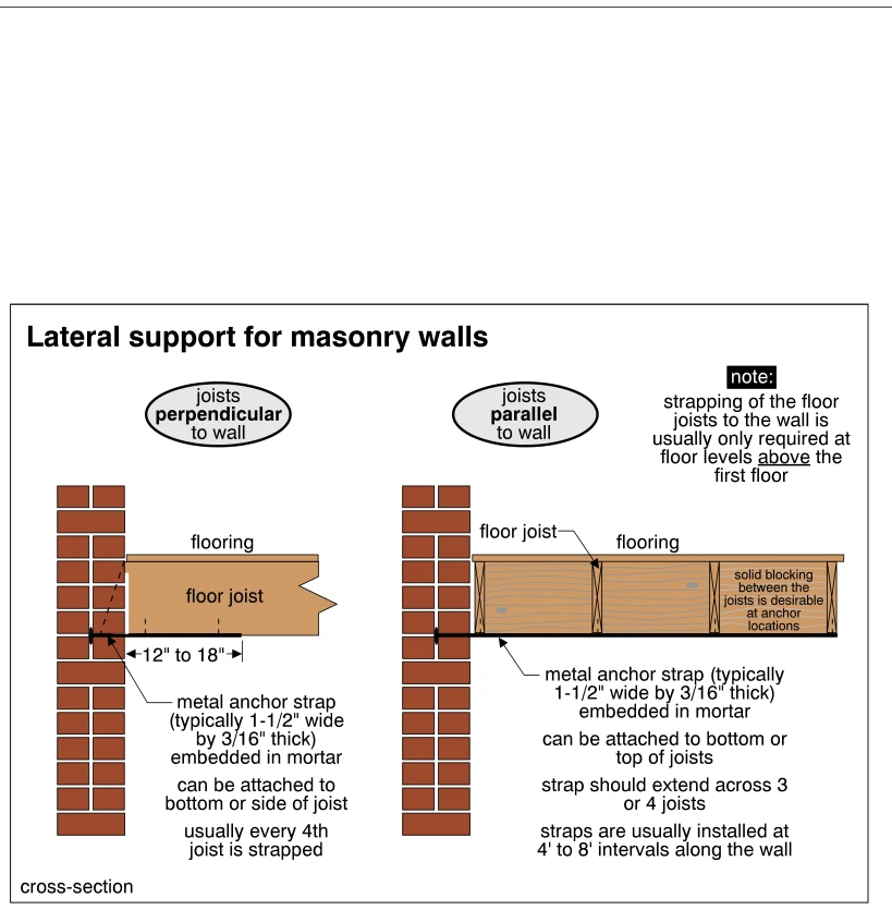
Two cross-sections illustrate lateral support of masonry walls using metal anchor straps connecting the walls to wood floor framing. For joists perpendicular to the wall, a strap embedded in mortar attaches to the bottom or side of a joist, with a 12- to 18-inch dimension indicated and usually every fourth joist strapped. For joists parallel to the wall, the strap attaches to the bottom or top of the joists and extends across three or four joists, with solid blocking identified as desirable at anchor locations. The parallel-joist detail specifies typical strap spacing of 4 to 8 feet along the wall. Both details identify typical straps as 1-1/2 inches wide by 3/16 inch thick, and a note states that strapping is usually required only at floor levels above the first floor.
 1767
1767Bowing of masonry walls
· p. 316
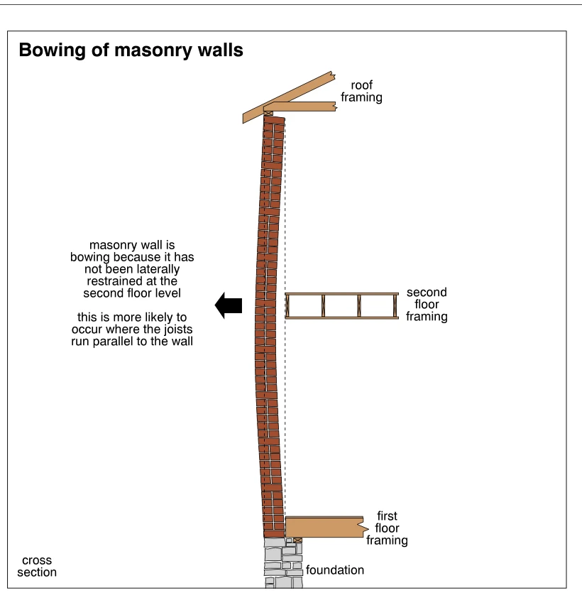
The cross section shows a brick masonry wall extending from a masonry foundation to roof framing, with first- and second-floor framing on the interior side. The wall bows outward between its base and roof, away from a dashed vertical reference line. An outward-pointing arrow highlights the displacement near the second-floor level. The annotations attribute the bowing to a lack of lateral restraint at the second floor and note that this is more likely where floor joists run parallel to the wall.
 1768
1768Stucco - three coat process
· p. 316
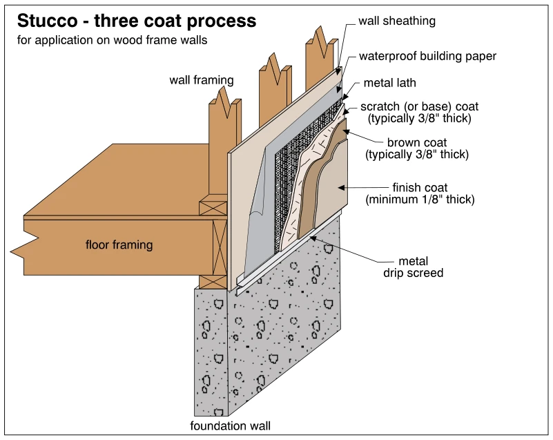
The cutaway illustrates a three-coat stucco assembly applied over a wood-framed exterior wall above a foundation wall. Wall sheathing is covered by waterproof building paper and metal lath, which supports the stucco coats. The scratch or base coat and brown coat are each labeled as typically 3/8 inch thick, while the finish coat is labeled as a minimum of 1/8 inch thick. A metal drip screed terminates the stucco assembly at its lower edge near the foundation. The adjacent floor framing and wall framing show how the cladding relates to the supporting structure.
 1769
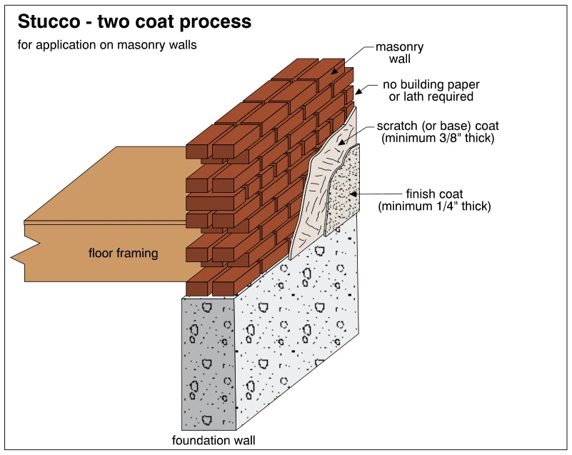
1769Stucco - two coat process
· p. 316
The illustration shows a two-coat stucco application over a brick masonry wall supported by a foundation wall, with floor framing on the interior side. Peeled-back layers reveal a scratch or base coat applied directly to the masonry and a finish coat over it. The base coat is labeled as a minimum of 3/8 inch thick, and the finish coat as a minimum of 1/4 inch thick. The drawing explicitly notes that building paper and lath are not required for this masonry-wall application.
Exterior Cladding ·Stuccop. 317
 1770
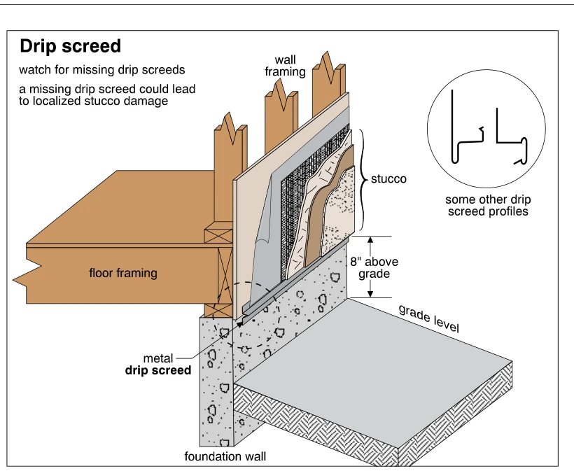
1770Drip screed
· p. 317
The illustration shows a cutaway of a stucco-clad framed wall at its junction with floor framing and a foundation wall. The exposed wall layers include sheathing, backing layers, mesh reinforcement, and stucco, with a metal drip screed terminating the bottom of the cladding. The stucco termination is dimensioned 8 inches above grade. An inset shows alternative drip screed profiles. Notes advise watching for missing drip screeds and warn that their absence could lead to localized stucco damage.
 1771
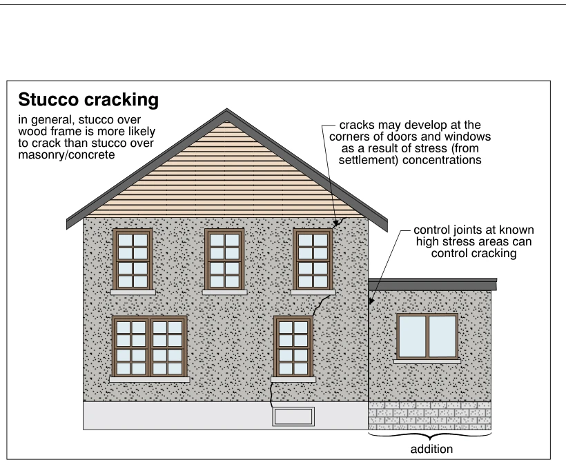
1771Stucco cracking
· p. 317
The illustration shows a two-story stucco-clad house with a gabled roof and a single-story addition. Cracks extend from several window corners in the main wall, illustrating stress concentrations associated with settlement. A vertical control joint is indicated at the junction between the main house and the addition as a means of controlling cracking in a high-stress area. An annotation notes that stucco over wood framing is generally more likely to crack than stucco over masonry or concrete.
 1772
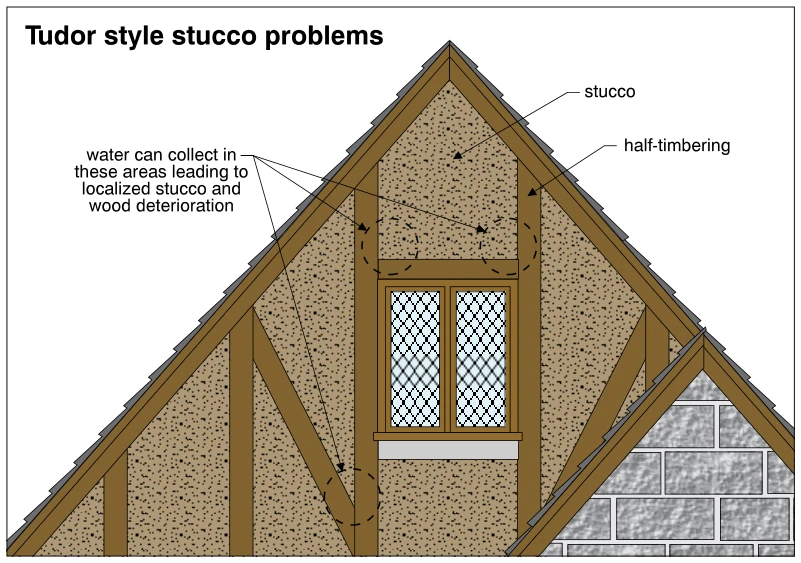
1772Tudor style stucco problems
· p. 317
The illustration shows a Tudor-style gable wall with stucco panels separated by vertical, horizontal, and diagonal wood half-timbering. A two-part window sits within the central timber-framed area, and part of a smaller masonry-faced gable overlaps the wall at the lower right. Arrows and dashed circles identify water-collection locations at stucco-to-wood interfaces above the window and at a lower diagonal-to-vertical timber junction. The annotation warns that water collecting at these locations can cause localized deterioration of both stucco and wood.
 1773
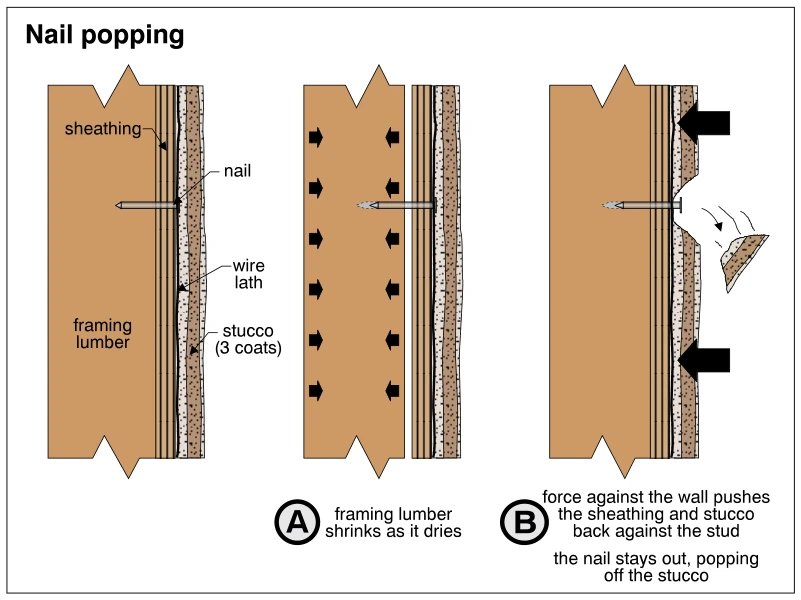
1773Nail popping
· p. 317
Three wall cross-sections illustrate nail popping in a three-coat stucco assembly over wire lath and sheathing attached to framing lumber. The first section identifies the wall layers and a nail penetrating the framing. Stage A shows the framing lumber shrinking as it dries, leaving a gap between the stud and sheathing. Stage B shows force pushing the sheathing and stucco back against the stud while the nail remains projecting. The nail head breaks off a localized piece of stucco, shown falling away from the wall.
 1774
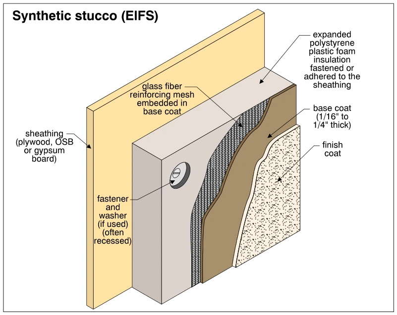
1774Synthetic stucco (EIFS)
· p. 317
The illustration shows a cutaway of a synthetic stucco exterior insulation and finish system (EIFS). Expanded polystyrene foam insulation is fastened or adhered to wall sheathing, identified as plywood, OSB, or gypsum board. A fastener and washer are shown recessed into the foam insulation. Glass fiber reinforcing mesh is embedded in a base coat labeled 1/16 to 1/4 inch thick, with a textured finish coat forming the exterior surface. The peeled-back layers illustrate the assembly sequence rather than damage or a defect.
 1775
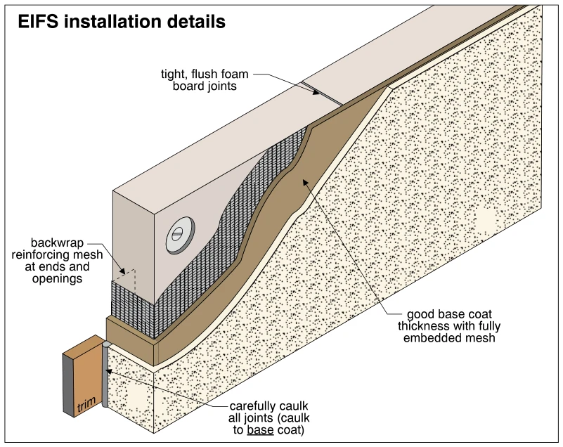
1775EIFS installation details
· p. 317
The illustration shows a cutaway of an exterior insulation and finish system (EIFS), exposing foam insulation board, reinforcing mesh, base coat, and a textured exterior finish. Foam board joints are shown tight and flush, and a circular fastening washer is visible on the board face. Reinforcing mesh wraps around the exposed board end, with a callout requiring backwrapping at ends and openings. The base coat is shown thick enough to fully embed the mesh. At the adjacent trim, the drawing calls for carefully caulking all joints to the base coat.
 1776
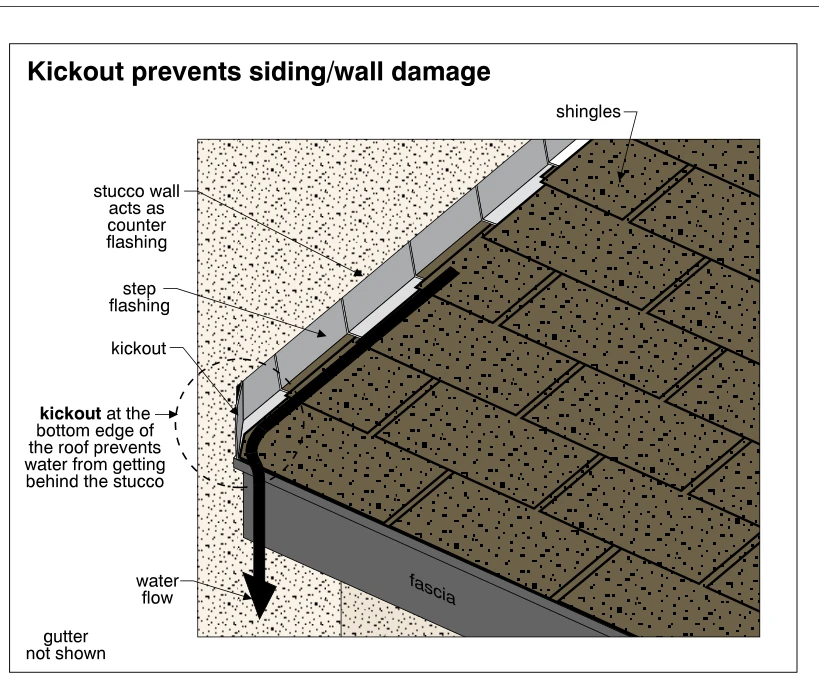
1776Kickout prevents siding/wall damage
· p. 318
The illustration shows a shingled roof meeting a stucco sidewall, with step flashing along the sloped roof-to-wall intersection. The stucco overlaps the upright flashing legs and is labeled as acting as counter flashing. A kickout at the bottom of the flashing diverts runoff outward at the roof edge, preventing water from getting behind the stucco. A heavy arrow traces water flow down the intersection and away from the wall beside the fascia; the gutter is explicitly not shown.
 1776.2
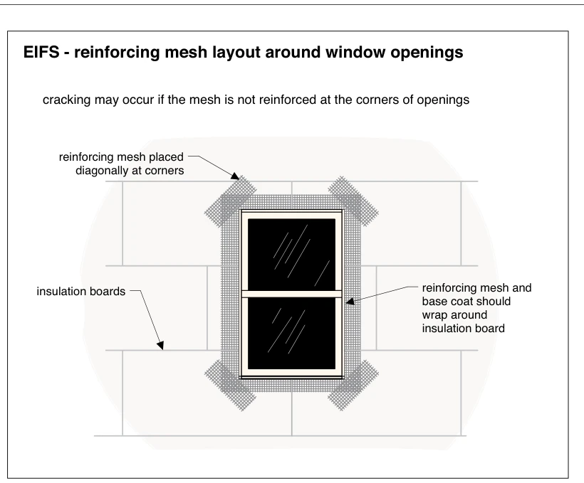
EIFS - reinforcing mesh layout around window openings
· p. 318
The illustration shows a window opening in an exterior insulation and finish system (EIFS) wall with insulation boards laid around it. Reinforcing mesh extends around the window perimeter, with additional diagonal mesh patches at all four corners. A callout specifies that the reinforcing mesh and base coat should wrap around the insulation board at the opening. The drawing warns that cracking may occur if the corners of openings are not reinforced.
 1776.4
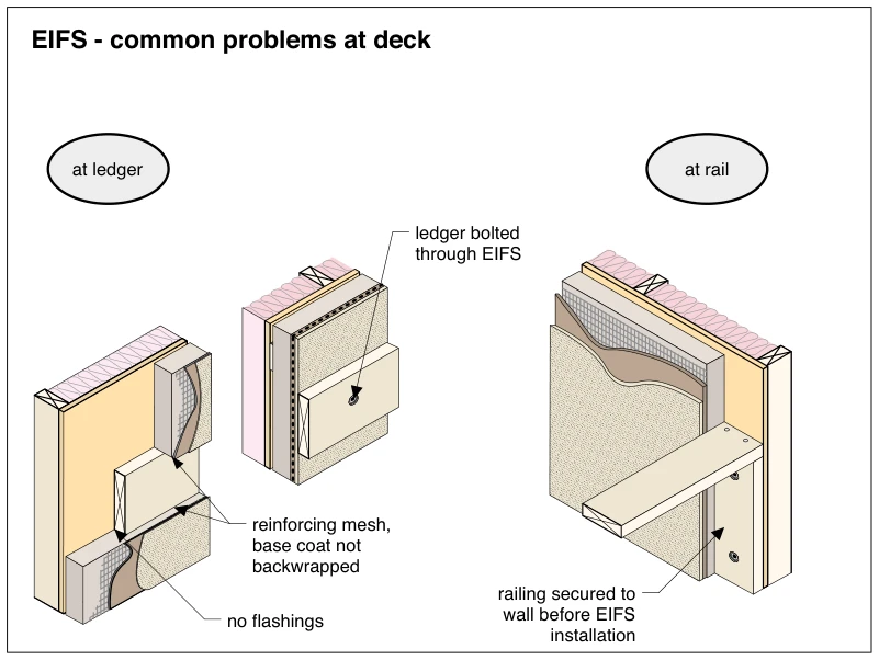
EIFS - common problems at deck
· p. 318
The illustration shows cutaway views of common defects where a deck ledger and railing meet an exterior insulation and finish system (EIFS) wall. At the ledger, the reinforcing mesh and base coat are not backwrapped at the EIFS terminations, and flashings are missing. A separate view shows a ledger bolted through the EIFS cladding. At the rail connection, the railing is secured to the wall before the EIFS is installed, with the cladding terminating around the attachment.
 1776.6
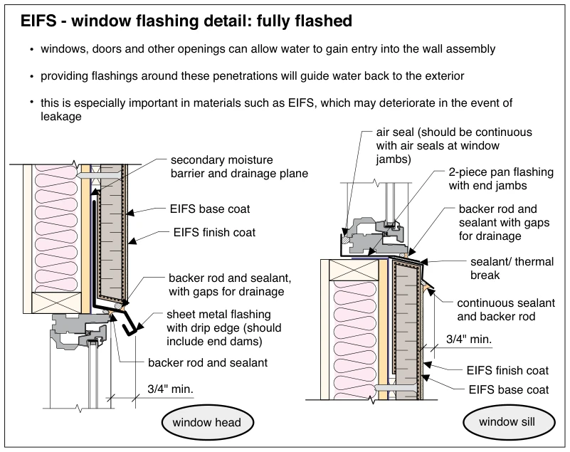
EIFS - window flashing detail: fully flashed
· p. 318
Two sectional details show fully flashed window head and sill intersections with an EIFS-clad wall. At the head, a secondary moisture barrier and drainage plane direct water to sheet metal flashing with a projecting drip edge; the annotation specifies end dams. At the sill, a two-piece pan flashing is shown with an interior air seal that should continue to the window jambs. Backer rod and sealant joints include designated drainage gaps, while other joints are identified as continuous seals or a sealant/thermal break. Both details mark a 3/4-inch minimum dimension at the projecting flashing, and the introductory notes explain that flashing routes leakage back outside to protect the wall assembly.
 1776.8
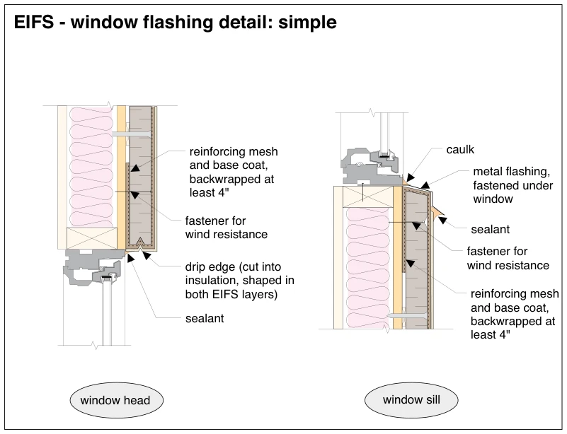
EIFS - window flashing detail: simple
· p. 318
Two sectional details show EIFS terminations at a window head and window sill in an insulated framed wall. Both details specify reinforcing mesh and base coat backwrapped at least 4 inches and fasteners for wind resistance. At the head, a drip edge is cut into the insulation and shaped in both EIFS layers, with sealant at the window junction. At the sill, metal flashing fastened under the window slopes outward over the EIFS and turns down at its outer edge. Caulk is shown at the window-to-flashing junction, with sealant beneath the flashing edge.
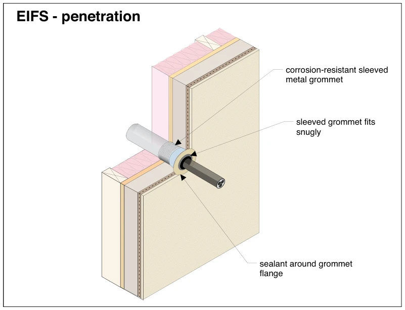 1776.10
EIFS - penetration
· p. 318
The illustration shows a cutaway of an EIFS-clad wall with a wire passing through its exterior face. A corrosion-resistant sleeved metal grommet lines the penetration, with its flange seated against the exterior finish. The grommet fits snugly around the wire, and sealant surrounds the grommet flange. This depicts a properly detailed wire penetration through EIFS to limit water entry.
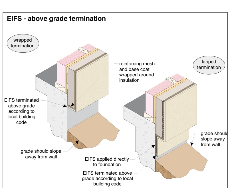 1776.12
EIFS - above grade termination
· p. 319
Two cutaway wall-to-foundation details illustrate wrapped and lapped above-grade terminations of exterior insulation and finish systems (EIFS). In the wrapped detail, reinforcing mesh and base coat wrap around the bottom edge of the insulation, leaving the foundation exposed below. In the lapped detail, the upper EIFS assembly overlaps a thinner EIFS application directly on the foundation. Both details specify termination above grade according to local building code and show the adjacent grade sloping away from the wall.
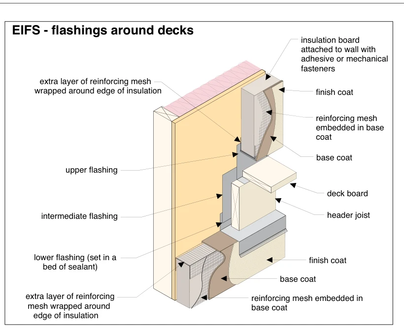 1776.14
EIFS - flashings around decks
· p. 319
An exploded cutaway shows flashing at the intersection of a deck and an exterior insulation and finish system (EIFS) wall. A deck board rests on a header joist, with upper, intermediate, and lower flashings arranged behind and around the deck-to-wall connection. The lower flashing is specified to be set in a bed of sealant. Cutaway EIFS sections above and below the deck expose the insulation board, reinforcing mesh embedded in the base coat, and finish coat. Extra reinforcing mesh wraps the insulation edges at both terminations.
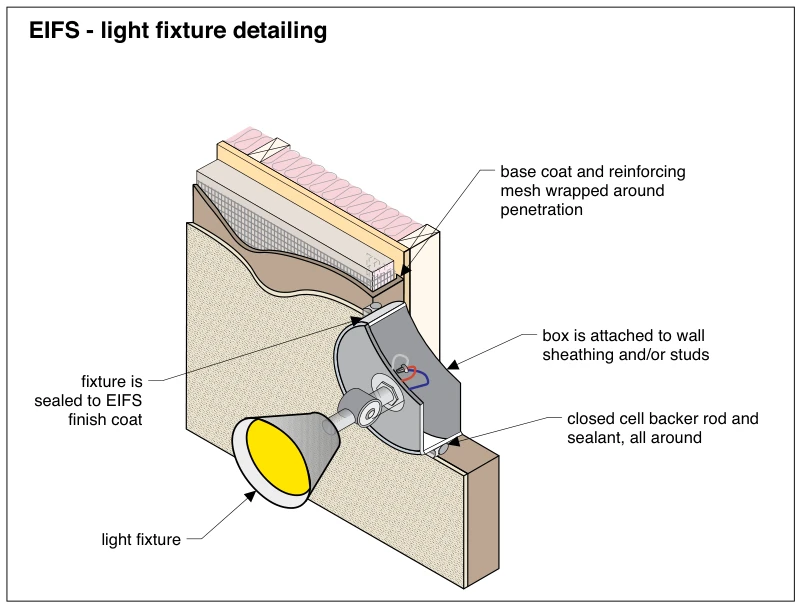 1776.16
EIFS - light fixture detailing
· p. 319
A cutaway exterior wall shows a light fixture installed through an exterior insulation and finish system (EIFS). The exposed layers illustrate the finish coat, base coat and reinforcing mesh, insulation, and wall backing. The base coat and reinforcing mesh wrap around the fixture penetration, and the electrical box is attached to the wall sheathing and/or studs. Closed cell backer rod and sealant surround the penetration, while the fixture is sealed to the EIFS finish coat. The illustration depicts proper attachment and sealing of a light fixture at an EIFS wall.
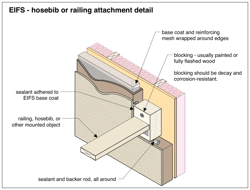 1776.18
EIFS - hosebib or railing attachment detail
· p. 319
The cutaway shows an exterior insulation and finish system (EIFS) wall with a projecting mounted object secured at a wood blocking detail. The blocking occupies an opening in the EIFS, with sealant and backer rod specified around its perimeter. The base coat and reinforcing mesh wrap around the exposed EIFS edges, and the sealant adheres to the base coat. Annotations specify painted or fully flashed wood blocking and call for decay and corrosion resistance.
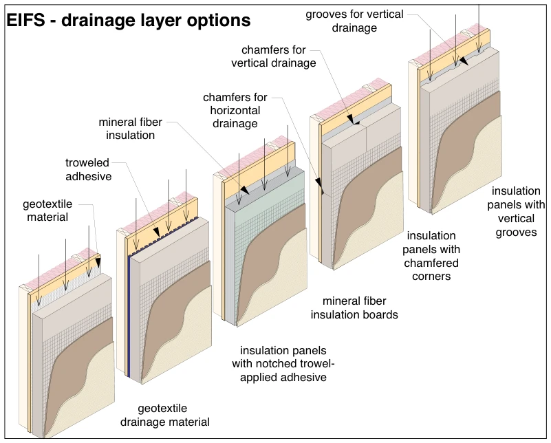 1776.20
EIFS - drainage layer options
· p. 319
Five cutaway wall assemblies illustrate drainage layer options behind exterior insulation and finish systems (EIFS). The options shown are geotextile drainage material, insulation panels with notched trowel-applied adhesive, mineral fiber insulation boards, panels with chamfered corners, and panels with vertical grooves. Arrows indicate drainage paths behind the insulation, with callouts identifying horizontal and vertical drainage at chamfers and vertical drainage through grooves. Each assembly shows the backing wall, insulation, reinforcing mesh, and partially cut-away exterior coating layers. The illustration presents alternative drainage configurations without identifying a defective installation.
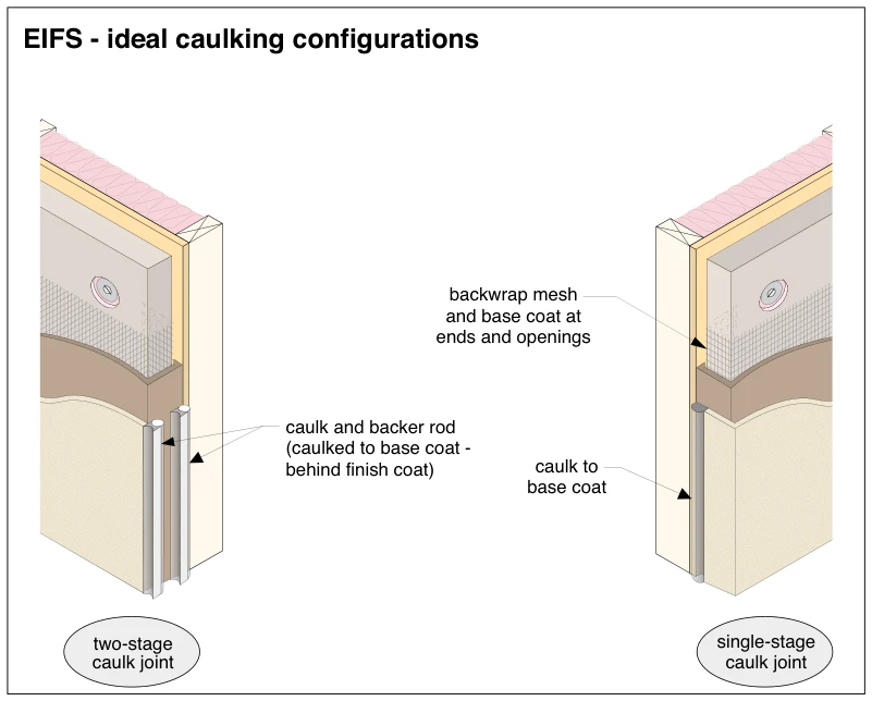 1776.22
EIFS - ideal caulking configurations
· p. 319
The illustration shows cutaway EIFS wall terminations with a two-stage caulk joint on the left and a single-stage caulk joint on the right. The cutaways expose insulation board, reinforcing mesh, base coat, and finish coat. Mesh and base coat backwrap the EIFS at ends and openings. The caulking bonds to the base coat behind the finish coat, with caulk and backer rod identified in the two-stage detail. Both details are presented as ideal caulking configurations.
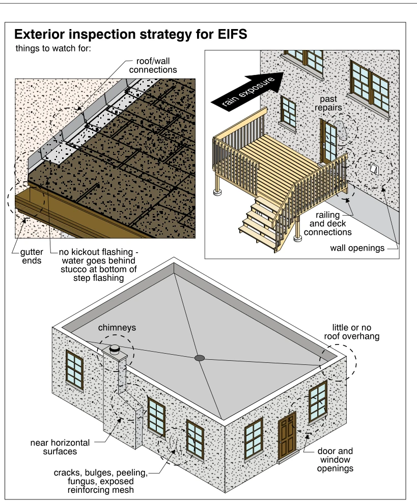 1777
1777Exterior inspection strategy for EIFS
· p. 320
The illustration identifies inspection priorities for exterior insulation and finish systems (EIFS) using a roof-to-wall detail, a deck connection view, and an overview of a clad house. The roof detail shows step flashing and a gutter end, with missing kickout flashing allowing water behind the stucco at the bottom of the flashing. The deck view highlights rain exposure, past repairs, railing and deck attachments, and wall openings. The house overview marks chimneys, near-horizontal surfaces, limited roof overhang, and door and window openings as areas to examine. It also calls attention to cracks, bulges, peeling, fungus, and exposed reinforcing mesh in the cladding.
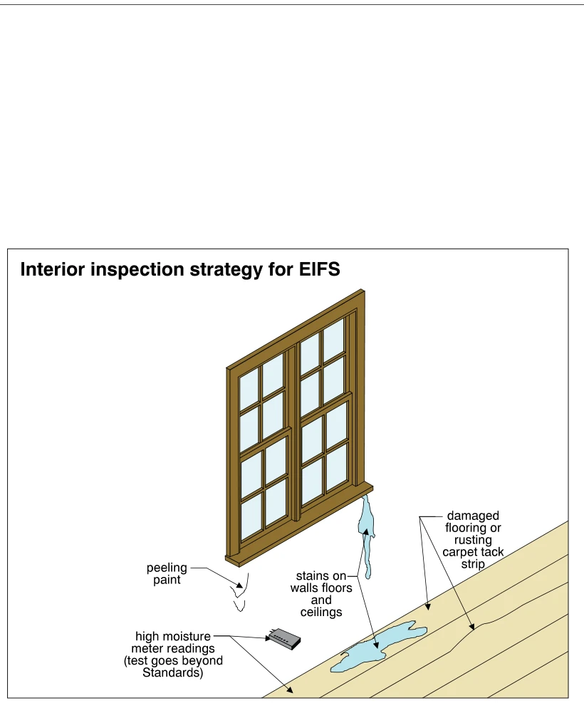 1778
1778Interior inspection strategy for EIFS
· p. 320
The illustration shows an interior wall with a paired window and adjacent plank flooring, identifying signs to look for when inspecting a home with EIFS cladding. Peeling paint and staining are shown beneath the window, with additional staining and damage on the floor. A moisture meter represents testing for elevated moisture levels; the annotation notes that this test goes beyond Standards. Another callout identifies damaged flooring or rusting carpet tack strip as possible interior evidence of moisture problems.
Exterior Cladding ·Woodp. 321
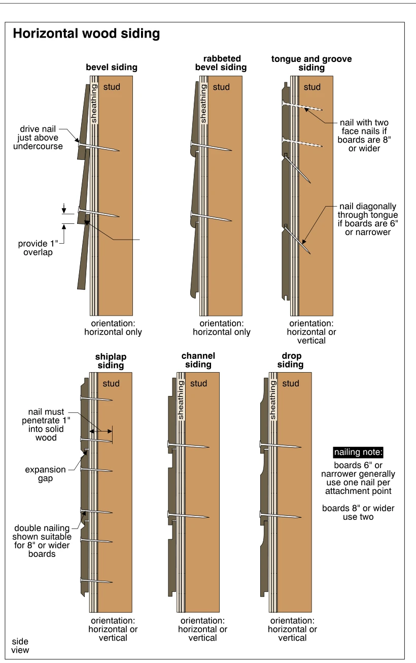 1779
1779Horizontal wood siding
· p. 321
Six side-view wall sections illustrate bevel, rabbeted bevel, tongue-and-groove, shiplap, channel, and drop wood siding attached through sheathing to studs. Bevel siding is shown with a 1-inch overlap and nails driven just above the undercourse; both bevel profiles are identified for horizontal installation only. Tongue-and-groove siding shows two face nails for boards 8 inches or wider and diagonal nailing through the tongue for boards 6 inches or narrower. The shiplap detail identifies an expansion gap, 1-inch nail penetration into solid wood, and double nailing for wider boards. Tongue-and-groove, shiplap, channel, and drop siding are identified as suitable for horizontal or vertical orientation, with a general note relating nail count to board width.
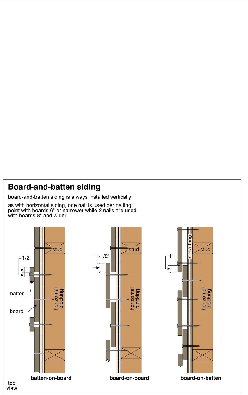 1780
1780Board-and-batten siding
· p. 321
Three top-view details show vertical wood siding arrangements labeled batten-on-board, board-on-board, and board-on-batten. Narrow battens cover joints between wide boards in the first arrangement, wide boards overlap in the second, and wide outer boards overlap underlying battens in the third. Nails secure the siding over sheathing to horizontal blocking between studs. Dimension callouts indicate overlaps of 1/2 inch, 1-1/2 inches, and 1 inch for the respective arrangements. The notes specify vertical installation and one nail per nailing point for boards 6 inches or narrower, versus two nails for boards 8 inches and wider.
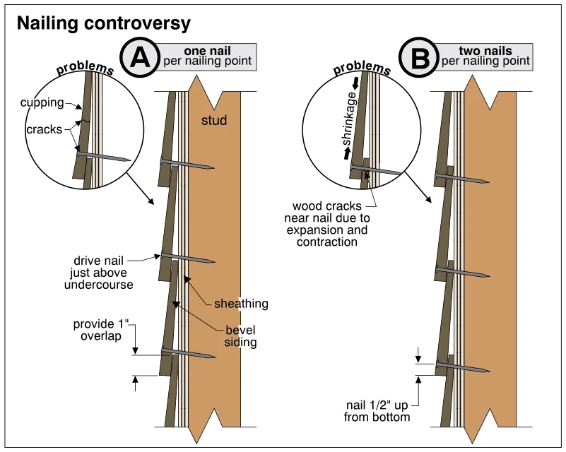 1781
1781Nailing controversy
· p. 321
The illustration compares two fastening arrangements for overlapping wood bevel siding installed over sheathing and studs. Detail A places nails just above the undercourse, with a specified 1-inch overlap, so each board has one nail per nailing point; its enlarged inset identifies cupping and cracks as potential problems. Detail B places nails 1/2 inch above the bottom edge and through the overlapping boards, resulting in two nails per nailing point. Its inset shows shrinkage and cracking near a nail due to expansion and contraction. The drawing presents the competing problems of the two methods rather than identifying one as unconditionally correct.
 1782
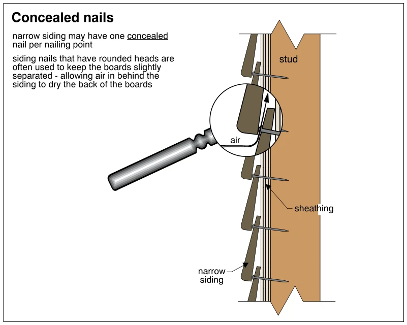
1782Concealed nails
· p. 321
The illustration shows a vertical section through narrow, overlapping wood siding installed over sheathing and a wall stud. Each siding board is secured with a nail through its upper portion, concealed by the overlapping board above. A magnified detail shows how rounded nail heads keep adjacent boards slightly separated, with an arrow indicating air entering behind the siding. The annotations explain that this air helps dry the backs of the boards and that narrow siding may have one concealed nail per nailing point.
 1783
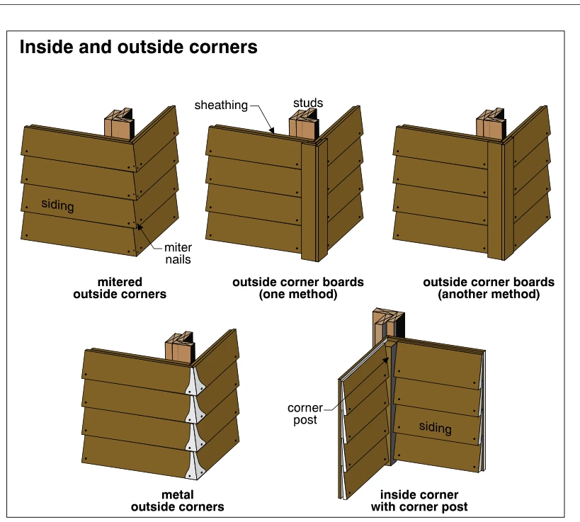
1783Inside and outside corners
· p. 322
The illustration shows five ways to finish corners in horizontal wood lap siding over sheathing and stud framing. One outside corner uses mitered siding ends secured with miter nails, while two others use different arrangements of vertical outside corner boards. A fourth outside corner uses individual metal corner pieces at each siding course. The inside corner detail shows siding on both walls terminating against a vertical corner post. These are alternative construction details; no defects are indicated.
 1784
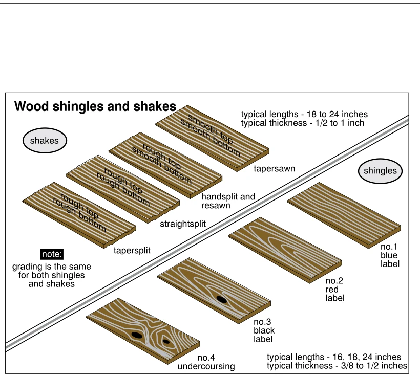
1784Wood shingles and shakes
· p. 322
The illustration presents individual wood shakes and shingles, separated diagonally into two groups. Shake types include tapersawn with smooth top and bottom, handsplit and resawn with a rough top and smooth bottom, and straightsplit and tapersplit with rough top and bottom surfaces. Shingles are illustrated as No. 1 blue label, No. 2 red label, No. 3 black label, and No. 4 undercoursing, with knots visible in the latter two examples. Typical shake dimensions are 18 to 24 inches long and 1/2 to 1 inch thick; typical shingle dimensions are 16, 18, or 24 inches long and 3/8 to 1/2 inches thick. A note states that grading is the same for both shingles and shakes.
 1785
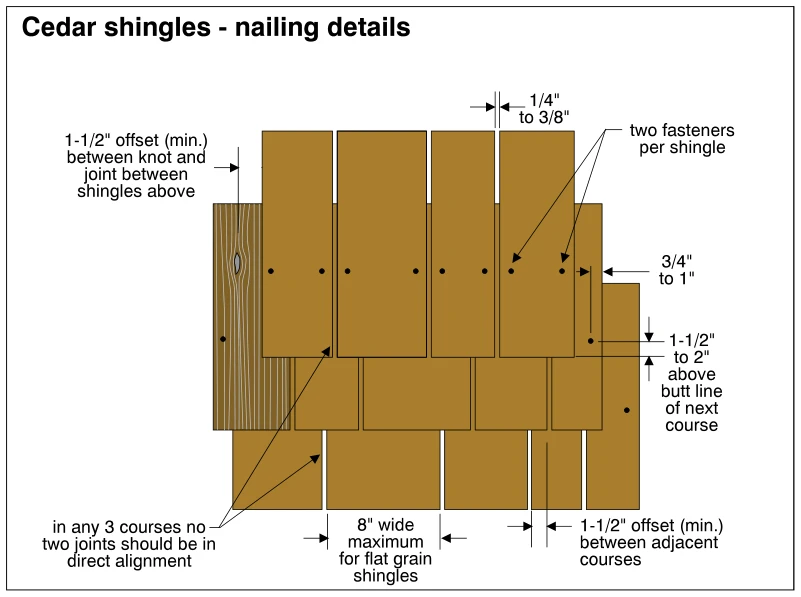
1785Cedar shingles - nailing details
· p. 322
The illustration shows overlapping courses of cedar shingle siding with recommended fastener locations and staggered joints. Each shingle receives two fasteners, located 3/4 to 1 inch from its edges and 1-1/2 to 2 inches above the butt line of the next course. Side joints have a 1/4- to 3/8-inch gap, and joints in adjacent courses are offset at least 1-1/2 inches; no two joints in any three courses should align directly. A knot in a lower shingle is shown with a minimum 1-1/2-inch offset from the joint between shingles above. Flat-grain shingles are limited to a maximum width of 8 inches.
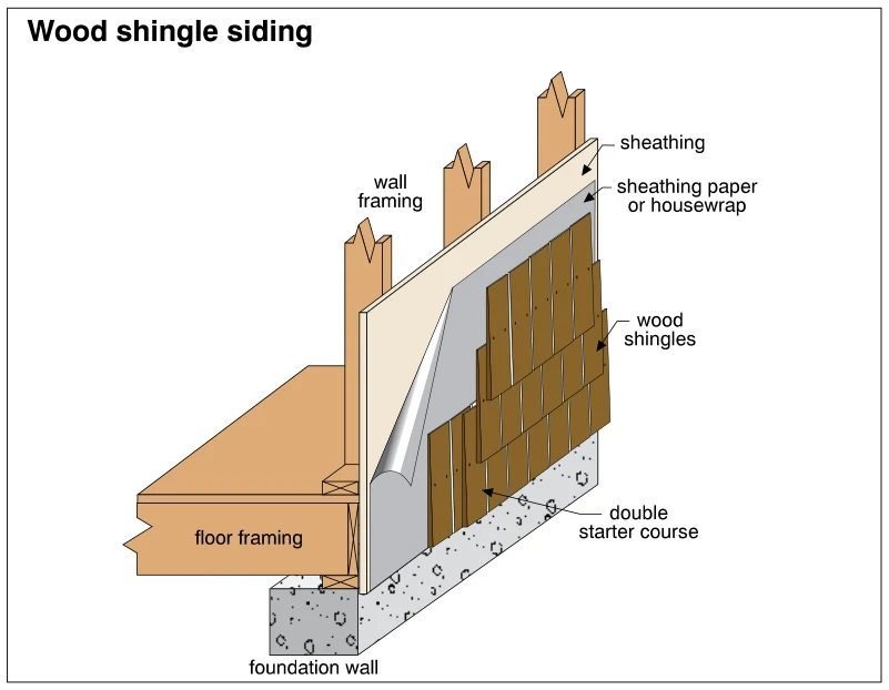 1786
1786Wood shingle siding
· p. 322
The illustration shows a cutaway exterior wall clad with wood shingles above a foundation wall. Wall framing supports sheathing, which is covered by sheathing paper or housewrap beneath the shingles. The shingles are installed in overlapping courses with staggered vertical joints and a double starter course at the bottom. A peeled-back portion of the weather barrier reveals the sheathing, and the cutaway also shows the adjacent floor framing. No defects are depicted.
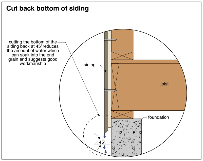 1787
1787Cut back bottom of siding
· p. 322
The illustration shows a wall-base cross section with wood siding outside floor framing supported by a concrete foundation. The siding extends below the framing, and its bottom edge is cut back at 45°. Water droplets are shown falling from the outer tip of the beveled edge. The annotation identifies this cut as good workmanship that reduces water absorption into the siding's end grain.
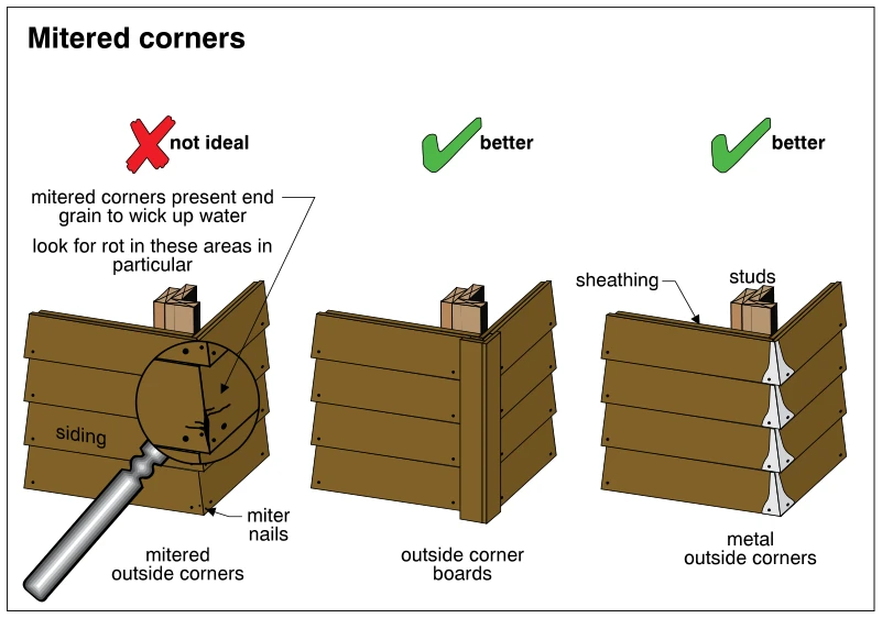 1788
1788Mitered corners
· p. 322
The illustration compares three outside-corner treatments for horizontal wood lap siding. Mitered siding corners are marked “not ideal” because exposed end grain can wick up water; a magnified detail identifies the corner joint and directs inspection for rot. The other two assemblies, marked “better,” use outside corner boards or individual metal outside corners over the siding ends. Sheathing and studs are identified behind the siding.
Plywood, Hardboard and OSBp. 323
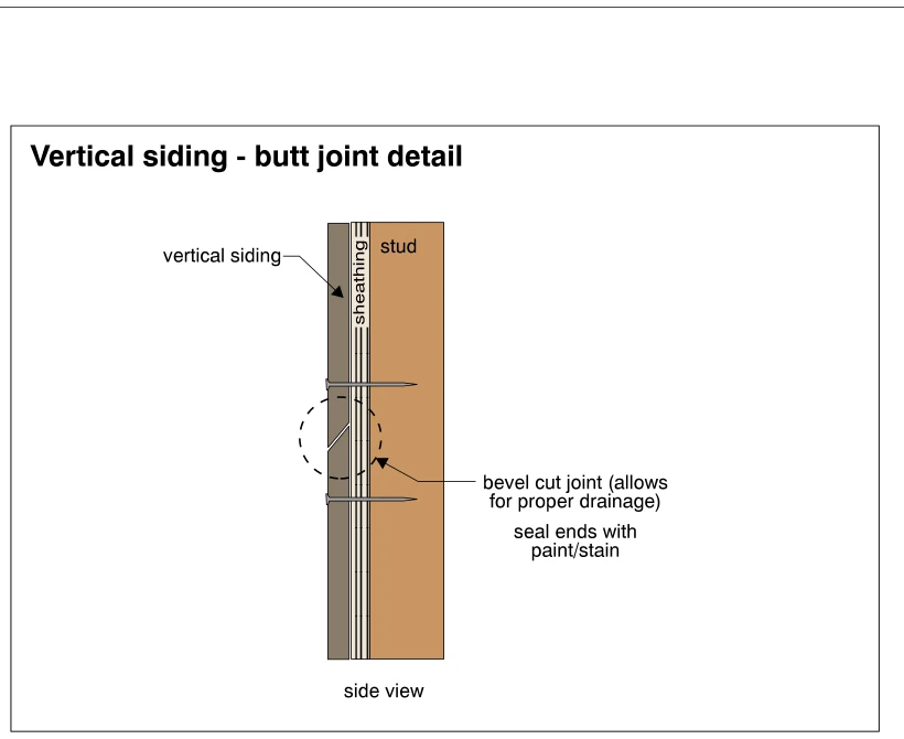 1789
1789Vertical siding - butt joint detail
· p. 323
The illustration shows a side view of a butt joint between two lengths of vertical siding installed over sheathing and a wall stud. Nails above and below the joint pass through the siding and sheathing into the stud. The siding ends meet at a bevel-cut joint that slopes downward toward the exterior to allow drainage. An annotation specifies sealing the ends with paint or stain.
 1790
1790Joints in siding boards
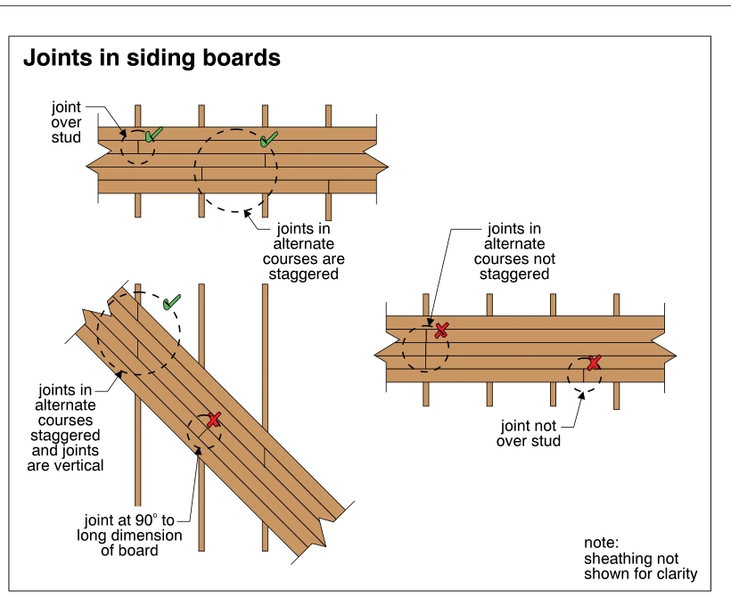
· p. 323
The illustration compares correct and incorrect end-joint placement in horizontal and diagonal wood siding boards over vertical studs. The correct horizontal example places joints over studs and staggers joints in alternate courses. The incorrect horizontal example shows unstaggered joints and a joint located between studs. For diagonal siding, vertical joints with staggered locations are marked correct, while a joint cut at 90° to the board's long dimension is marked incorrect. Sheathing is omitted for clarity.
 1791
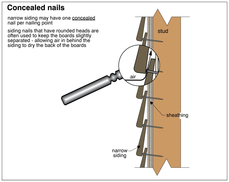
1791Concealed nails
· p. 323
The illustration shows a wall cross-section with overlapping narrow wood siding fastened through sheathing into a stud. Each siding course conceals the nail securing the upper portion of the board below it. A magnified detail shows how rounded nail heads keep the boards slightly separated, allowing air behind the siding to dry the backs of the boards. The annotation indicates that narrow siding may use one concealed nail per nailing point.
 1792
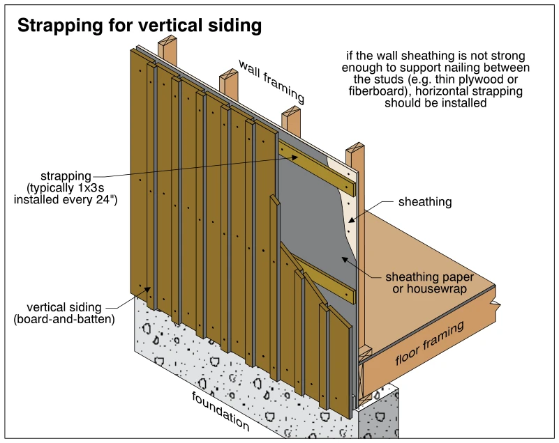
1792Strapping for vertical siding
· p. 323
The cutaway illustrates vertical board-and-batten siding attached to horizontal wood strapping over a framed exterior wall. Exposed portions show wall sheathing and sheathing paper or housewrap behind the strapping. The annotation specifies horizontal strapping where sheathing is not strong enough to support nailing between studs, with typical 1x3 strapping installed every 24 inches. Wall studs, floor framing, and the foundation are shown to establish the assembly's relationship to the building structure.
 1793
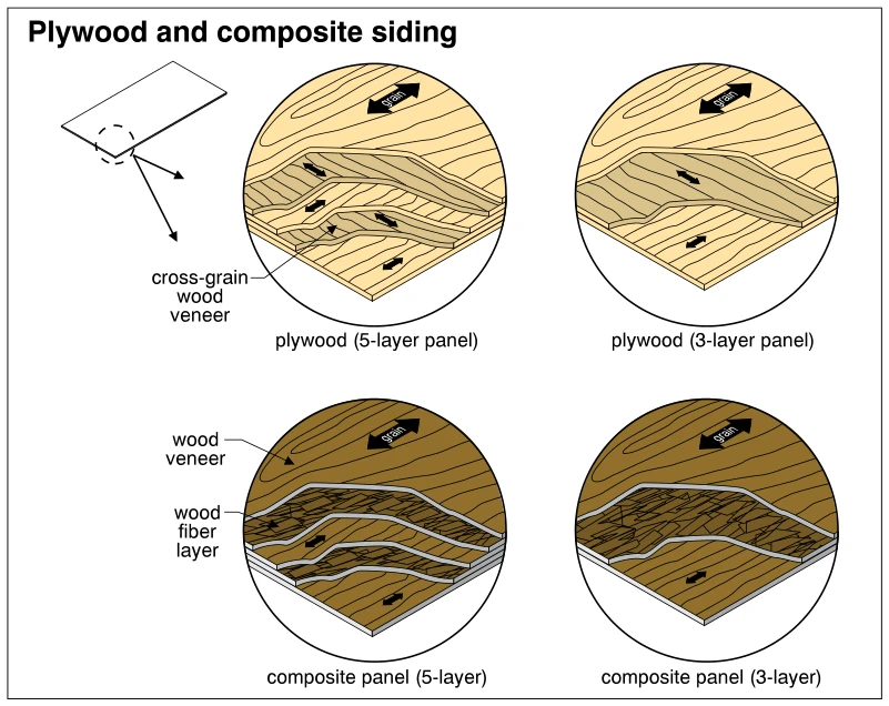
1793Plywood and composite siding
· p. 323
The illustration shows enlarged, peeled-back views of plywood and composite siding panels in three-layer and five-layer configurations. The plywood panels consist of wood veneers with adjacent layers oriented in alternating grain directions, indicated by arrows. The composite panels combine wood veneer with wood fiber layers. A small panel sketch identifies an edge area for enlargement. The drawing explains panel construction rather than depicting installation details or defects.
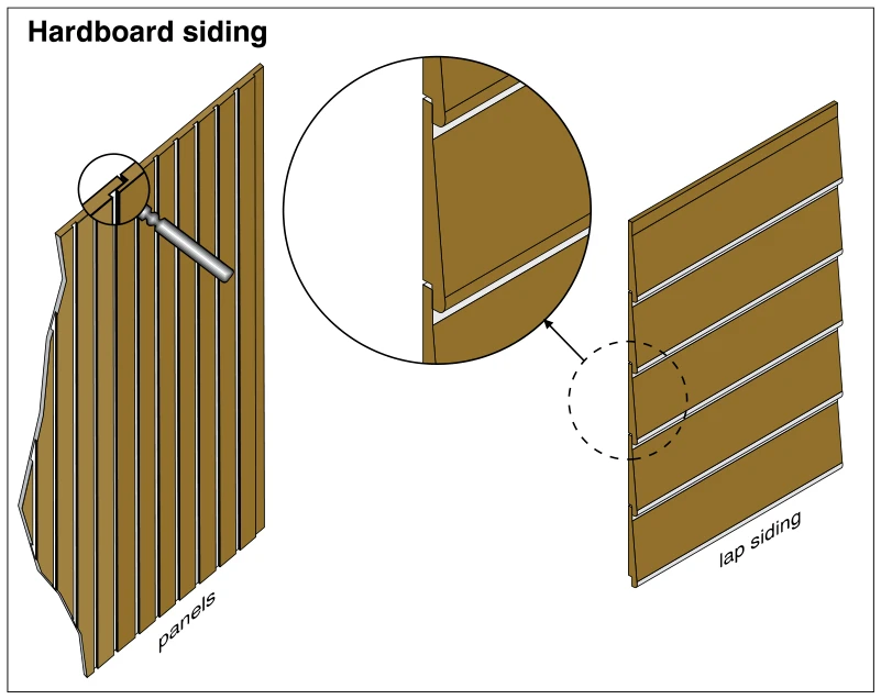 1794
1794Hardboard siding
· p. 323
The illustration shows hardboard siding in two forms: vertically grooved panels on the left and horizontal lap siding on the right. A magnifying-glass graphic highlights the edge and groove profile of the panel siding. A circular enlarged detail shows the overlapping edges of the horizontal siding courses. The drawing illustrates siding profiles rather than an installation defect.
Metal and Vinylp. 324
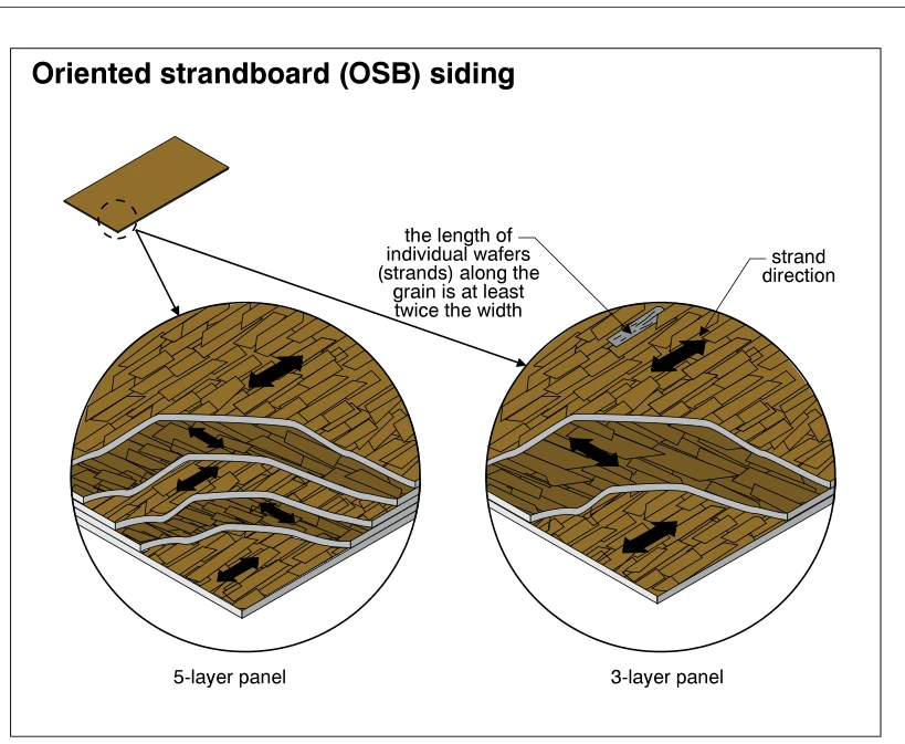 1795
1795Oriented strandboard (OSB) siding
· p. 324
The illustration shows a small siding panel with two enlarged cutaway views of oriented strandboard (OSB) construction. One view depicts a five-layer panel and the other a three-layer panel. The separated layers expose wood strands, with arrows indicating alternating strand directions between adjacent layers. An annotation states that individual wafers or strands are at least twice as long along the grain as they are wide. The drawing explains panel construction rather than showing installation details or defects.
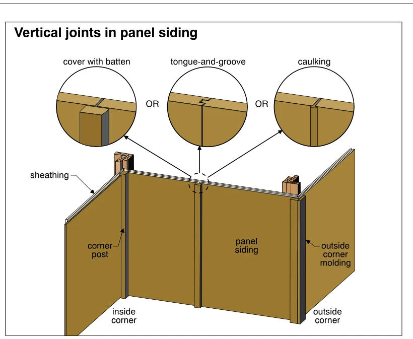 1796
1796Vertical joints in panel siding
· p. 324
The illustration shows panel siding over sheathing on a wall assembly with both inside and outside corners. Three enlarged details show alternative treatments for vertical panel joints: covering the joint with a batten, using tongue-and-groove edges, or caulking the joint. Arrows connect these details to a vertical seam in the main wall. A corner post finishes the inside corner, while outside corner molding covers the exterior corner.
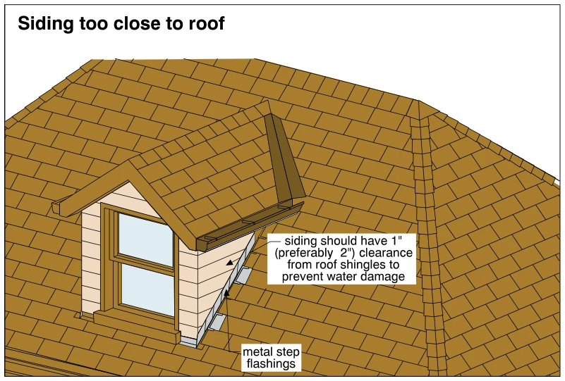 1797
1797Siding too close to roof
· p. 324
The illustration shows a gabled dormer with horizontal siding and a window projecting from a shingled roof. Metal step flashings are exposed along the sloping intersection of the dormer sidewall and the main roof. The siding is identified as too close to the roof shingles. An annotation specifies 1 inch of clearance, preferably 2 inches, between the siding and shingles to prevent water damage.
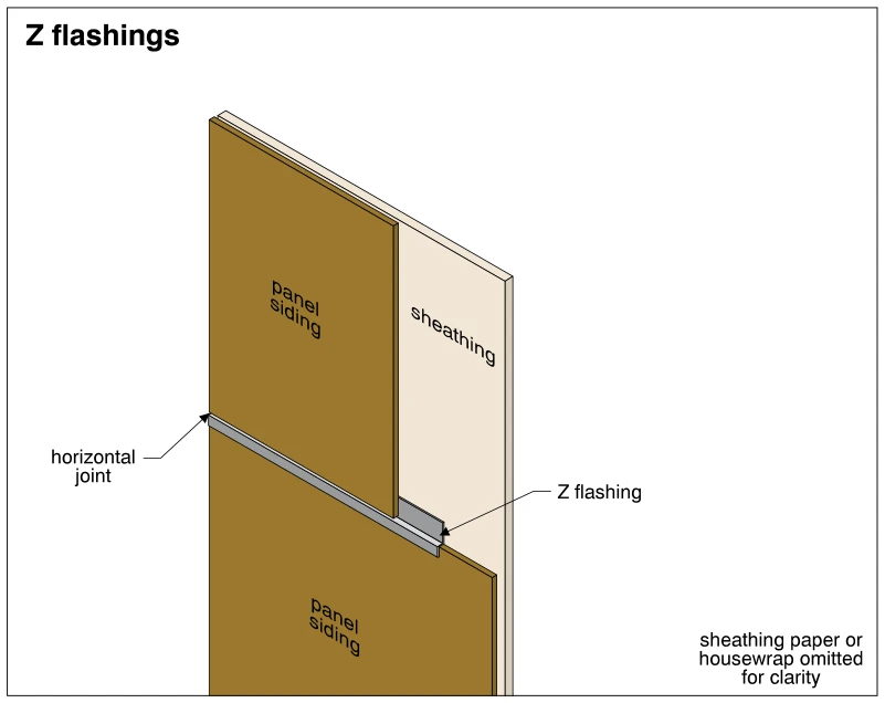 1798
1798Z flashings
· p. 324
The illustration shows a horizontal joint between upper and lower siding panels installed over wall sheathing. Z flashing bridges the joint, with its upper leg behind the upper panel, its middle section covering the top edge of the lower panel, and its outer leg extending down over the lower panel face. This arrangement directs water outward over the siding rather than into the joint. Sheathing paper or housewrap is explicitly omitted for clarity.
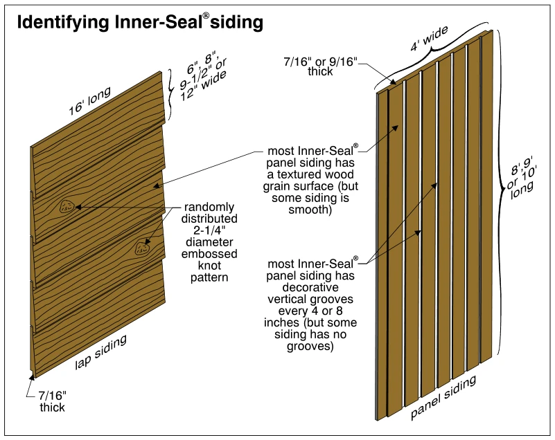 1799
1799Identifying Inner-Seal® siding
· p. 324
The illustration shows identifying features of Inner-Seal® lap siding and panel siding. The lap siding is shown as overlapping horizontal boards with wood-grain texture and randomly distributed embossed knots measuring 2-1/4 inches in diameter. Lap boards are identified as 16 feet long, 7/16 inch thick, and available in four widths. The panel siding is shown with decorative vertical grooves, with annotations noting that most panels have wood-grain texture and grooves every 4 or 8 inches, although smooth and ungrooved versions exist. Panels are identified as 4 feet wide, 8, 9, or 10 feet long, and 7/16 or 9/16 inch thick.
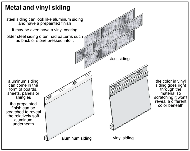 1800
1800Metal and vinyl siding
· p. 324
The illustration presents examples of steel, aluminum, and vinyl exterior siding. The steel siding is shown with a pressed, staggered masonry-like pattern, with notes explaining that steel can have a prepainted finish or vinyl coating. The aluminum and vinyl siding sections show slotted upper fastening flanges and formed lower edges. Annotations distinguish painted aluminum, which can reveal the underlying metal when scratched, from vinyl, whose color extends through the material. No installation defect is depicted.
Other Sidings and Issuesp. 325
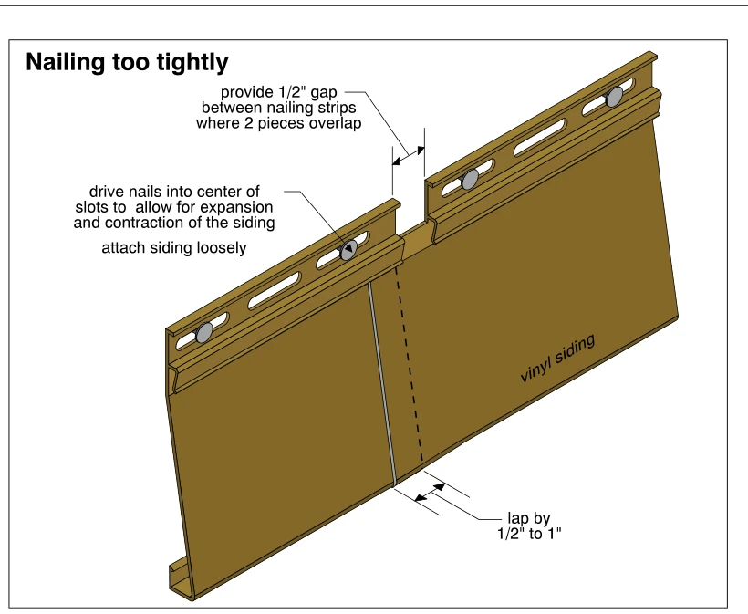 1801
1801Nailing too tightly
· p. 325
The illustration shows two overlapping vinyl siding panels with elongated nail slots in their upper nailing strips. Nails are positioned in the centers of the slots, and the annotations direct installers to attach the siding loosely to permit expansion and contraction. At the joint, the nailing strips are separated by a specified 1/2-inch gap while the panel faces overlap by 1/2 to 1 inch. Although the title identifies nailing too tightly as the concern, the drawing presents installation guidance intended to avoid that condition.
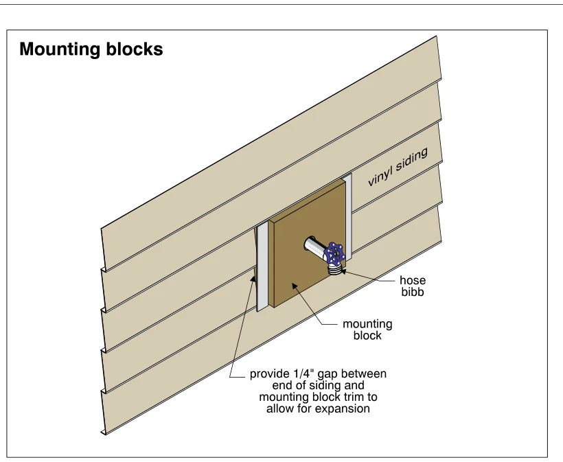 1802
1802Mounting blocks
· p. 325
The illustration shows a hose bibb projecting through a rectangular mounting block within horizontal vinyl siding. Trim borders the mounting block where the siding terminates. A callout specifies a 1/4-inch gap between the siding ends and the mounting block trim to allow for expansion. This depicts proper clearance at an exterior fixture mounting block.
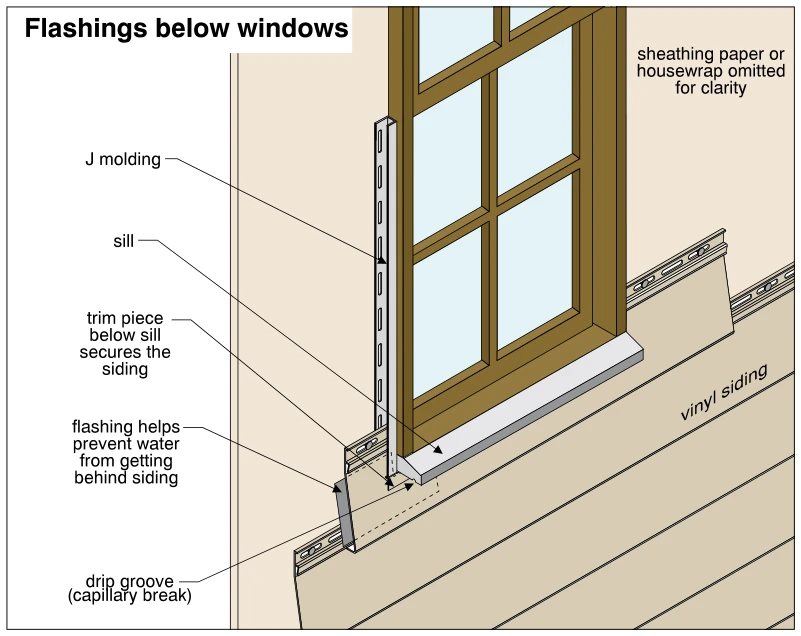 1803
1803Flashings below windows
· p. 325
The illustration shows horizontal vinyl siding installed around the lower portion of a window, with part of the siding cut away to expose the sill flashing and trim. J molding runs vertically beside the window, and a trim piece below the sill secures the siding. Flashing beneath the projecting sill helps prevent water from reaching behind the siding. A drip groove provides a capillary break beneath the sill. Sheathing paper or housewrap is explicitly omitted for clarity, rather than shown as missing construction.
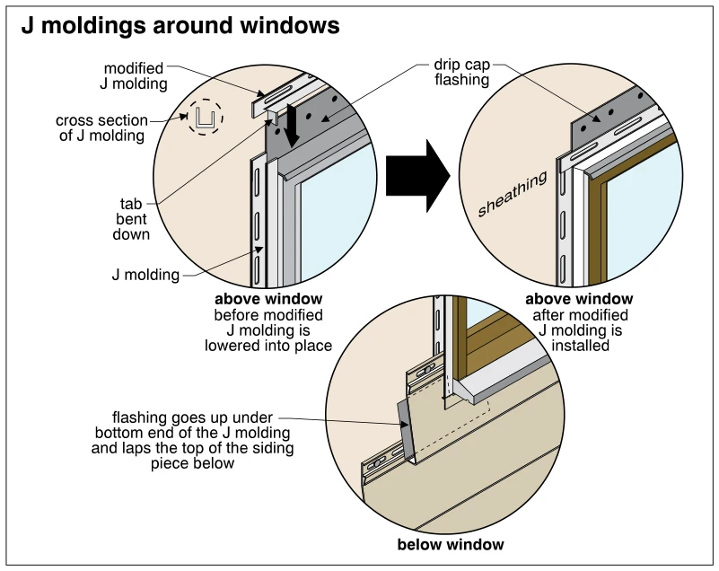 1804
1804J moldings around windows
· p. 325
The illustration shows J-molding and flashing details around a window in metal or vinyl siding. Two upper views show a modified head J molding before and after installation over the window, with an end tab bent down to overlap the side J molding. Drip cap flashing is positioned above the window head, against the sheathing. The lower view shows flashing extending under the bottom end of the side J molding and lapping over the top of the siding piece below to direct water outward.
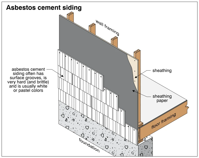 1805
1805Asbestos cement siding
· p. 325
The illustration shows a cutaway exterior wall clad with rectangular asbestos cement siding units in overlapping courses with staggered joints. The siding has vertical surface grooves and visible fasteners near its upper edges. Behind the siding, sheathing paper covers sheathing attached to wood wall framing. The wall meets floor framing above a concrete foundation. An annotation describes asbestos cement siding as very hard and brittle, and usually white or pastel colored; no specific damage is depicted.
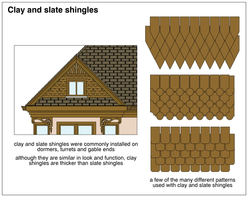 1806
1806Clay and slate shingles
· p. 325
The illustration shows decorative shingle siding on the gable end of an ornamented house, surrounding a small window beneath the rake trim. Three separate examples show overlapping shingle courses with pointed, circular-ended, and rounded rectangular profiles. The annotations identify clay and slate shingles as common claddings for dormers, turrets, and gable ends. They also note that clay shingles are thicker than slate shingles despite their similar appearance and function. No defects or improper installation practices are identified.
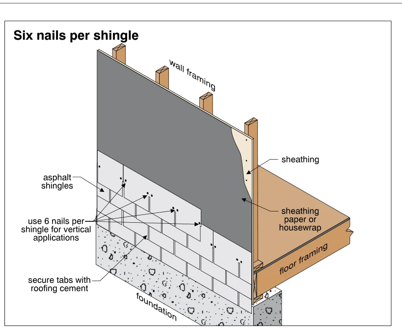 1807
1807Six nails per shingle
· p. 326
The illustration shows asphalt shingles installed as siding on a framed exterior wall above a foundation. A cutaway reveals wall framing, sheathing, and an outer layer of sheathing paper or housewrap behind the shingles. The shingles are arranged in overlapping courses with staggered joints. Arrows indicate six nails per shingle for vertical applications and direct that the shingle tabs be secured with roofing cement. Floor framing is shown at the base of the wall.
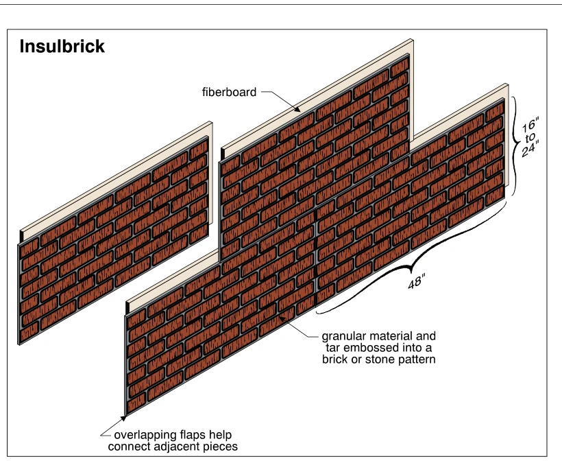 1808
1808Insulbrick
· p. 326
The illustration shows Insulbrick siding panels with fiberboard backing and a granular material and tar facing embossed to resemble brickwork. Separate and adjoining panels illustrate how overlapping flaps connect adjacent pieces. The panels are arranged with staggered vertical joints while maintaining the brick-pattern appearance. Dimension annotations indicate panels 48 inches long and 16 to 24 inches high. No damage or improper installation is depicted.
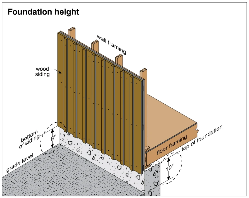 1809
1809Foundation height
· p. 326
The illustration shows a cutaway of a wood-framed exterior wall and floor supported by a concrete foundation. Vertical wood siding covers the wall framing and extends below the floor framing. Dimension arrows indicate 8 inches of clearance between grade level and the bottom of the siding, and 10 inches between grade level and the top of the foundation. The exposed foundation separates the wood construction from the ground.
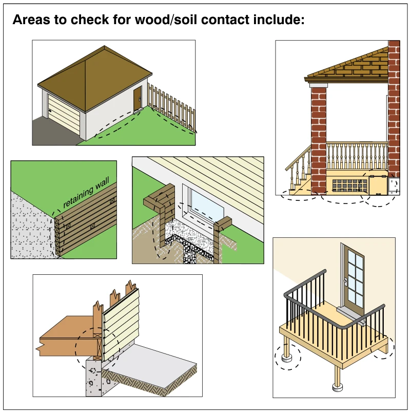 1810
1810Areas to check for wood/soil contact include:
· p. 326
Six vignettes identify locations to inspect for wood/soil contact around a house. Dashed outlines highlight the bases of garage walls and a fence, a timber retaining wall, and a timber-lined basement window well. A porch illustration highlights the stair base, under-porch enclosure, and adjacent wall base. A wall section shows wood siding and framing near an exterior concrete slab, while a deck illustration highlights support posts at ground level. The figure identifies inspection locations rather than explicitly rating each detail as correct or incorrect.
Windows and Doorsp. 327
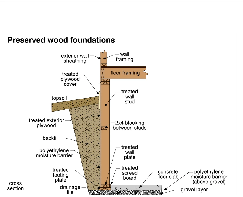 1811
1811Preserved wood foundations
· p. 327
This cross section depicts a preserved wood foundation supporting above-grade wall and floor framing. Treated wall studs with 2x4 blocking support treated exterior plywood, with an exterior polyethylene moisture barrier separating the foundation from backfill. A treated plywood cover protects the upper exterior portion near the topsoil. At the base, a treated wall plate rests on a treated footing plate beside a drainage tile in the gravel layer. The interior concrete floor slab is shown above a polyethylene moisture barrier and gravel, with a treated screed board at its edge.
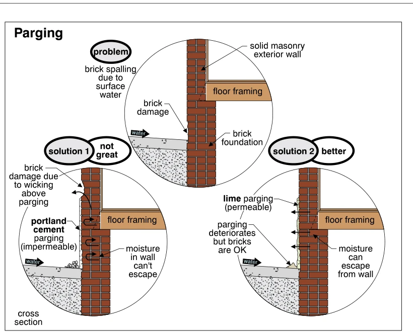 1812
1812Parging
· p. 327
Three cross sections illustrate surface-water damage to a brick foundation beneath a solid masonry exterior wall and compare two parging treatments. The upper section shows brick spalling near grade, with floor framing supported at the masonry wall. The lower-left section shows impermeable portland cement parging trapping moisture in the wall, with wicking and brick damage above the parging. The lower-right section shows permeable lime parging allowing moisture to escape from the wall. In this preferred treatment, the parging deteriorates while the bricks remain intact.
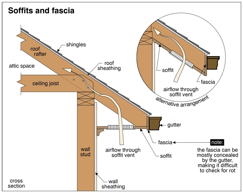 1813
1813Soffits and fascia
· p. 327
The cross section shows a roof eave with shingles and roof sheathing supported by a rafter above a framed exterior wall and ceiling joist. A horizontal vented soffit encloses the underside of the overhang, while fascia closes the rafter end behind the gutter. Arrows indicate airflow entering through the soffit vent and passing into the attic space. A circular inset shows an alternative arrangement with the vented soffit sloping along the underside of the rafter. A note explains that the gutter can mostly conceal the fascia, making inspection for rot difficult; no actual rot is depicted.
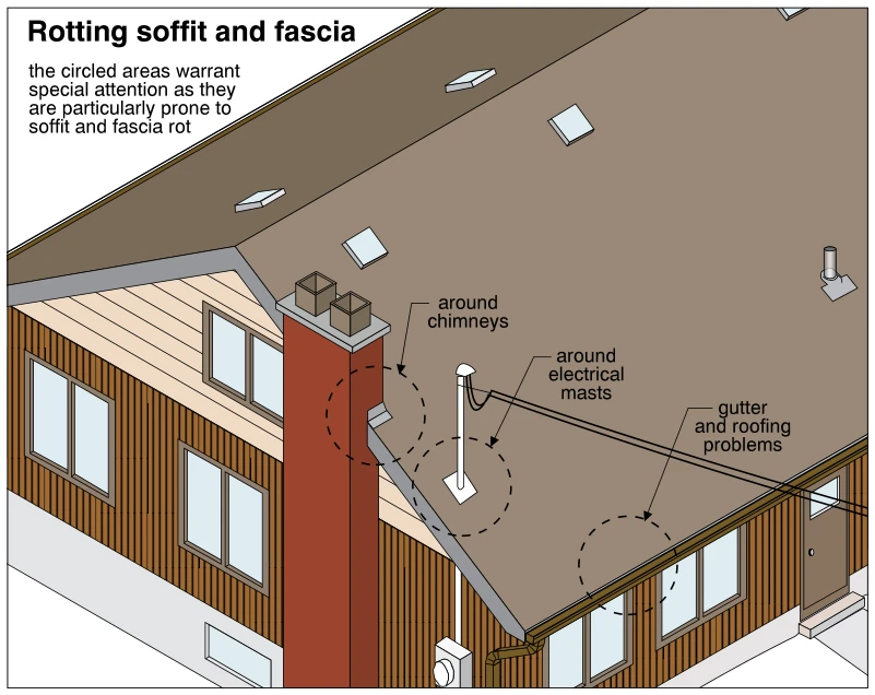 1814
1814Rotting soffit and fascia
· p. 327
The illustration shows a house with a sloped roof, an exterior chimney, an electrical service mast, and gutters along the eaves. Dashed circles identify locations particularly prone to soffit and fascia rot: near the chimney, around the electrical mast, and at an eave associated with gutter and roofing problems. The chimney intersects the roof edge, while the electrical mast penetrates the roof nearby and supports overhead service wires. These are inspection attention areas; detailed deterioration of the soffit or fascia is not drawn.
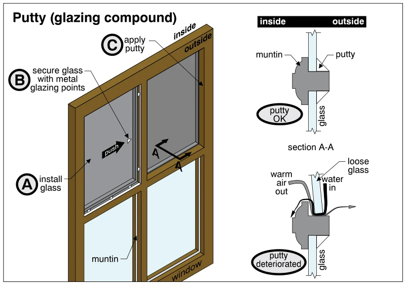 1815
1815Putty (glazing compound)
· p. 327
The illustration shows a divided-light window and the sequence of installing glass, securing it with metal glazing points, and applying glazing putty. The putty forms a beveled exterior seal between the glass and the window muntin. Section A-A compares intact putty with deteriorated putty at the glass-to-muntin joint. In the deteriorated condition, the glass is loose and arrows indicate warm air escaping and water entering through the failed joint.
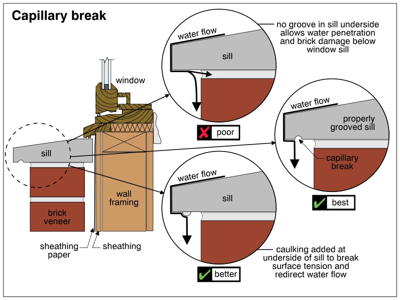 1816
1816Capillary break
· p. 327
A window and wall cross-section shows a projecting sill above brick veneer, with wall framing, sheathing, and sheathing paper behind the masonry. Three enlarged details compare how water flows over the sill edge and along its underside. The poor detail has no underside groove, allowing water to travel back toward the brickwork and cause water penetration and brick damage. The better detail adds caulking beneath the sill to break surface tension and redirect water downward. The best detail uses a groove in the sill underside as a capillary break, causing runoff to drop clear of the brick below.
Trim, Flashings and Caulkingp. 328
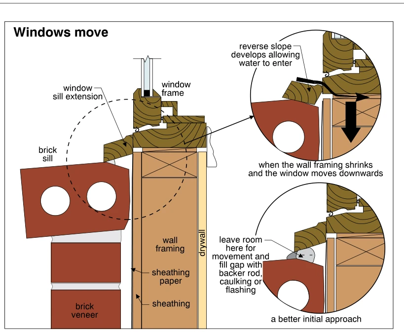 1817
1817Windows move
· p. 328
A wall section shows a wood window frame and sill extension above a brick sill in a brick-veneer wall, with framing, sheathing, sheathing paper and interior drywall identified. The upper detail shows the window moving downward as the wall framing shrinks while the brick sill supports the outer end of the sill extension. This creates a reverse slope that allows water to enter toward the window. The lower detail shows a better initial approach: leave clearance between the sill extension and brick sill for movement, and fill the gap with backer rod, caulking or flashing.
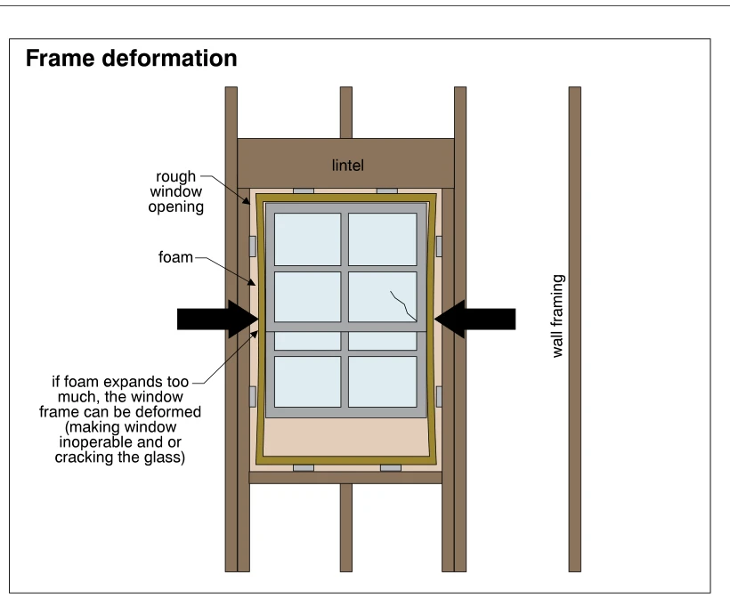 1818
1818Frame deformation
· p. 328
The illustration shows a window installed in a framed rough opening beneath a lintel, with foam filling the perimeter gap. Large inward-pointing arrows indicate pressure from excessive foam expansion against the window frame. The side members of the frame are bowed inward, and one glass pane is shown cracked. The annotation warns that excessive foam expansion can deform the frame, prevent window operation, or crack the glass.
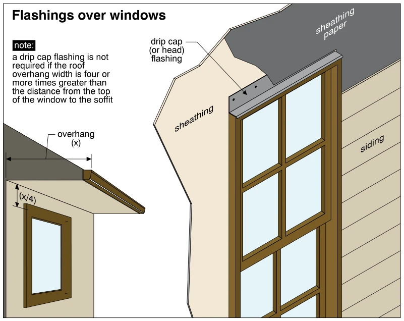 1819
1819Flashings over windows
· p. 328
The main drawing shows a drip cap, or head flashing, installed across the top of a window in a sided exterior wall. Its vertical leg extends up the wall sheathing beneath the sheathing paper, while its projecting lower edge covers the window head. Cutaway portions expose the relationship between the siding, sheathing paper, sheathing, and flashing. A smaller inset compares roof overhang width with the vertical distance from the window top to the soffit. The note states that drip cap flashing is not required when the overhang width is four or more times that distance.
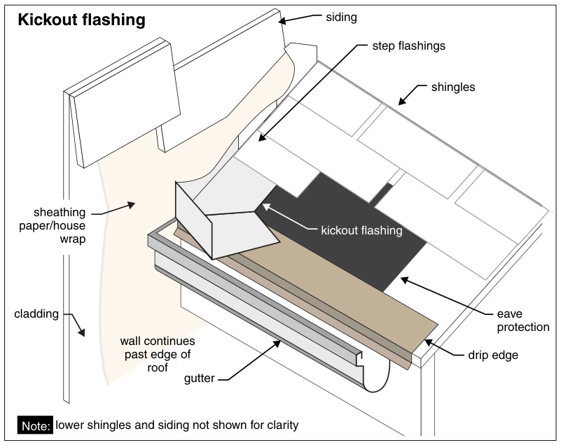 1819.5
Kickout flashing
· p. 328
The illustration shows a sloped shingle roof meeting a sidewall that continues past the roof eave. Step flashings follow the roof-to-wall intersection beneath the siding and overlap the kickout flashing at the lower end. The kickout flashing turns outward from the wall to direct runoff toward the gutter rather than down the wall cladding. Cutaway portions expose the sheathing paper/house wrap, eave protection, and drip edge; lower shingles and siding are omitted for clarity.
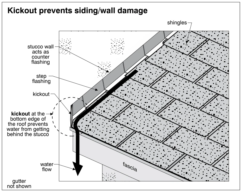 1820
1820Kickout prevents siding/wall damage
· p. 328
The illustration shows a shingle roof meeting a stucco wall along a sloping roof-to-wall intersection. Step flashing runs along the intersection, with the stucco wall acting as counter flashing over the vertical flashing legs. A kickout at the bottom edge redirects runoff away from the wall, preventing water from getting behind the stucco. A heavy arrow traces water down the flashing and outward over the eave beside the fascia; the gutter is explicitly not shown.
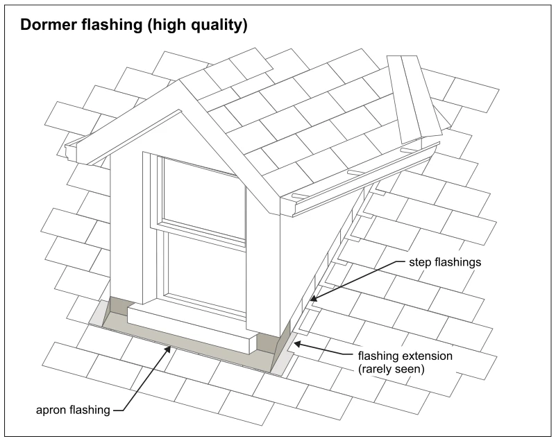 1820.3
Dormer flashing (high quality)
· p. 328
The illustration shows a gable-roof dormer projecting through a shingled sloping roof. Individual step flashings are interwoven with the roof shingles along the dormer sidewall. Apron flashing runs across the base of the dormer front, beneath the window and trim, and extends onto the roof below. A labeled flashing extension continues beside the lower sidewall and front corner. The detail is presented as a high-quality dormer flashing installation.
Exterior Structures ·Porches, Decks and Balconiesp. 329
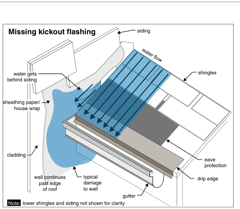 1820.6
Missing kickout flashing
· p. 329
The illustration shows a sloped shingle roof terminating against a wall that continues past the roof edge. Portions of the lower shingles and siding are omitted to expose the wall sheathing paper or house wrap, eave protection, drip edge, and gutter. Blue arrows trace runoff down the roof and along the roof-to-wall intersection. With kickout flashing missing at the lower end of this intersection, water gets behind the siding rather than being diverted away from the wall into the gutter. A blue area below the intersection identifies typical resulting wall damage.
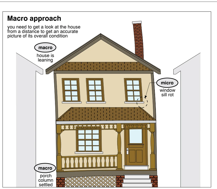 1821
1821Macro approach
· p. 329
The illustration shows a front elevation of a two-story house with a gable roof, brick chimney, and covered front porch. Macro-level callouts identify the leaning house and a settled porch column, emphasizing conditions visible when viewing the building from a distance. A micro-level callout points to localized rot at an upper-story window sill. The porch includes columns, railings, lattice skirting, masonry supports, and entrance steps. The drawing contrasts an overall assessment of building alignment and settlement with examination of an individual deteriorated component.
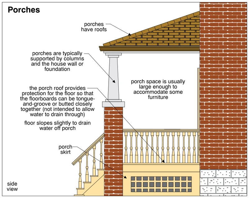 1822
1822Porches
· p. 329
The illustration shows a side view of a roofed porch attached to a brick house. A column on a brick pier supports the outer edge of the sloping porch roof, while the house wall forms the opposite side. The raised porch has a balustrade, access stairs with a railing, and a lattice skirt below the floor. Annotations explain that the roof protects closely fitted or tongue-and-groove floorboards and that the floor slopes slightly to drain water off the porch. The porch space is described as large enough to accommodate some furniture.
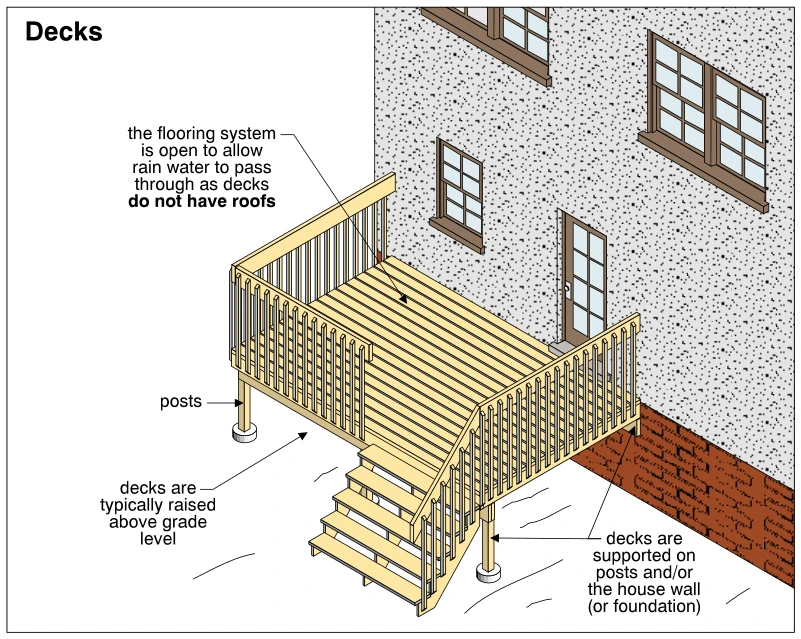 1823
1823Decks
· p. 329
The illustration shows an uncovered wood deck raised above grade beside a house, with access through an exterior door. Spaced deck boards allow rainwater to pass through the flooring. Guardrails with closely spaced vertical balusters surround the exposed deck edges, and a stairway with a railing descends to grade. Vertical posts rest on circular bases, and an annotation identifies posts and/or the house wall or foundation as deck supports. No specific defect is depicted.
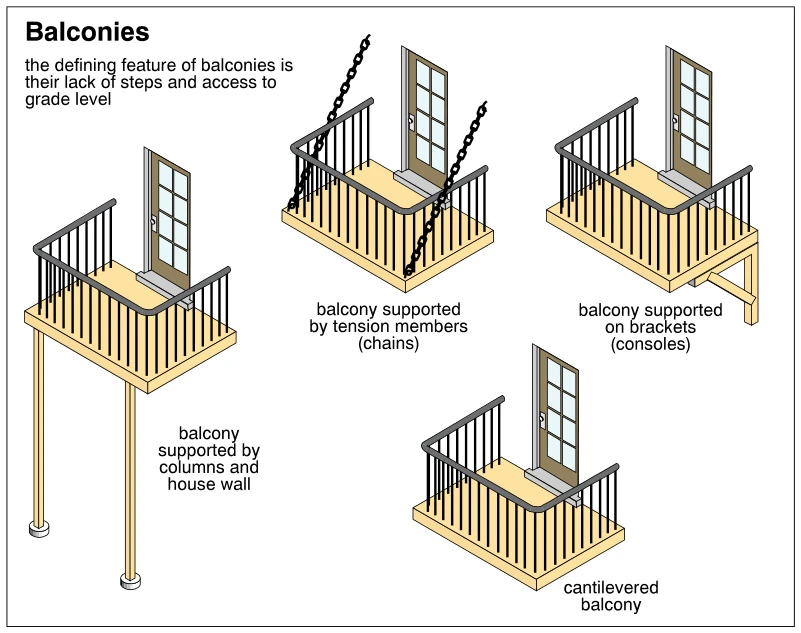 1824
1824Balconies
· p. 329
The illustration compares four balcony support arrangements: columns and the house wall, tension members shown as chains, brackets or consoles, and a cantilever. Each balcony has an elevated platform, perimeter guards with vertical balusters, and a glazed access door at the house side. The column-supported example has two tall posts bearing on small circular bases, while the bracket-supported example shows a diagonal brace beneath the platform. The chain-supported example hangs from inclined tension members, and the cantilevered example has no visible outer supports. The annotation identifies the lack of steps and access to grade level as the defining feature of balconies; no defects are indicated.
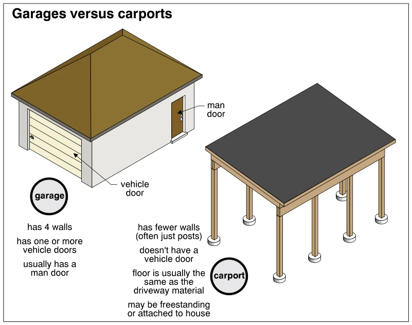 1825
1825Garages versus carports
· p. 329
The illustration compares an enclosed garage with an open-sided carport. The garage has four walls, a roof, a sectional vehicle door, and a separate pedestrian door labeled "man door." The carport has a roof supported by posts and perimeter beams, with the posts resting on individual round bases. Annotations distinguish the carport by its fewer walls, lack of a vehicle door, and floor that is usually the same material as the driveway. The text also notes that a carport may be freestanding or attached to a house.
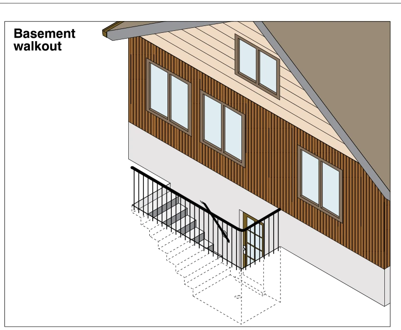 1826
1826Basement walkout
· p. 330
The illustration shows an exterior stairwell descending alongside a house foundation to a basement entrance door. Dashed lines outline the below-grade stair flight, stairwell enclosure, and bottom landing. A guard with closely spaced vertical balusters surrounds the exposed stairwell edge, and a sloping handrail follows the stairs along the foundation wall. A small circular opening is shown in the bottom landing, consistent with a stairwell drain. The house above has vertical wall siding, windows, and a gable with horizontal siding.
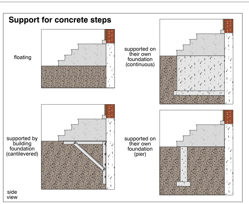 1827
1827Support for concrete steps
· p. 330
Four side-view sections illustrate alternative methods of supporting exterior concrete steps next to a building foundation. The floating steps rest directly on the ground without a separate foundation shown. A continuous foundation and spread footing support the steps in the upper-right example. The lower-left example uses a triangular cantilever support attached to the building foundation. The lower-right example shows the steps supported on a separate pier with a spread footing.
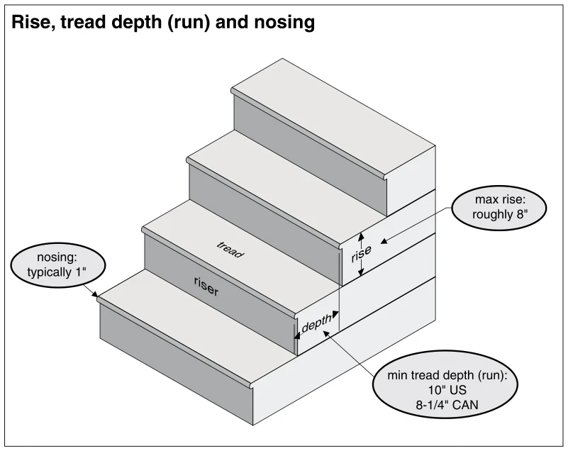 1828
1828Rise, tread depth (run) and nosing
· p. 330
The illustration shows a perspective view of a stair flight with solid risers and projecting tread nosings. Dimension arrows identify the vertical rise between adjacent treads and the horizontal tread depth, or run. A callout identifies the nosing projection as typically 1 inch. Additional annotations give a maximum rise of roughly 8 inches and minimum tread depths of 10 inches for the US and 8-1/4 inches for Canada. No specific defect is depicted.
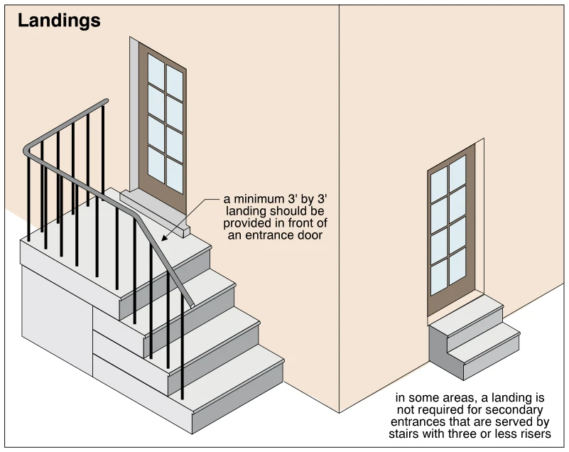 1829
1829Landings
· p. 330
The illustration shows two exterior entrance stair arrangements beside a building. The larger stairway has a level landing at the entrance door, with guards around the open landing edges and a handrail along the stairs. An annotation specifies a minimum landing size of 3 feet by 3 feet in front of an entrance door. The smaller stairway leads directly to a secondary entrance without a separate landing or railing. Its annotation notes that some areas do not require a landing at secondary entrances served by stairs with three or fewer risers.
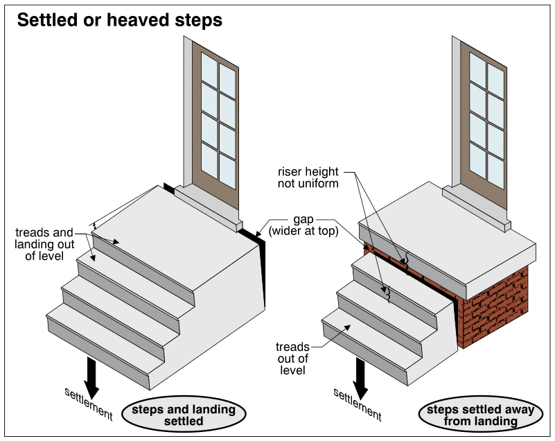 1830
1830Settled or heaved steps
· p. 330
Two diagrams depict settlement of exterior entrance steps beside a glazed door. On the left, the steps and landing have settled together, leaving the treads and landing out of level and a separation gap wider at the top against the building. On the right, the steps have settled away from a landing supported on brick masonry, leaving sloping treads and a gap at the landing junction. Callouts identify nonuniform riser heights, and downward arrows indicate settlement in both examples.
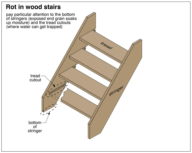 1831
1831Rot in wood stairs
· p. 330
The illustration shows an exterior wood stair assembly with four treads supported between two inclined stringers and open spaces between the treads. A cutaway at the lower left stringer exposes a tread cutout, with dashed lines highlighting the cutout and the stringer bottom. The annotation identifies these locations as particularly susceptible to rot: exposed end grain at the stringer bottom absorbs moisture, while tread cutouts can trap water. The drawing emphasizes where to inspect for decay rather than showing detailed decay texture.
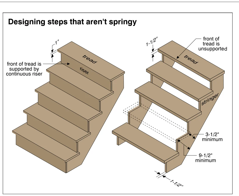 1832
1832Designing steps that aren't springy
· p. 331
The illustration compares wood stairs with continuous risers to open-riser stairs, showing construction dimensions intended to limit springiness. On the left, continuous risers support the fronts of the treads, which are labeled as 1 inch thick. On the right, the tread fronts have no riser support, and the treads are labeled as 1-1/2 inches thick. A tread is shown in dashed outline to expose the notched stringers, with minimum dimensions of 3-1/2 inches at the remaining stringer depth and 9-1/2 inches across the overall stringer depth. The stringer thickness is labeled as 1-1/2 inches.
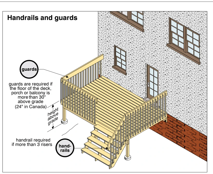 1833
1833Handrails and guards
· p. 331
The illustration shows an elevated wood deck attached to a house, with an exterior stair descending to grade. Guards with closely spaced vertical balusters surround the exposed deck edges, and a sloping railing follows one side of the stairs. Posts support the deck and stair railing, with visible round concrete footings beneath two posts. An annotation measures deck height above grade and states guard requirements at heights greater than 30 inches, or 24 inches in Canada. Another annotation states that a handrail is required if there are more than three risers.
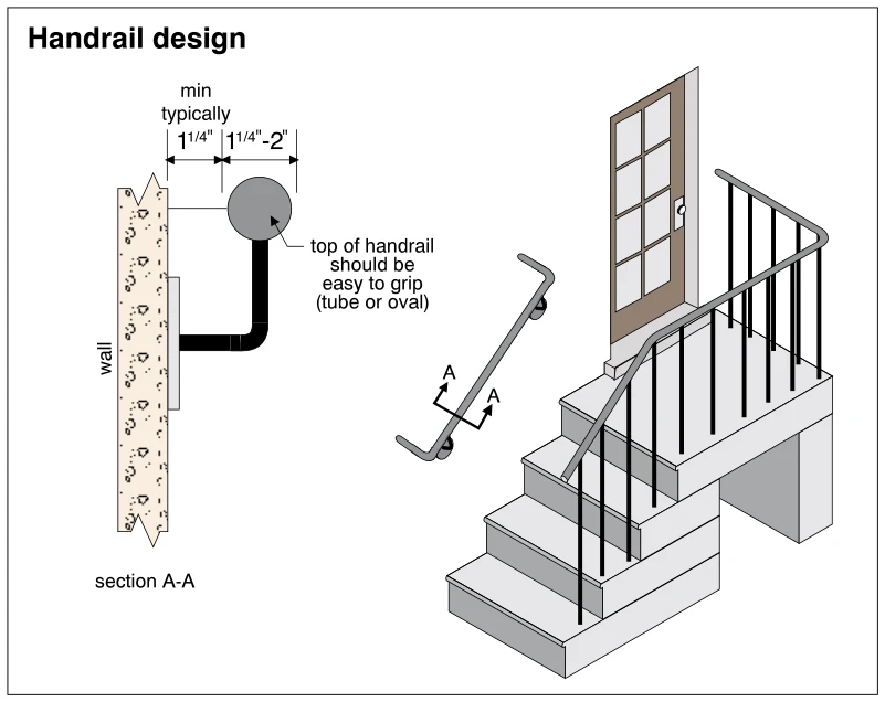 1834
1834Handrail design
· p. 331
The illustration shows exterior entrance stairs and a landing with an open-sided railing and a separate wall-mounted handrail. Section A-A details a round handrail supported away from the wall by a bent bracket. The detail indicates a typical minimum wall clearance of 1¼ inches and a handrail width of 1¼ to 2 inches. An annotation specifies that the top of the handrail should be easy to grip, with a tube or oval profile. The wall-mounted rail has curved ends, while the outer railing follows the stair slope and continues around the landing.
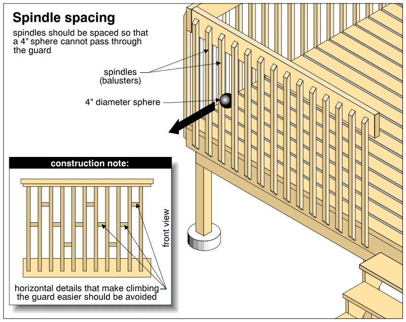 1835
1835Spindle spacing
· p. 331
The illustration shows a raised wood deck with a guard consisting of vertical spindles, an upper rail, and a lower framing member. A 4-inch-diameter sphere demonstrates that the openings between spindles should be small enough to prevent the sphere from passing through the guard. Deck boards, a support post on a round footing, and part of the deck stairs are also visible. An inset front view shows short horizontal pieces between the spindles and warns against details that make the guard easier to climb.
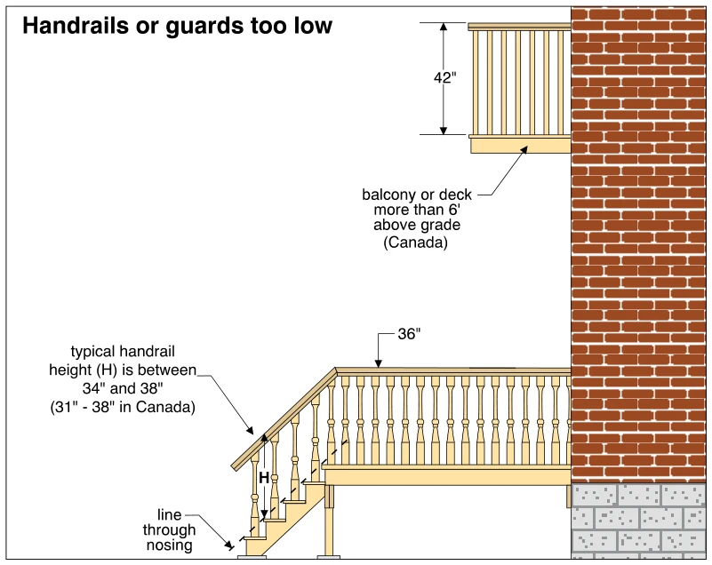 1836
1836Handrails or guards too low
· p. 331
The illustration shows an exterior stair and deck beside a brick wall, with a separate elevated balcony or deck guard above. The stair handrail height H is measured vertically from the line through the stair nosings to the sloping handrail. An annotation gives a typical handrail height of 34 to 38 inches, with 31 to 38 inches stated for Canada. The lower deck guard is labeled 36 inches, while the upper guard is dimensioned 42 inches for a balcony or deck more than 6 feet above grade in Canada. Although the title identifies insufficient railing height as the inspection concern, the drawing presents height references rather than explicitly dimensioning an undersized railing.
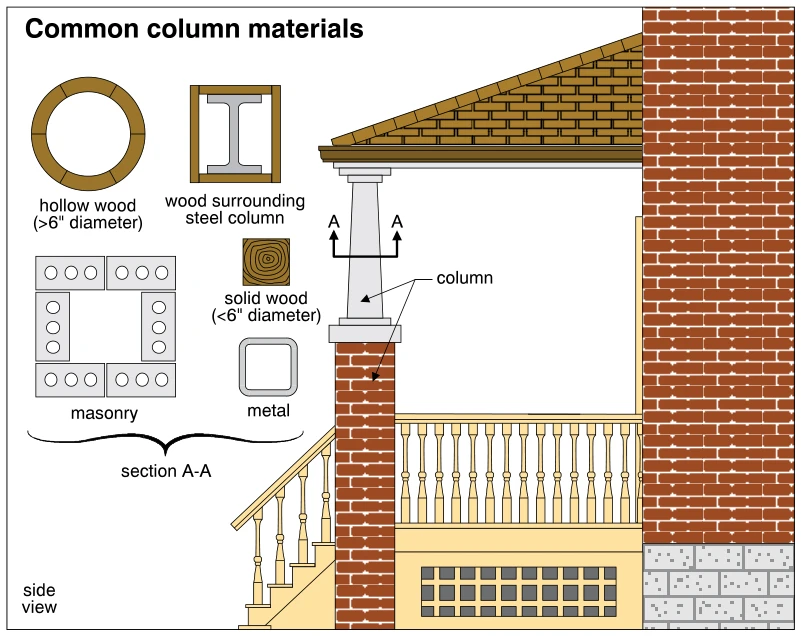 1837
1837Common column materials
· p. 331
The illustration shows a side view of a roofed porch adjoining a brick house, with stairs, balustrades, and lattice beneath the porch deck. A tapered column supports the outer edge of the porch roof and rests on a capped brick pier. Section A-A identifies the column cross-section location, with separate diagrams illustrating common column materials and configurations. These include hollow wood greater than 6 inches in diameter, solid wood less than 6 inches in diameter, wood surrounding a steel column, masonry, and hollow metal. No defects or improper installation practices are identified.
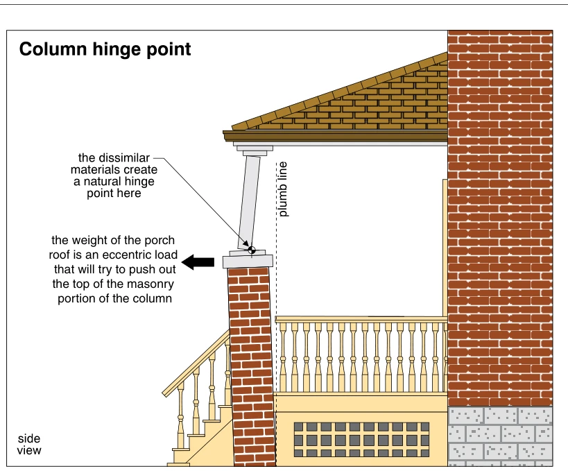 1838
1838Column hinge point
· p. 332
The side-view illustration shows a porch roof supported at its outer edge by an upper post bearing on a capped brick masonry column. The junction between the dissimilar materials is marked as a natural hinge point. A dashed plumb line shows the masonry column leaning outward, while the upper post slopes back toward the roof support. An outward-pointing arrow indicates how the eccentric roof load tends to push the top of the masonry column away from the house. Porch stairs, railings, lattice skirting, and the adjoining brick house wall and foundation provide context.
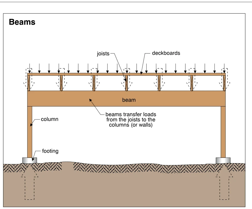 1839
1839Beams
· p. 332
The illustration shows a deck framing assembly with deckboards resting on joists supported by a horizontal beam. Downward arrows indicate loads passing through the decking and joists to the beam. The beam spans between two columns, which bear on footings shown extending below grade with dashed outlines. An annotation explains that beams transfer loads from the joists to columns or walls. No defects or improper practices are identified.
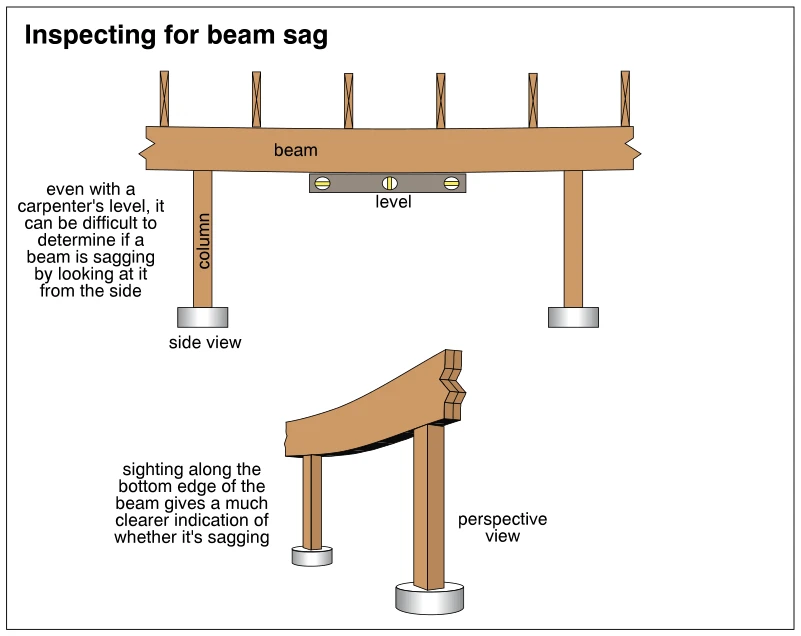 1840
1840Inspecting for beam sag
· p. 332
The illustration shows a wood beam supported by two columns on individual bases, in side and perspective views. In the side view, a carpenter's level is held against the underside near midspan, and several framing members extend above the beam. The annotation explains that beam sag can be difficult to detect from the side, even with a level. The perspective view emphasizes the curved bottom edge and illustrates sighting along that edge to better identify sag between supports.
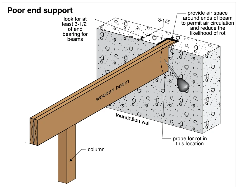 1841
1841Poor end support
· p. 332
A built-up wooden beam rests on a column and extends into a pocket in a concrete foundation wall. The drawing identifies a minimum end-bearing length of 3-1/2 inches at the wall. An annotation calls for air space around the beam end to promote circulation and reduce the likelihood of rot. A probing tool is shown at the beam near the wall pocket, indicating where to check for decay. The illustration highlights inspection concerns at beam end supports without showing a confirmed bearing deficiency or visible rot.
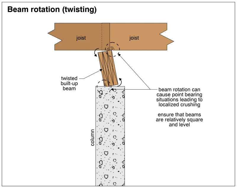 1842
1842Beam rotation (twisting)
· p. 332
The illustration shows a built-up wood beam supporting joists and bearing on a concrete column. The beam is rotated out of square, with curved arrows indicating twisting. Its tilted position concentrates contact at the joists above and the column below rather than providing broad bearing surfaces. An annotation warns that this point bearing can lead to localized crushing and advises keeping beams relatively square and level.
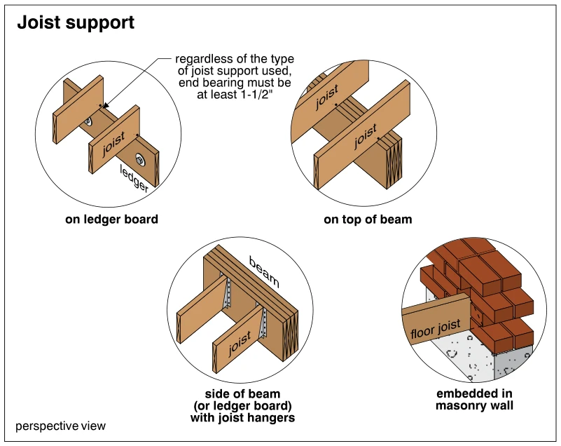 1843
1843Joist support
· p. 332
Four perspective details illustrate methods of supporting wood joists. The upper details show joists bearing on a ledger board and on top of a beam. The lower details show joists attached to the side of a beam or ledger board with metal joist hangers, and a floor joist embedded in a masonry wall. An annotation specifies that end bearing must be at least 1-1/2 inches regardless of the type of joist support used.
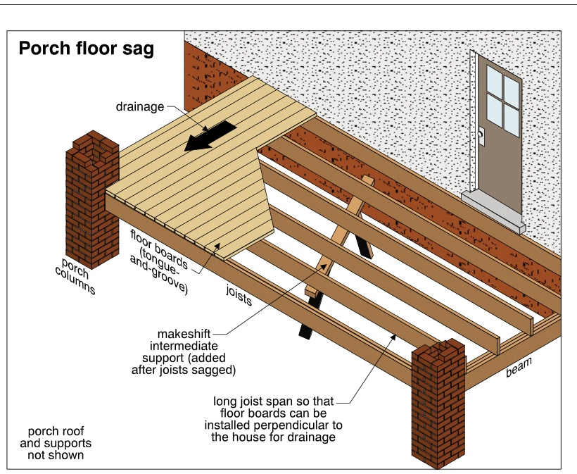 1844
1844Porch floor sag
· p. 333
The illustration shows a partially exposed wood porch floor beside a house entrance, with tongue-and-groove floor boards installed perpendicular to the house for outward drainage. The exposed joists run parallel to the house and span between end supports, with a beam and brick porch columns shown. An annotation identifies the long joist span associated with this floor-board orientation. A makeshift intermediate support has been added beneath the joists after they sagged. The porch roof and its supports are explicitly omitted.
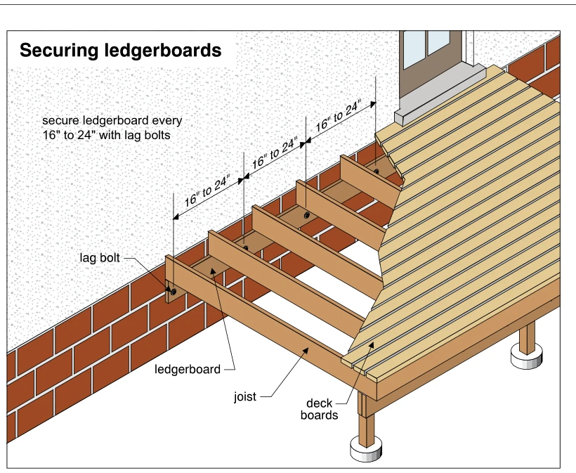 1845
1845Securing ledgerboards
· p. 333
The illustration shows a wood deck attached to a building with a ledgerboard along the exterior wall. Part of the decking is cut away to expose the ledgerboard, lag bolts, and joists extending outward from the building. An annotation specifies securing the ledgerboard with lag bolts every 16 to 24 inches, with repeated dimension arrows indicating this spacing along the wall. Deck boards cover the remaining framing, and the outer deck edge is supported by wood posts on round concrete supports. A doorway opens onto the deck.
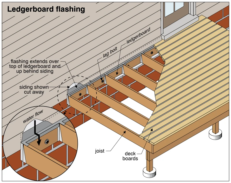 1846
1846Ledgerboard flashing
· p. 333
The illustration shows a wood deck attached to an exterior wall by a ledgerboard secured with lag bolts. Cutaway siding and deck boards expose the flashing, ledgerboard, and deck joists. Flashing extends up behind the siding and over the top of the ledgerboard, with its outer edge turned down over the ledger face. An enlarged inset uses a water-flow arrow to show water being directed over the flashing and away from the ledgerboard's top. Deck boards span the joists, and posts on circular footings support the outer deck framing.
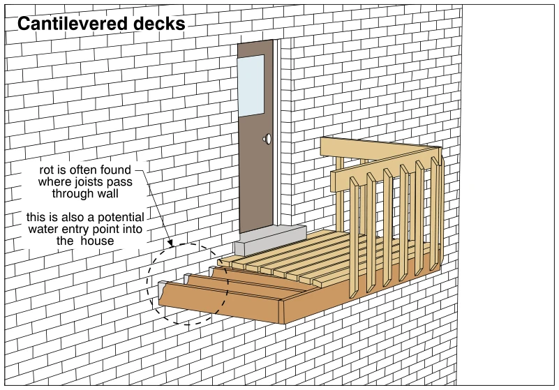 1847
1847Cantilevered decks
· p. 333
The illustration shows a wood cantilevered deck projecting from a masonry-clad exterior wall outside a door. Part of the decking is omitted to expose the supporting joists extending through the wall, with no exterior support posts shown. A wood guard with vertical balusters encloses the visible outer edges. A dashed circle highlights the joist penetrations at the wall, where annotations identify susceptibility to rot and potential water entry into the house.
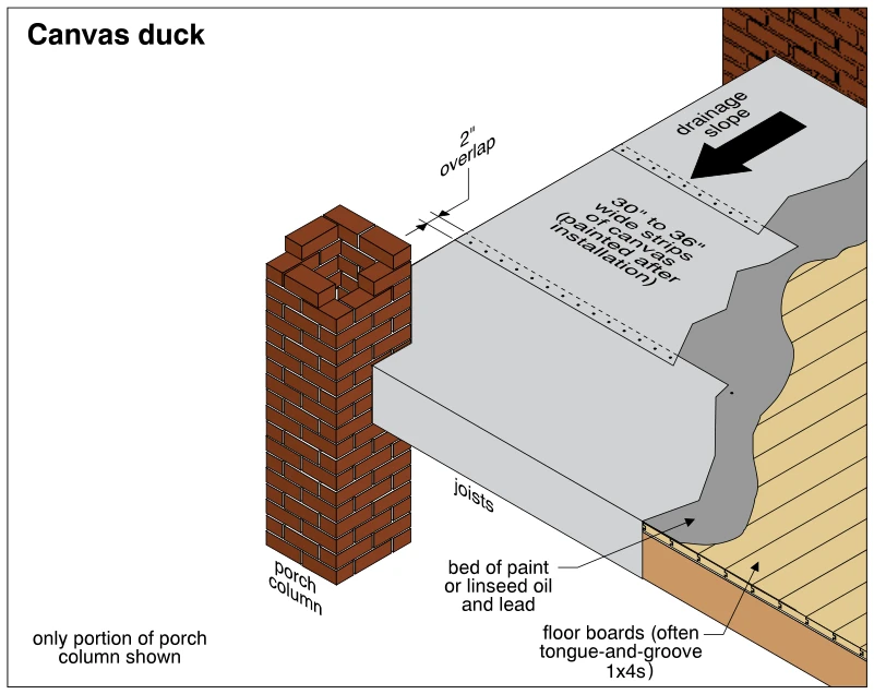 1848
1848Canvas duck
· p. 333
The illustration shows a canvas-duck covering over a wood porch or deck floor beside brick masonry. Cutaway layers expose floor boards, identified as often tongue-and-groove 1x4s, supported by joists. The canvas is laid in a bed of paint or linseed oil and lead, using 30- to 36-inch-wide strips with 2-inch overlaps, and painted after installation. An arrow indicates the drainage slope across the lapped covering. A partially shown brick porch column stands at the outer edge.
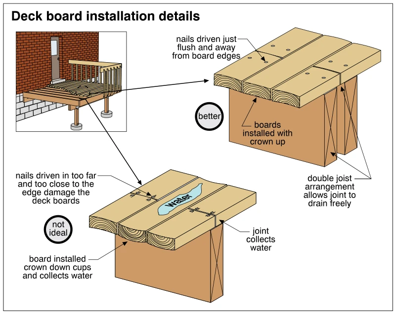 1849
1849Deck board installation details
· p. 333
The illustration compares two wood deck board installation details, with an inset locating the decking on an exterior deck. The better detail shows boards installed crown up, with nails driven flush and set away from board edges. A double-joist arrangement allows the board end joint to drain freely. The less desirable detail shows a crown-down board cupping and collecting water, along with a board end joint that retains water over its support. Overdriven nails placed too close to board edges are shown damaging the decking.
Exterior Structures ·Garages and Carportsp. 334
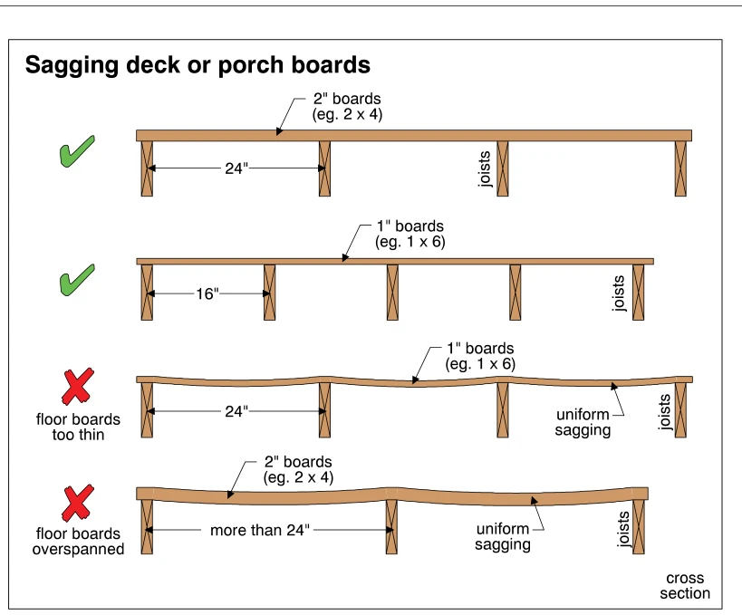 1850
1850Sagging deck or porch boards
· p. 334
Four cross sections compare deck or porch board thickness and joist spacing. Green check marks identify straight 2-inch boards over joists spaced 24 inches apart and straight 1-inch boards over joists spaced 16 inches apart. A red X marks 1-inch boards spanning 24 inches, with uniform sagging between joists and an annotation identifying the floor boards as too thin. Another red X marks 2-inch boards spanning more than 24 inches, also sagging uniformly between supports and identified as overspanned.
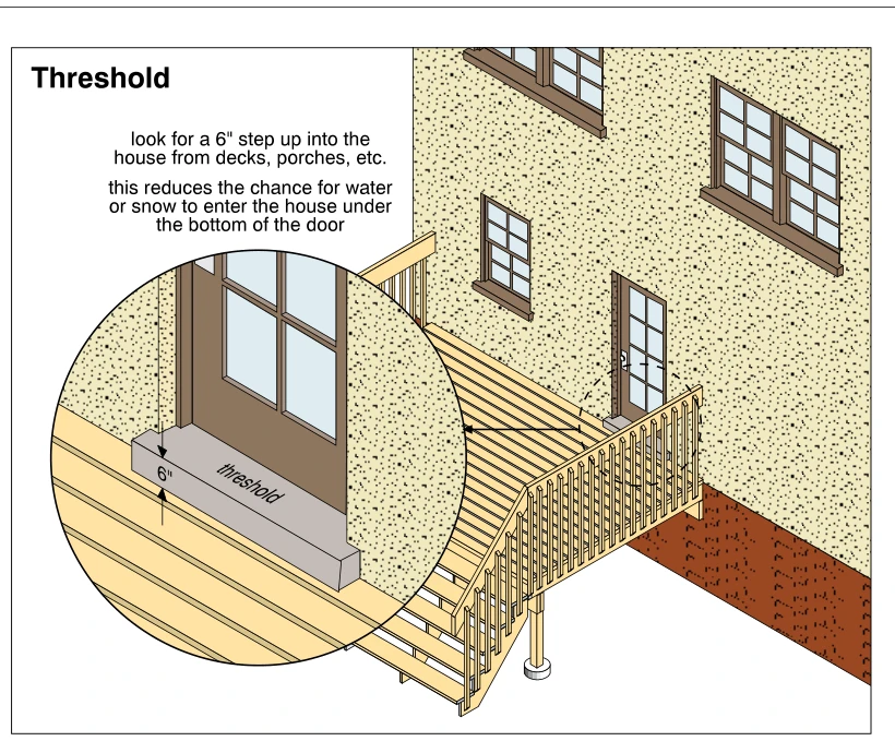 1851
1851Threshold
· p. 334
The illustration shows an exterior house door opening onto a raised wood deck with stairs and guardrails. A magnified detail shows the door threshold elevated 6 inches above the adjacent deck surface. The annotations recommend this step up from decks and porches to reduce the chance of water or snow entering beneath the door. The threshold spans the doorway at the base of the door and projects beyond the exterior wall surface.
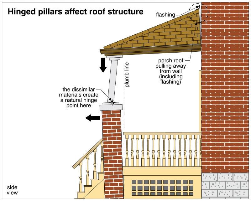 1852
1852Hinged pillars affect roof structure
· p. 334
The side-view illustration shows a porch roof supported by a column seated on a tall brick pillar beside the house wall. The junction between the dissimilar support materials is identified as a natural hinge point. The brick pillar leans outward relative to a dashed plumb line, while the upper column tilts at its connection to the pillar cap. Arrows indicate outward movement of the pillar and downward movement of the roof support. At the house wall, the porch roof and flashing are shown pulling away from the masonry.
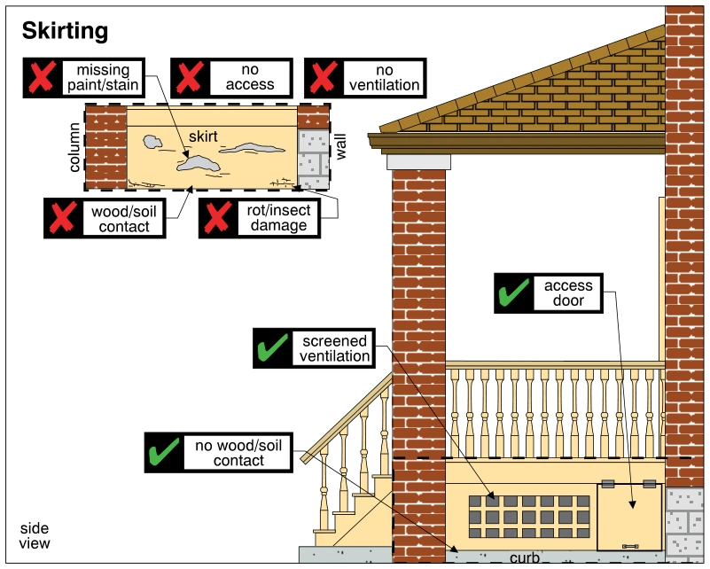 1853
1853Skirting
· p. 334
The illustration compares proper and improper skirting beneath an elevated porch. The main side view shows skirting between a brick column and the house wall, with screened ventilation and a hinged access door. A curb separates the wood skirting from the soil, and stairs and a balustrade serve the porch above. An inset shows defective skirting with missing paint or stain, wood-to-soil contact, and rot or insect damage. The inset also identifies the lack of access and ventilation as improper conditions.
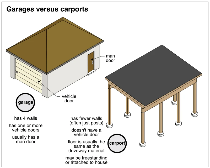 1854
1854Garages versus carports
· p. 334
The illustration compares an enclosed garage with an open-sided carport. The garage has a pitched roof, perimeter walls, a sectional vehicle door, and a separate pedestrian door labeled "man door." The carport has a roof supported by exposed posts and perimeter beams, with the posts resting on individual circular bases. Annotations explain that garages have four walls and vehicle doors, while carports have fewer walls, often only posts, and no vehicle door. The carport notes also state that its floor is usually the same material as the driveway and that it may be freestanding or attached to a house.
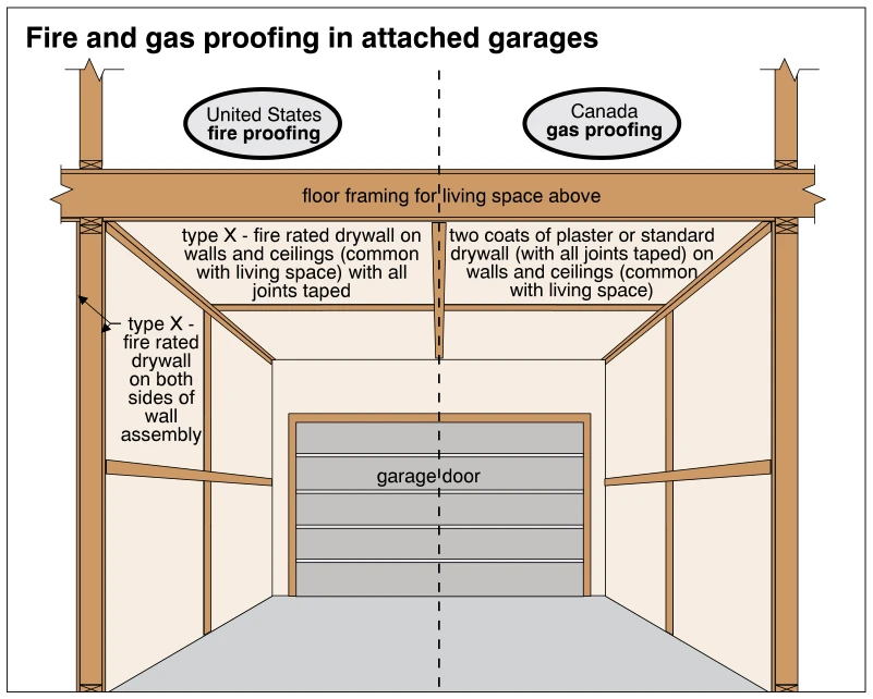 1855
1855Fire and gas proofing in attached garages
· p. 334
The illustration shows an attached garage interior with floor framing for living space above and a sectional garage door at the far end. A dashed vertical line divides a comparison of United States fire proofing and Canadian gas proofing. The United States side calls for Type X fire-rated drywall with taped joints on walls and ceilings common with living space, and identifies drywall on both sides of the wall assembly. The Canadian side identifies two coats of plaster or standard drywall with all joints taped on walls and ceilings common with living space.
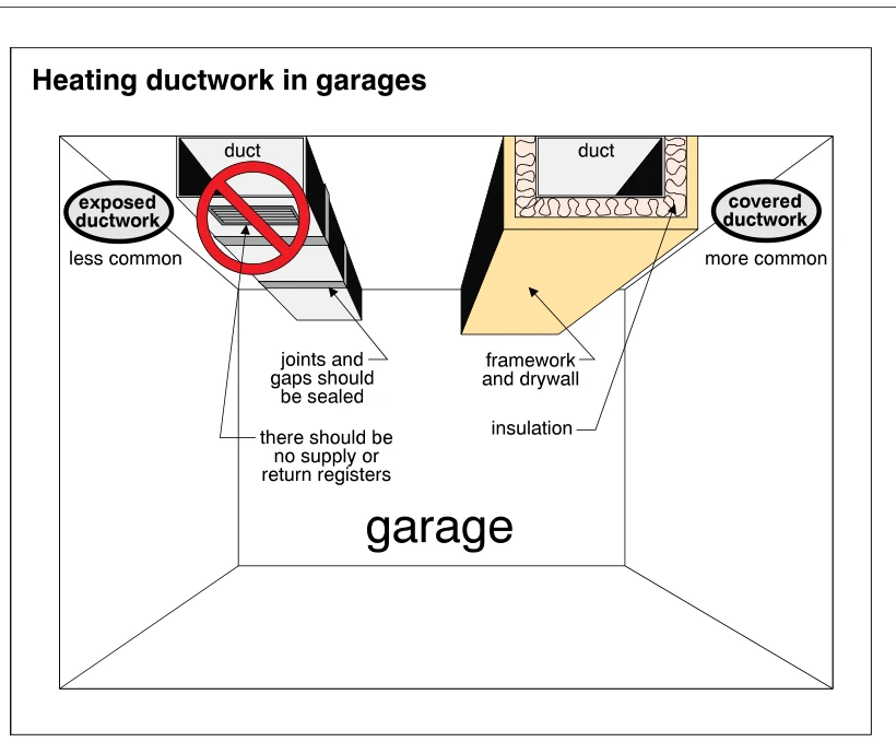 1856
1856Heating ductwork in garages
· p. 335
The illustration compares exposed and covered heating ductwork running overhead in a garage. The exposed ductwork, identified as less common, has joints and gaps that should be sealed. A red prohibition symbol over a register emphasizes that there should be no supply or return registers in the garage. The more common covered arrangement shows a duct surrounded by insulation and enclosed with framework and drywall.
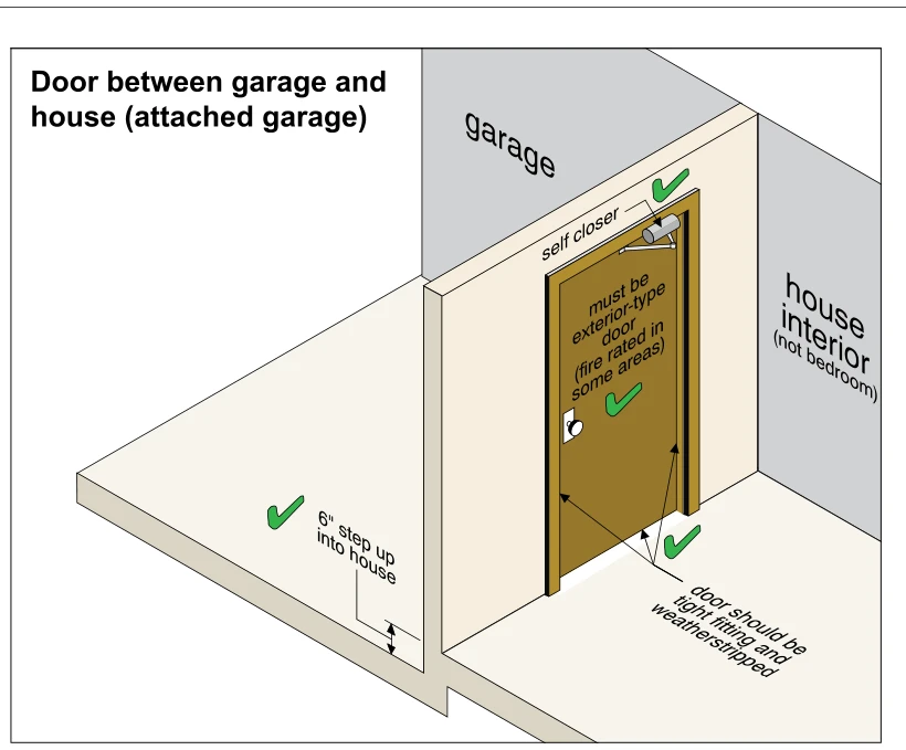 1857
1857Door between garage and house (attached garage)
· p. 335
The illustration shows a door in the separating wall between an attached garage and the house interior. Green check marks identify an exterior-type door, noted as fire rated in some areas, with a self closer at the top. Arrows indicate that the door should be tight fitting and weatherstripped. The house floor is shown with a labeled 6-inch step up from the garage floor. The interior space reached through the door is explicitly labeled as not a bedroom.
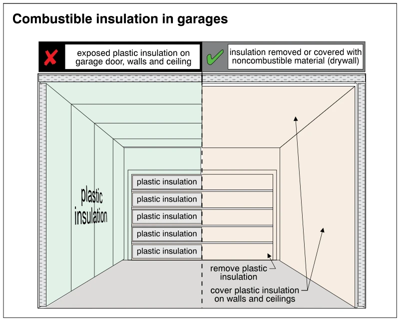 1858
1858Combustible insulation in garages
· p. 335
The illustration presents a split comparison of a garage interior with exposed plastic insulation on the left and corrected conditions on the right. A red X identifies exposed insulation on the garage door, walls, and ceiling as improper. The right half, marked with a green check, shows wall and ceiling insulation covered with noncombustible material identified as drywall. An arrow at the garage door directs removal of its plastic insulation, while arrows at the wall and ceiling direct covering the insulation.
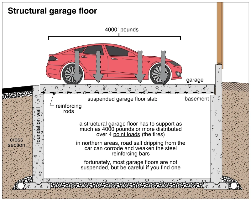 1859
1859Structural garage floor
· p. 335
The cross section shows a car on a suspended reinforced-concrete garage floor spanning foundation walls above a basement. Downward arrows illustrate vehicle weight applied through four tire point loads, with the car labeled as weighing 4000 pounds or more. Reinforcing rods are shown near the underside of the slab. The surrounding assembly includes foundation walls, footings, a basement floor, granular base, and perimeter drainage pipes. Annotations warn that road salt dripping from vehicles can corrode and weaken the steel reinforcement, although no actual deterioration is drawn.
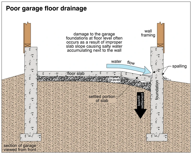 1860
1860Poor garage floor drainage
· p. 335
A front-view section of a garage shows a concrete floor slab supported on gravel and soil between foundation walls with footings and wood wall framing above. Backfill settlement beneath the right side has allowed a portion of the slab to drop and slope toward the foundation wall. A water-flow arrow shows drainage toward this low area beside the wall rather than away from it. Spalling is depicted on the foundation near slab level, and the annotation links this damage to salty water accumulating against the wall because of improper slab slope.
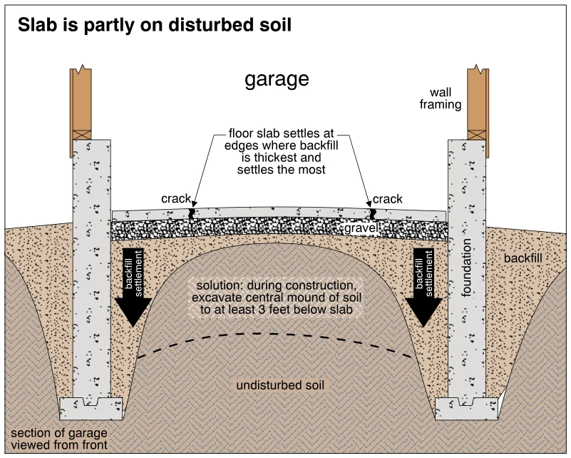 1861
1861Slab is partly on disturbed soil
· p. 335
A front-view section of a garage shows a concrete floor slab on gravel between foundation walls and footings supporting wall framing. Beneath the slab, a central mound of undisturbed soil is flanked by thicker backfill near the foundations. Downward arrows indicate backfill settlement, and cracks mark where the slab's outer portions settle relative to its center. A dashed excavation profile illustrates the annotated construction solution: excavate the central mound to at least 3 feet below the slab.
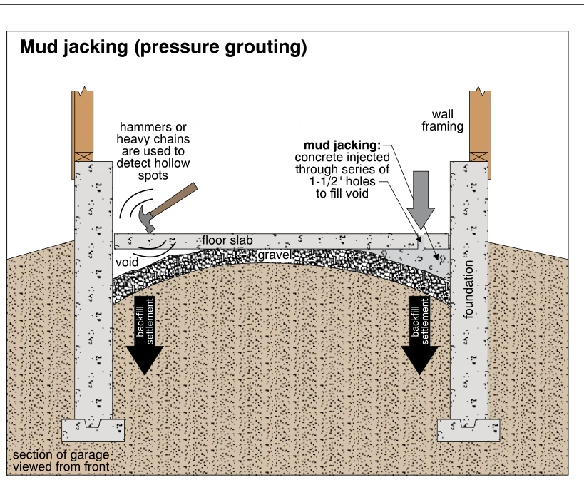 1862
1862Mud jacking (pressure grouting)
· p. 336
The illustration shows a front-view section through a garage floor slab between foundation walls and footings, with wall framing above. Gravel and backfill beneath the slab have settled near the foundation walls, leaving voids under the slab. A hammer illustrates sounding the slab to detect hollow spots; the annotation also identifies heavy chains as a detection method. At the right, an injection arrow illustrates mud jacking, with concrete injected through a series of 1-1/2-inch holes to fill the void beneath the slab.
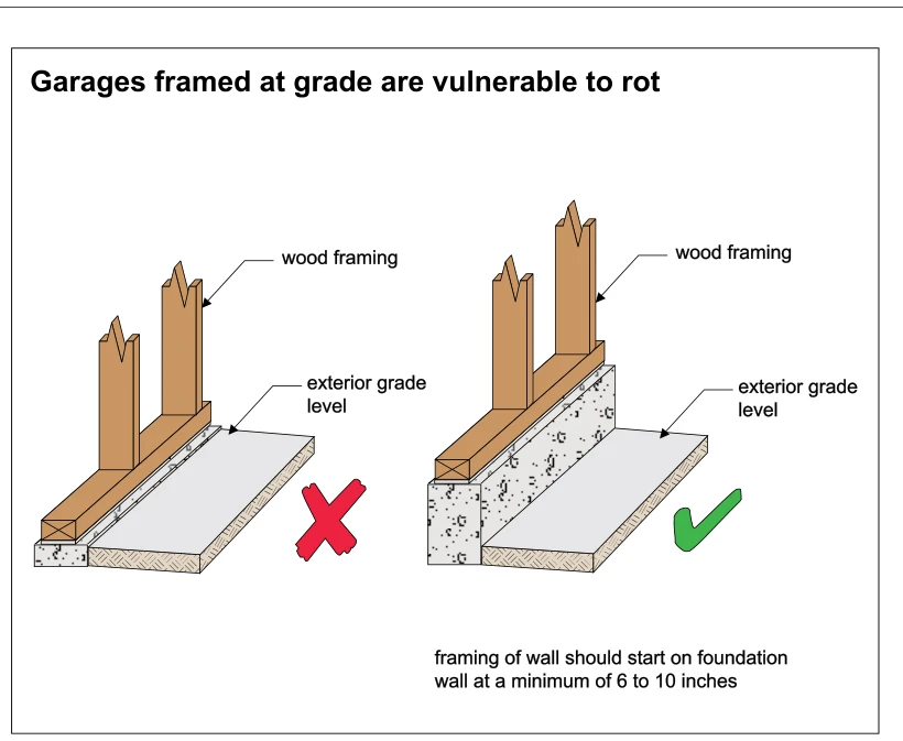 1862.5
Garages framed at grade are vulnerable to rot
· p. 336
The illustration compares two garage wall framing arrangements relative to exterior grade. On the left, wood studs and a bottom plate rest on a low concrete foundation at approximately grade level, marked with a red X to indicate vulnerability to rot. On the right, a taller concrete foundation wall elevates the wood framing above exterior grade, marked with a green check. An annotation specifies that wall framing should start on the foundation wall at a minimum of 6 to 10 inches above grade.
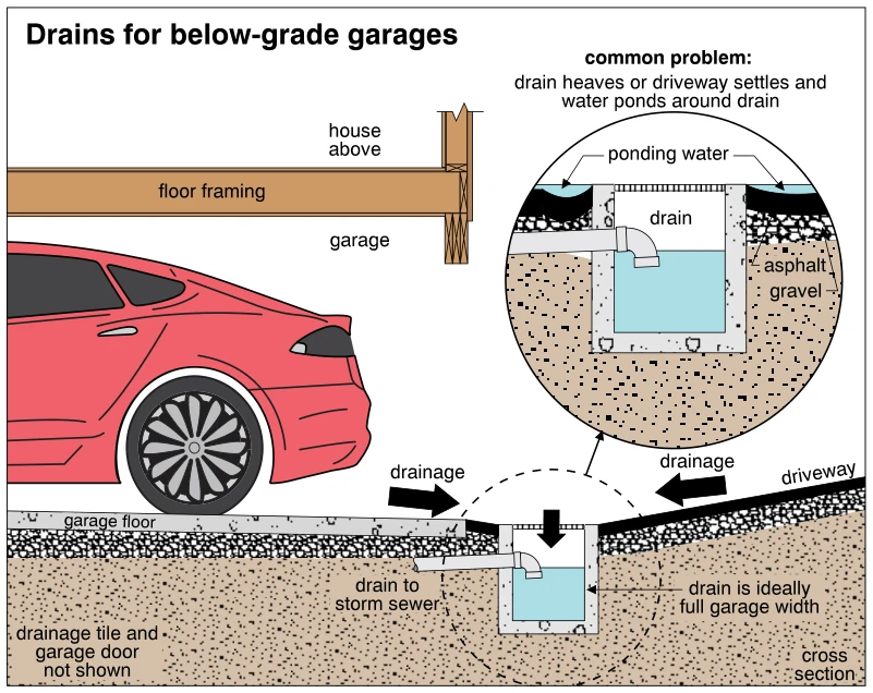 1863
1863Drains for below-grade garages
· p. 336
The cross section depicts a below-grade garage beneath a house, with a grated drain at the junction of the garage floor and the sloping driveway. Arrows show drainage toward the inlet from both the garage floor and driveway, and an outlet pipe is labeled as draining to the storm sewer. The drawing notes that the drain ideally extends the full garage width and that drainage tile and the garage door are not shown. An enlarged detail illustrates a common failure condition in which the drain heaves or the driveway settles, leaving water ponding beside the elevated grate.
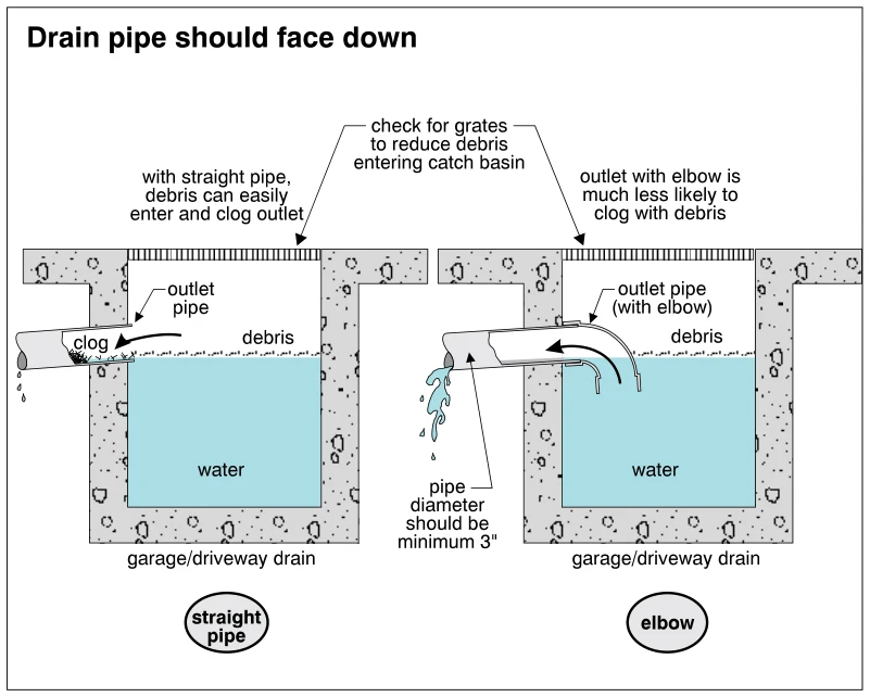 1864
1864Drain pipe should face down
· p. 336
Two cross-sectional drawings compare outlet arrangements in grated garage/driveway catch basins. The left basin has a straight outlet pipe at the water surface, allowing floating debris to enter and clog the outlet; only drops discharge from the pipe. The right basin has a downward-facing elbow with its opening below the floating debris layer, reducing the likelihood of blockage and allowing water to discharge. Both basins are shown with concrete walls and top grates, with an annotation advising checks for grates to reduce debris entry. The illustration specifies a minimum outlet pipe diameter of 3 inches.
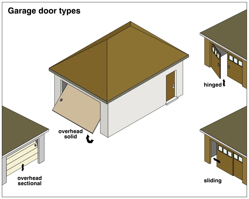 1865
1865Garage door types
· p. 336
The illustration depicts four types of residential garage vehicle doors. A central garage has a one-piece solid overhead door shown partially tilted outward, with a curved arrow indicating its opening motion. A lower-left detail shows a sectional overhead door made of horizontal panels, with an arrow indicating vertical movement. The upper-right detail shows paired hinged doors, one swung outward, while the lower-right detail shows sliding door panels with a horizontal movement arrow. The figure identifies operating configurations rather than defects or installation practices.
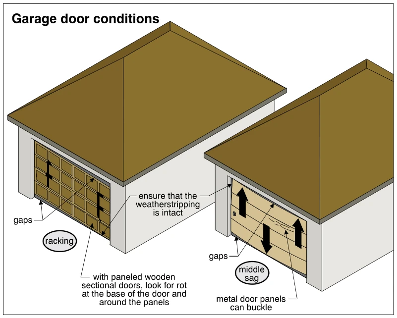 1866
1866Garage door conditions
· p. 336
Two garage illustrations show common conditions affecting sectional garage doors. The paneled wooden door on the left depicts racking, with opposing vertical arrows and gaps around the door opening. An annotation calls for checking for rot at the door base and around the wood panels. The metal door on the right depicts middle sag, gaps, and possible buckling of the panels. A shared callout instructs the inspector to ensure that the weatherstripping is intact.
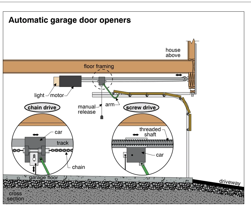 1867
1867Automatic garage door openers
· p. 337
The illustration shows a cross section of an automatic sectional garage door opener beneath floor framing, with living space above the garage. A motor and light assembly connects to a horizontal opener track, with a traveling car linked to the door by an arm. A manual-release cord hangs from the car, and the sectional door follows a curved track from vertical to overhead. Two enlarged details compare chain-drive and screw-drive mechanisms: one moves the car with a chain, while the other uses a threaded shaft. No installation defect is identified.
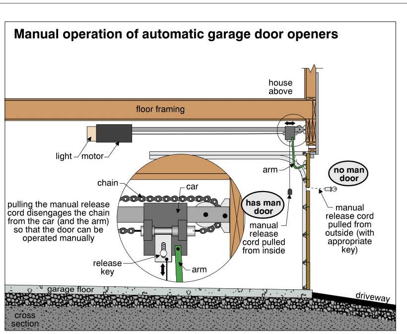 1868
1868Manual operation of automatic garage door openers
· p. 337
A cross section shows an automatic garage door opener mounted beneath floor framing, with its drive rail and connecting arm extending to the garage door. An enlarged detail shows the chain, car, arm, and release key that allow the drive to be disengaged for manual door operation. Where the garage has a pedestrian entry door, the manual release cord is pulled from inside. Where there is no pedestrian entry door, the illustration shows a keyed release accessible from outside.
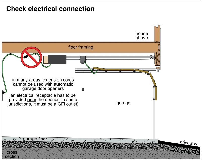 1869
1869Check electrical connection
· p. 337
A cross section of an attached garage shows an automatic garage door opener mounted beneath the floor framing of the house above. The opener's rail and connecting arm operate a sectional overhead door riding in curved tracks, with a release cord hanging below the rail. An extension cord runs from a wall receptacle to the opener, and a red prohibition symbol marks the cord connection as improper. The annotations state that extension cords cannot be used for automatic garage door openers in many areas and that a receptacle must be provided near the opener, with a GFI outlet required in some jurisdictions.
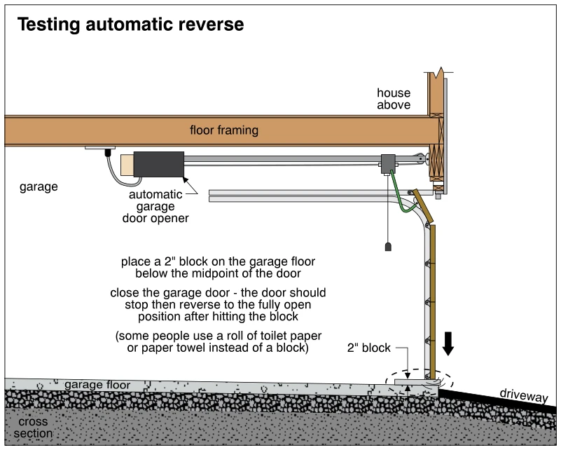 1870
1870Testing automatic reverse
· p. 337
A cross section shows an automatic sectional garage door and ceiling-mounted opener beneath the floor framing of a house. The opener rail and connecting arm operate the door along its curved track, and a downward arrow indicates closing travel. A 2-inch block is positioned on the garage floor beneath the midpoint of the door to test contact-triggered automatic reversal. The annotations state that the door should stop after hitting the block and then reverse to the fully open position; they also note that some people substitute a roll of toilet paper or paper towel. No failed reversal or damaged component is depicted.
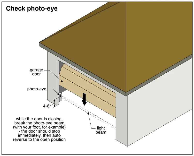 1871
1871Check photo-eye
· p. 337
The illustration shows a partially closed sectional garage door with a downward arrow indicating closing movement. A photo-eye is mounted near the base of the door opening, with a indicated mounting height of 4–6 inches. Dashed lines represent the light beam extending across the opening. The annotation instructs the inspector to interrupt the beam while the door is closing; the door should stop immediately and automatically reverse to the open position.
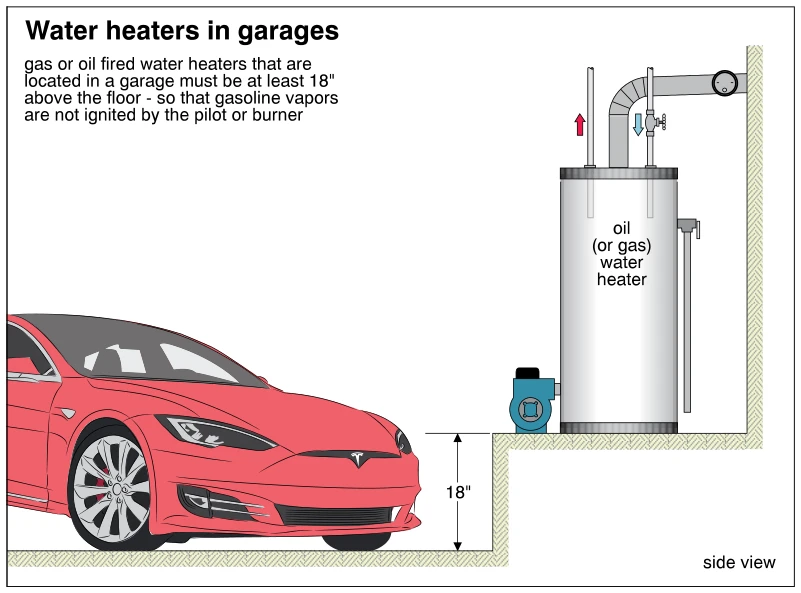 1872
1872Water heaters in garages
· p. 337
A side-view illustration shows a garage water heater on a raised platform beside a parked car. The platform is dimensioned 18 inches above the garage floor, elevating the heater and its burner. The heater has water piping above the tank, a vent that turns toward the adjacent wall, and a side-mounted valve with a downward discharge pipe. The annotation explains that elevating gas- or oil-fired water heaters helps prevent gasoline vapors from being ignited by the pilot or burner.
Exterior Structures ·Basement Walkoutsp. 338
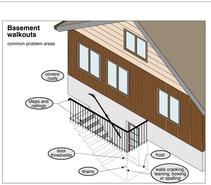 1873
1873Basement walkouts
· p. 338
The illustration shows an exterior basement walkout with stairs descending alongside the house to a below-grade door and landing. Railings surround the open stairwell, and a wall-mounted handrail follows the stair slope. Dashed outlines reveal the below-grade stairwell walls and landing, including a drain near the bottom. Callouts identify common inspection problem areas: covers or roofs, steps and railings, door thresholds, drains, frost, and stairwell walls. Wall cracking, leaning, bowing, and spalling are listed as potential concerns rather than illustrated in detail.
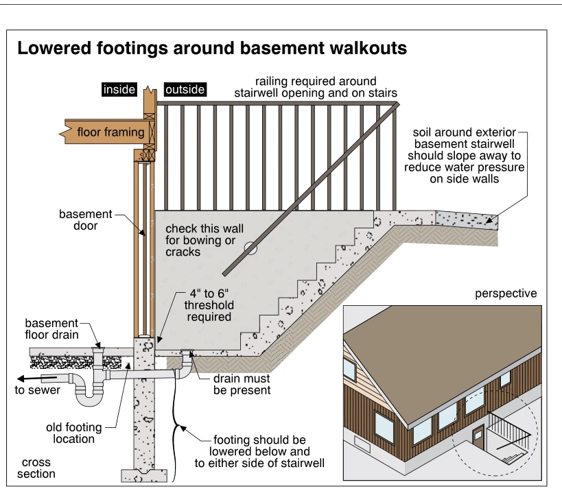 1874
1874Lowered footings around basement walkouts
· p. 338
The illustration shows a cross section of an exterior basement walkout stairwell, with a perspective inset locating it beside a house. The foundation footing is lowered below the stairwell and is noted to extend to either side, with the old footing location identified near basement floor level. Concrete stairs descend to a landing with a drain connected to the illustrated sewer drainage piping, and a 4-inch to 6-inch threshold is specified at the basement door. Railings protect the stairwell opening and stairs, while surrounding soil is directed to slope away to reduce water pressure on the side walls. An annotation instructs inspectors to check the stairwell wall for bowing or cracks.
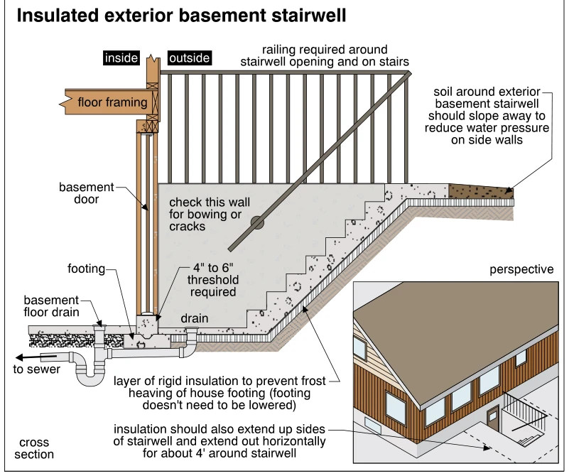 1875
1875Insulated exterior basement stairwell
· p. 338
A cross section shows an exterior basement stairwell descending to a basement door beside the house footing, with a perspective inset locating the walkout alongside the house. Rigid insulation extends beneath the stairwell, and an annotation calls for insulation up the sides and horizontally for about four feet around the stairwell to prevent frost heaving of the house footing. A drain at the bottom landing connects to piping leading toward the sewer, and the door has a specified four- to six-inch threshold. Railings protect the stairwell opening and stairs, while surrounding soil is directed to slope away to reduce water pressure on the side walls. An inspection callout directs attention to checking the stairwell wall for bowing or cracks; these defects are not actually illustrated.
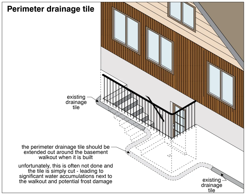 1876
1876Perimeter drainage tile
· p. 338
The illustration shows an exterior basement walkout with stairs descending alongside the house foundation to a basement door, enclosed by a metal guard railing. Dashed lines reveal the below-grade stairwell and the perimeter drainage tile routing around its outer footprint. The proposed drainage route connects the existing drainage tile on either side of the walkout rather than passing through the excavation. An annotation warns that simply cutting the existing tile without extending it around the walkout can cause significant water accumulation and potential frost damage.
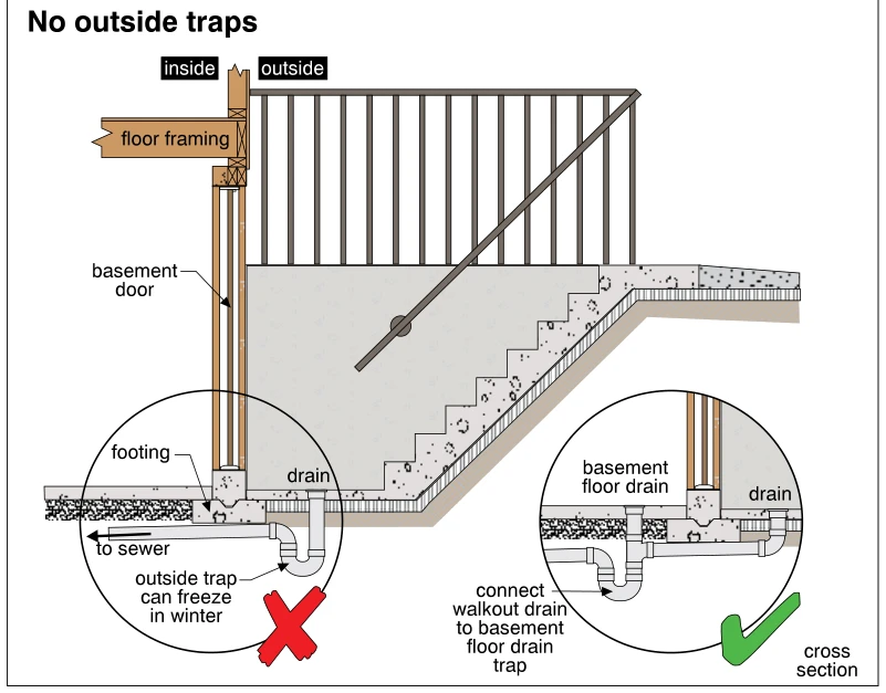 1877
1877No outside traps
· p. 338
The cross section depicts an exterior basement walkout stairwell with a drain at the bottom landing adjacent to the basement door. Concrete stairs rise to an exterior landing, with a sloped handrail and an upper guard. A circular detail marked with a red X shows an exterior drain trap and warns that it can freeze in winter. A second detail marked with a green check shows the walkout drain connected to the basement floor drain trap inside the building instead.
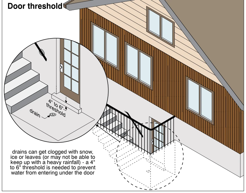 1878
1878Door threshold
· p. 338
The illustration shows an exterior basement stairwell alongside a house, with stairs descending to a basement entrance and a guardrail surrounding the opening. An enlarged detail shows the stairwell landing, a floor drain, and a raised threshold at the door. The threshold is labeled as 4 to 6 inches high to prevent water from entering under the door. The annotation warns that drains can become clogged with snow, ice, or leaves, or may be unable to handle heavy rainfall.
Surface Water Control And Landscaping ·Lot Gradingp. 339
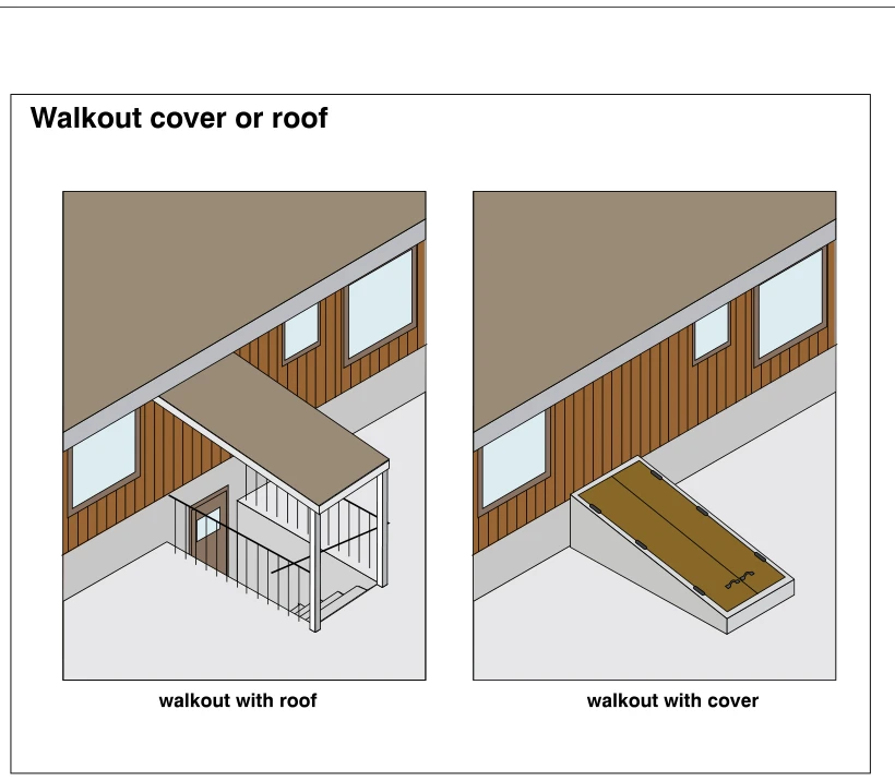 1879
1879Walkout cover or roof
· p. 339
The illustration shows two ways to shelter an exterior basement stairwell alongside a house. On the left, a roof extends from the house over the stairwell and is supported by posts at its outer edge. Railings surround the open stairwell, which descends to a basement entrance door. On the right, a pair of sloping hinged covers closes over the stairwell opening on raised sidewalls. The two arrangements are presented as alternatives, with no defects identified.
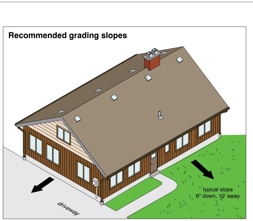 1880
1880Recommended grading slopes
· p. 339
The illustration shows a house bordered by a paved driveway, a curved entrance walkway, and lawn. Large arrows on the driveway and lawn indicate surface drainage away from the building. The lawn annotation specifies a typical grading slope of 6 inches down over 10 feet away from the house. Gutters and downspouts are visible along the roof edges and exterior corners. The figure depicts recommended positive grading around the foundation rather than a defective condition.
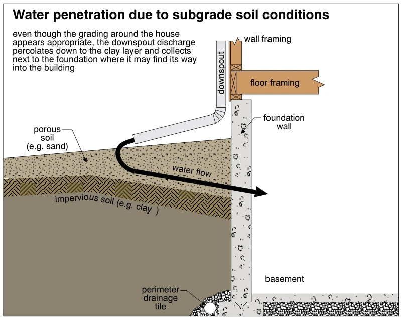 1881
1881Water penetration due to subgrade soil conditions
· p. 339
The cross-section shows a basement foundation wall, footing, floor slab, perimeter drainage tile, and wood wall and floor framing above. A downspout discharges onto porous soil at a surface that slopes away from the house. Beneath the porous soil, an impervious clay layer slopes toward the foundation. A heavy arrow shows discharge water percolating downward, following this buried layer toward the wall, and penetrating into the basement despite apparently appropriate surface grading.
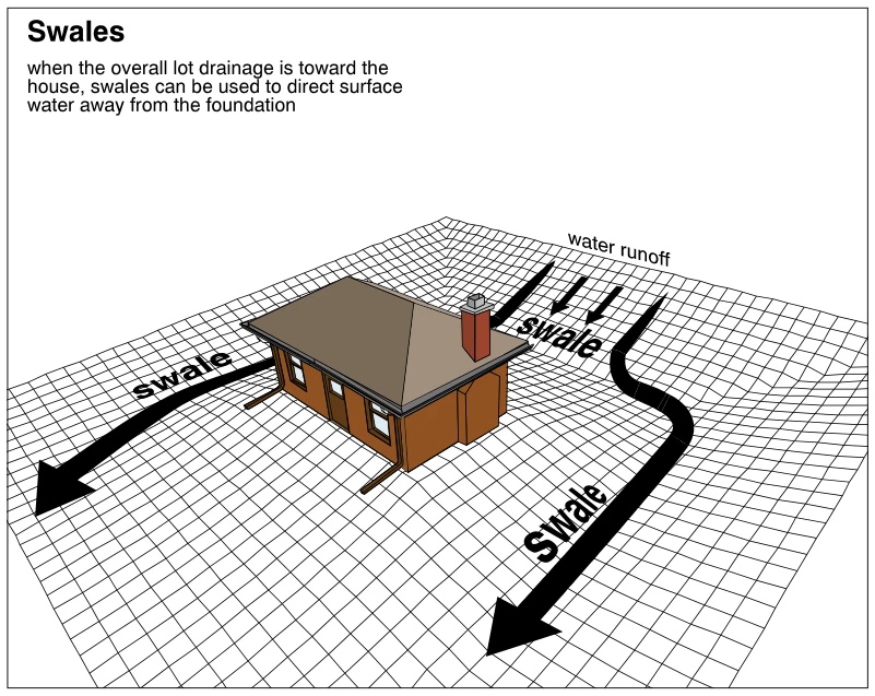 1882
1882Swales
· p. 339
The illustration shows a house on a sloping lot, with a gridded ground surface indicating the surrounding contours. Arrows show surface runoff moving downhill toward the house from higher ground behind it. Shallow drainage swales intercept and divert this runoff around both sides of the house toward lower ground. Large arrows trace the drainage paths away from the foundation, illustrating proper use of swales where the overall lot slope directs water toward the building.
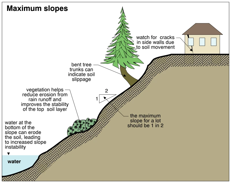 1883
1883Maximum slopes
· p. 339
The illustration shows a cross-section of a sloping lot with a house on level ground at the top and water at the toe of the slope. A slope triangle identifies a maximum lot slope of one vertical to two horizontal. Shrubs illustrate vegetation's role in reducing runoff erosion and stabilizing the topsoil. A bent tree trunk is identified as a possible sign of soil slippage, and an arrow at the house advises checking side walls for cracks caused by soil movement. Water at the bottom is identified as a potential source of soil erosion and increased slope instability.
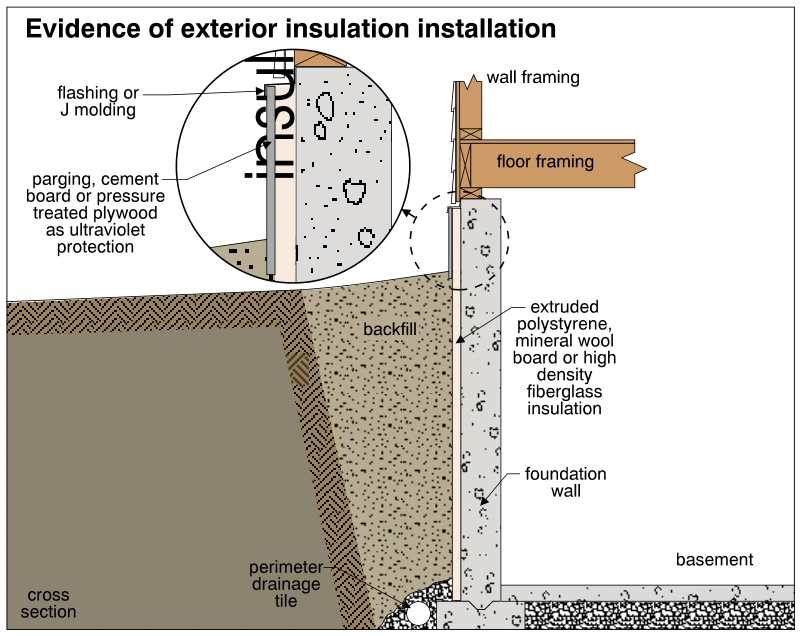 1884
1884Evidence of exterior insulation installation
· p. 339
The cross section shows exterior insulation extending down a foundation wall from the wood-framed wall above to the footing area. Backfill lies against the insulated foundation, with the ground surface sloping away from the building. A magnified detail shows flashing or J molding at the insulation's upper edge and an exterior protective covering identified as parging, cement board, or pressure treated plywood for ultraviolet protection. A perimeter drainage tile sits beside the footing, and the basement floor extends inward from the foundation wall.
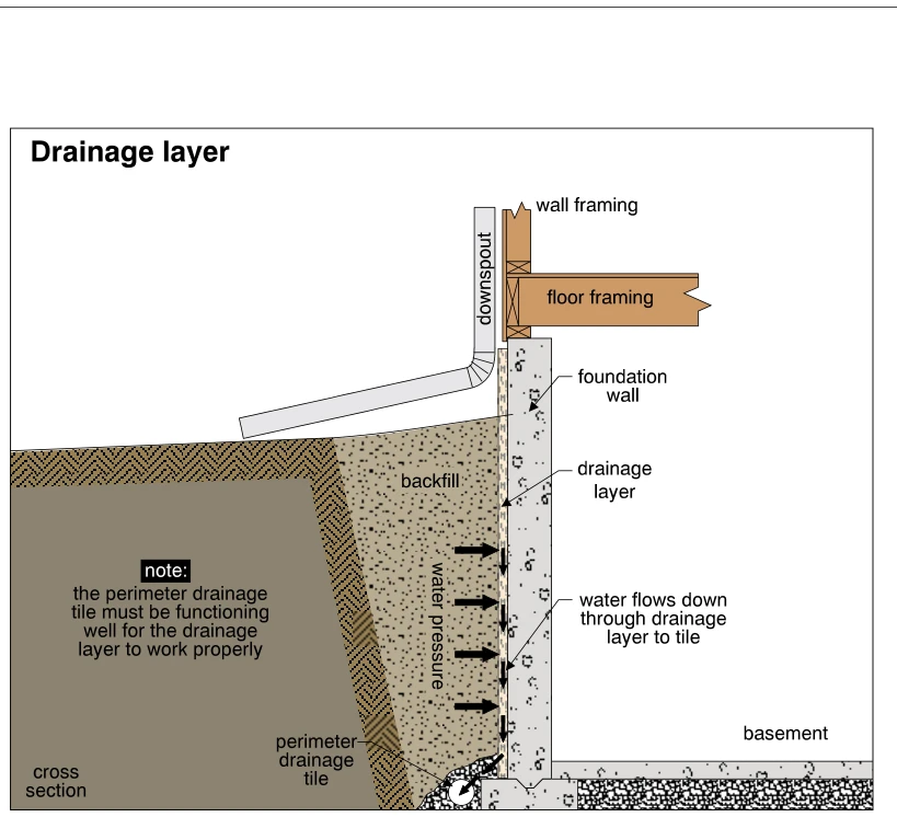 1885
1885Drainage layer
· p. 340
The cross section shows a drainage layer against the exterior face of a foundation wall, between the wall and the backfill. Horizontal arrows indicate water pressure from the backfill, while downward arrows show water moving through the drainage layer to the perimeter drainage tile beside the footing. A note states that the perimeter drainage tile must function well for the drainage layer to work properly. Above grade, a downspout extension directs roof runoff away from the foundation, and wood wall and floor framing rest above the foundation wall. The basement slab and its granular base are shown on the interior side.
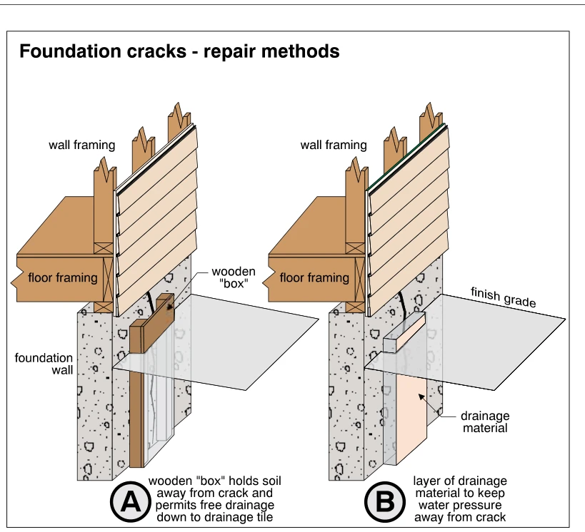 1886
1886Foundation cracks - repair methods
· p. 340
Two cutaway views show exterior drainage treatments at cracks in concrete foundation walls beneath wood-framed walls and horizontal siding. Method A places a vertical wooden box against the foundation over the crack, holding soil away and allowing water to drain down toward drainage tile, as described in the annotation. Method B places a vertical layer of drainage material against the cracked area to keep water pressure away from the crack. Both treatments extend below the illustrated grade plane, with their upper ends exposed above it.
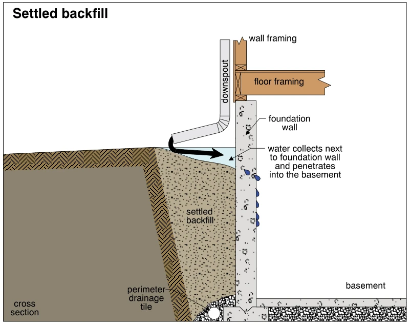 1887
1887Settled backfill
· p. 340
The cross section shows settled backfill beside a basement foundation wall, creating a ground surface that slopes toward the house. A downspout discharges onto this depressed area, and an arrow shows water flowing toward the foundation. Water collects against the wall and is depicted penetrating into the basement. Wall and floor framing sit above the foundation, while perimeter drainage tile is shown near the base of the wall.
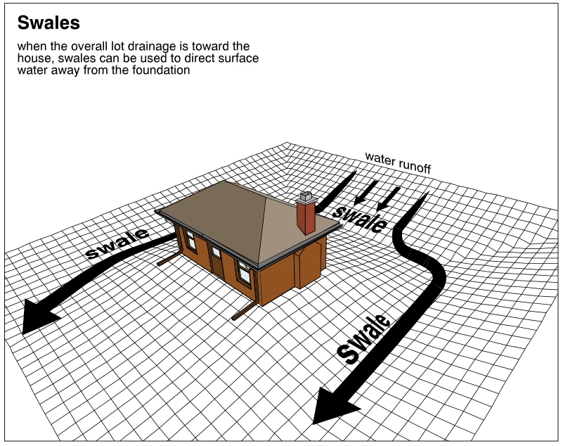 1888
1888Swales
· p. 340
The illustration shows a house on a sloping lot represented by a contoured grid. Arrows indicate surface water running downhill toward the house from the higher ground behind it. Swales intercept this runoff and route it around both sides of the house toward lower ground. The diagram illustrates using graded drainage channels to direct surface water away from the foundation.
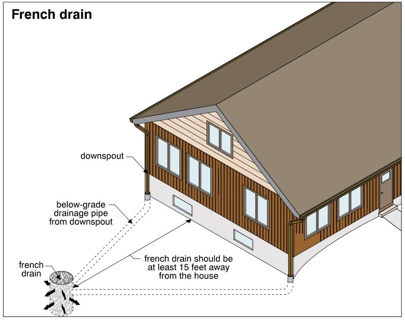 1889
1889French drain
· p. 340
The illustration shows a house with roof-edge gutters and downspouts connected to below-grade drainage pipes. Dashed lines trace the buried pipes from two corners of the house to a stone-filled French drain away from the foundation. Arrows around the drain indicate water dispersing into the surrounding ground. An annotation specifies that the French drain should be at least 15 feet away from the house.
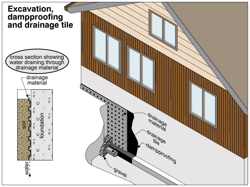 1890
1890Excavation, dampproofing and drainage tile
· p. 340
The illustration shows an excavated area beside a house foundation, exposing exterior dampproofing, a drainage layer, and drainage tile at the base of the wall. A cutaway reveals the drainage material over the black dampproofing coating, with gravel surrounding part of the drainage tile. An inset cross section shows soil separated from the foundation by drainage material, with an arrow indicating downward water movement. The assembly illustrates foundation moisture management without depicting a specific defect.
Surface Water Control And Landscaping ·Gutters and Downspoutsp. 341
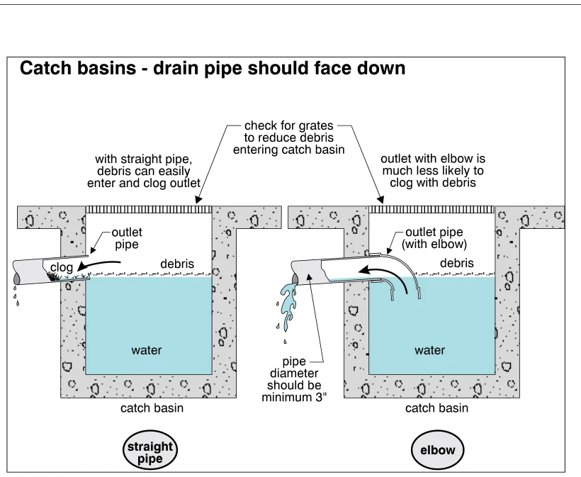 1891
1891Catch basins - drain pipe should face down
· p. 341
Two cross-sections compare catch basin outlet configurations beneath surface grates. The left basin has a straight outlet pipe at the water surface, where floating debris enters and clogs the outlet, restricting discharge. The right basin has a downward-facing outlet elbow with its intake below the floating debris layer, allowing water to discharge with less likelihood of clogging. Annotations recommend checking for grates to reduce debris entry and specify a minimum pipe diameter of 3 inches.
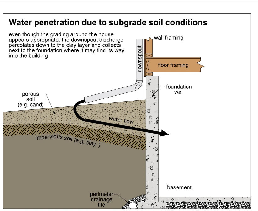 1892
1892Water penetration due to subgrade soil conditions
· p. 341
The illustration shows a section through a house foundation, basement, and adjacent soil, with a downspout discharging onto ground that slopes away from the building. A porous soil layer overlies an impervious layer that slopes toward the foundation. A water-flow arrow traces downspout discharge percolating through the porous soil and moving toward and through the foundation wall. Wall and floor framing are shown above the foundation, with perimeter drainage tile beside the footing. The diagram illustrates how subsurface soil conditions can direct water into a basement despite apparently appropriate surface grading.
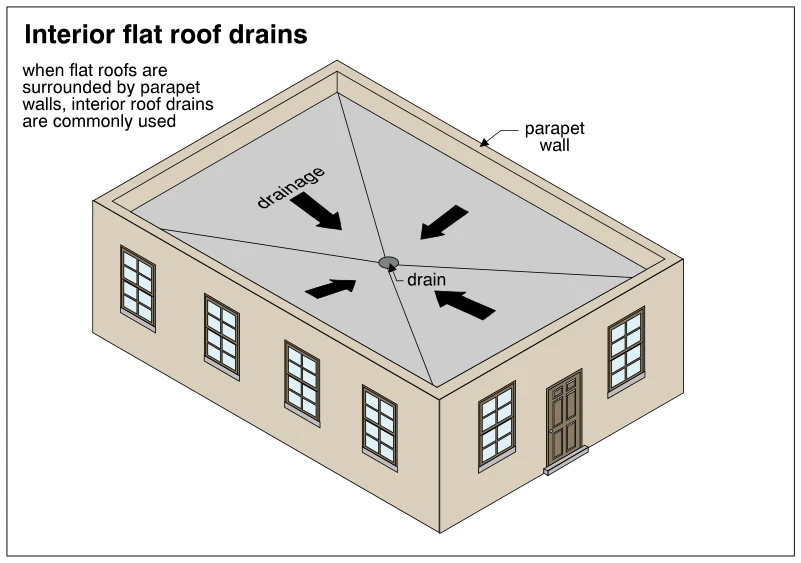 1893
1893Interior flat roof drains
· p. 341
The illustration shows a rectangular building with a flat roof enclosed by parapet walls. Roof planes converge toward a centrally located interior roof drain. Large arrows indicate drainage toward the drain from surrounding roof areas. The drawing explains the use of interior drains on roofs bounded by parapets; no interior piping or drainage defects are shown.
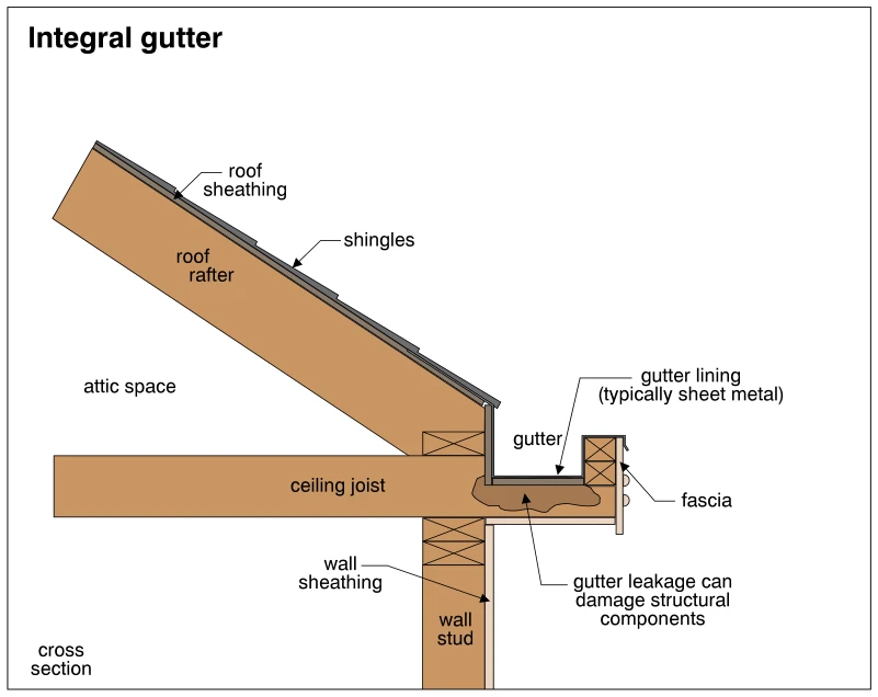 1894
1894Integral gutter
· p. 341
The illustration shows a cross section of an integral gutter built into the eave of a sloping shingle roof. The gutter lining extends down from the roof edge and across a recessed trough behind the fascia. Roof rafters, a ceiling joist, and a wall stud with wall sheathing show how the gutter relates to the surrounding wood framing. A marked area beneath the gutter illustrates the warning that gutter leakage can damage structural components.
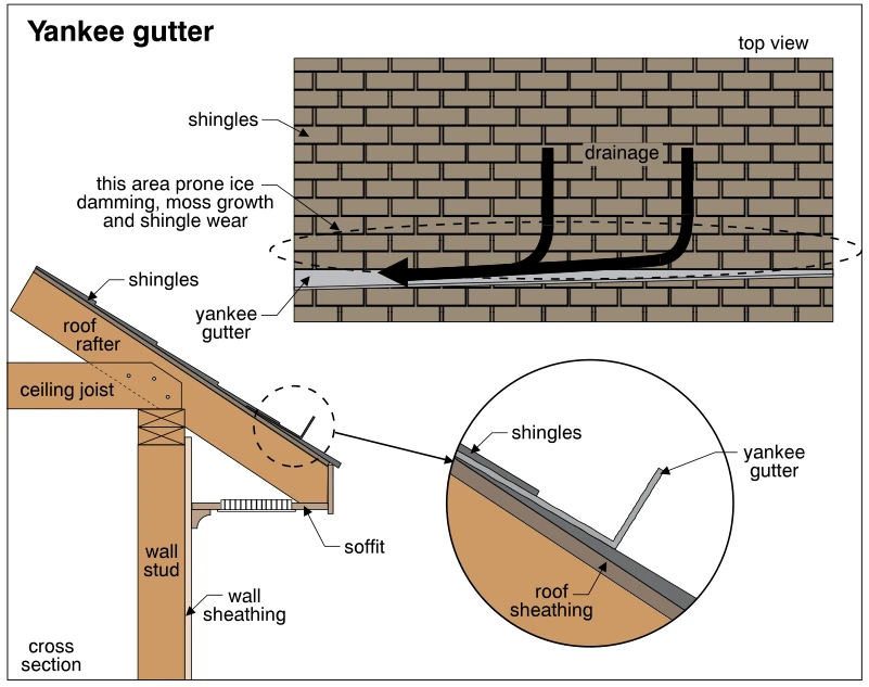 1895
1895Yankee gutter
· p. 341
The illustration shows a Yankee gutter installed on a shingled roof above the eave, using a top view, an eave cross section, and an enlarged detail. The detail shows a sheet-metal gutter profile extending beneath the shingles and turning upward to intercept runoff on the roof slope. Arrows in the top view show water flowing down the shingles and then laterally along the gutter. A dashed outline identifies the roof area immediately upslope of the gutter as prone to ice damming, moss growth, and shingle wear. The cross section also shows the roof rafter, roof sheathing, ceiling joist, wall framing, wall sheathing, and soffit.
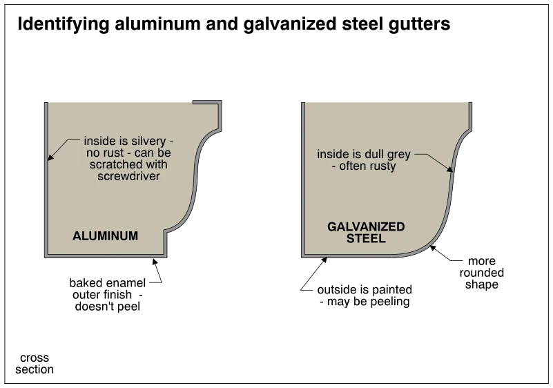 1896
1896Identifying aluminum and galvanized steel gutters
· p. 341
The illustration compares cross sections of aluminum and galvanized steel gutters. The aluminum gutter has a more angular bottom-to-front transition and is identified by a silvery interior that does not rust and can be scratched with a screwdriver. Its exterior is labeled as a baked enamel finish that does not peel. The galvanized steel gutter has a more rounded lower front profile, a dull grey interior described as often rusty, and a painted exterior that may peel. These are material-identification comparisons rather than examples of proper and improper installation.
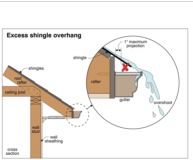 1897
1897Excess shingle overhang
· p. 342
The illustration shows a cross section of a roof eave and exterior wall, with an enlarged detail of the shingle edge and gutter. The section identifies the roof rafter, ceiling joist, wall stud, and wall sheathing. In the enlarged detail, the shingles extend excessively beyond the roof edge over the gutter, marked with a red X. Water running off the extended shingles overshoots the gutter's outer rim rather than being collected. A dimension annotation specifies a 1-inch maximum projection.
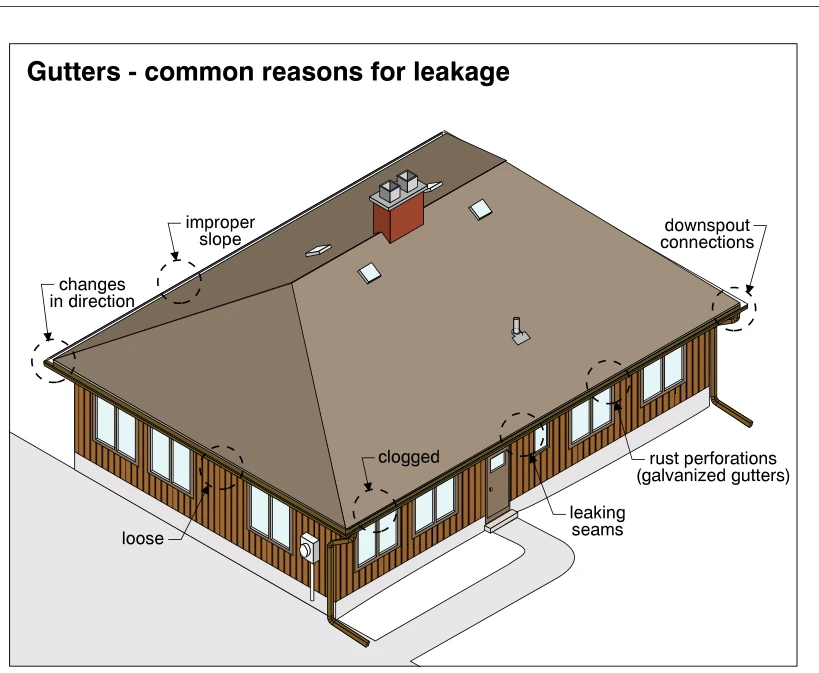 1898
1898Gutters - common reasons for leakage
· p. 342
An oblique view of a house shows gutters along the roof eaves and downspouts descending at exterior corners. Dashed circles and arrows identify common gutter leakage locations and conditions, including changes in direction, downspout connections, and leaking seams. Other callouts identify improper gutter slope, clogging, and loose gutters. Rust perforations are specifically associated with galvanized gutters.
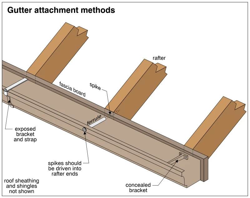 1900
1900Gutter attachment methods
· p. 342
The illustration shows an open gutter mounted along a fascia board in front of exposed rafter ends. Three attachment methods are depicted: an exposed bracket and strap, a spike with a ferrule, and a concealed bracket. The ferrule spans the gutter to support the spike attachment, and an annotation specifies that spikes should be driven into rafter ends. The concealed bracket fits inside the gutter and connects it to the fascia. Roof sheathing and shingles are explicitly omitted to reveal the attachment details.
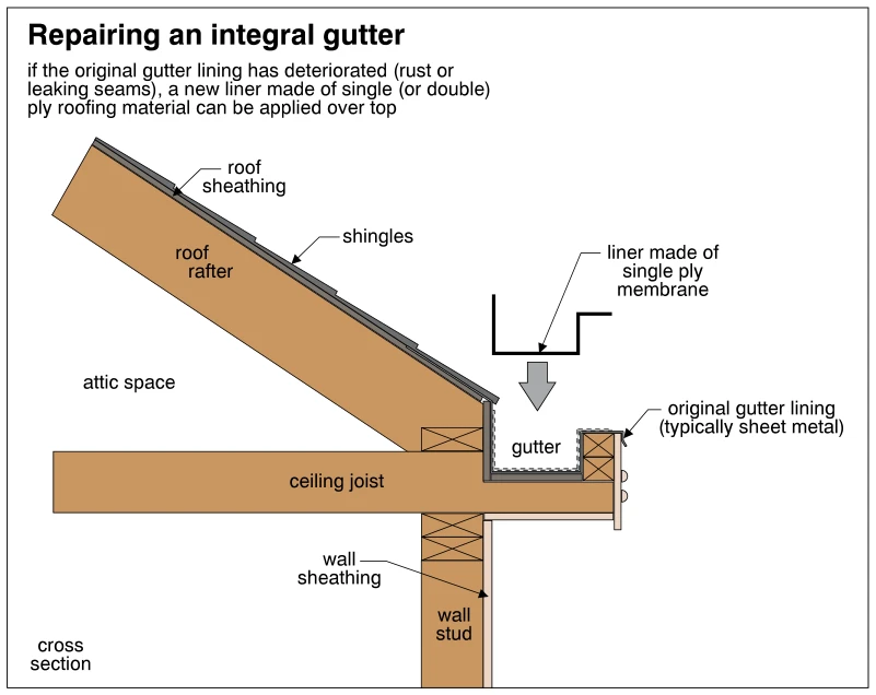 1899
1899Repairing an integral gutter
· p. 342
A cross section shows an integral gutter built into the eave of a sloped shingle roof. The gutter sits above the projecting ceiling joist, beside the roof rafter and exterior wall framing. The original gutter lining, identified as typically sheet metal, follows the recessed gutter channel. A separate single-ply membrane liner is shown above the channel with a downward arrow indicating placement over the existing lining. The annotation describes this as a repair for an original lining deteriorated by rust or leaking seams and allows single- or double-ply roofing material.
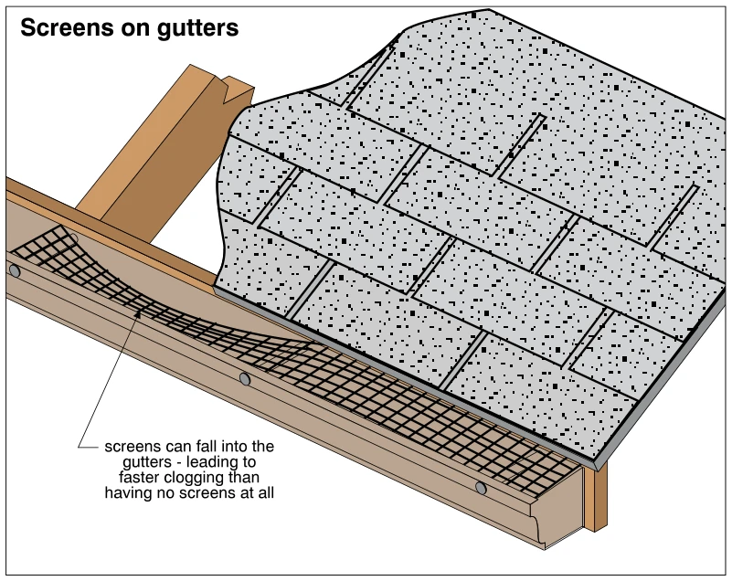 1901
1901Screens on gutters
· p. 342
The illustration shows a screened eaves gutter below a sloped shingle roof, with wood framing exposed at the cutaway. Mesh screening spans the gutter opening, but a section has sagged or fallen into the trough. The annotation warns that fallen screens can cause gutters to clog faster than gutters with no screens. No downspout is visible.
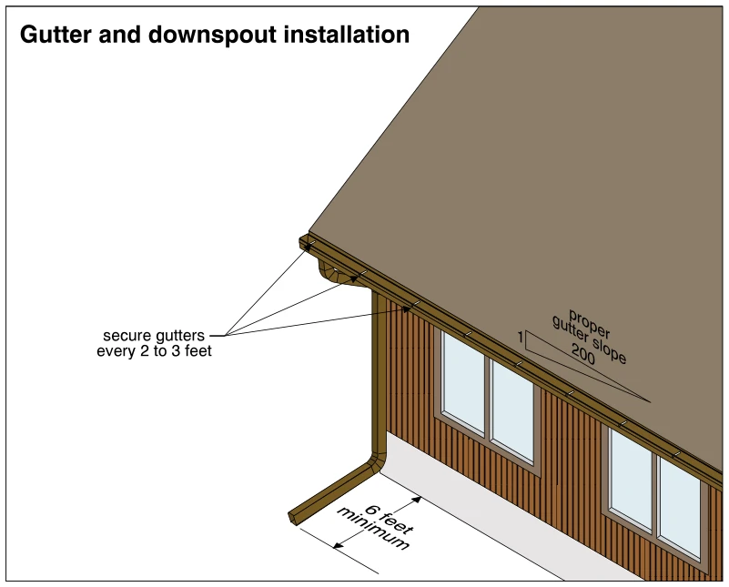 1902
1902Gutter and downspout installation
· p. 342
The illustration shows an eaves gutter along a sloped roof, connected to a downspout running down the exterior wall. Callouts specify securing the gutter every 2 to 3 feet and providing a proper gutter slope of 1 in 200. The downspout turns outward near the base of the wall and connects to an extension that discharges away from the building. A dimension indicates a minimum discharge distance of 6 feet from the wall. This depicts proper gutter support, drainage slope, and downspout discharge placement.
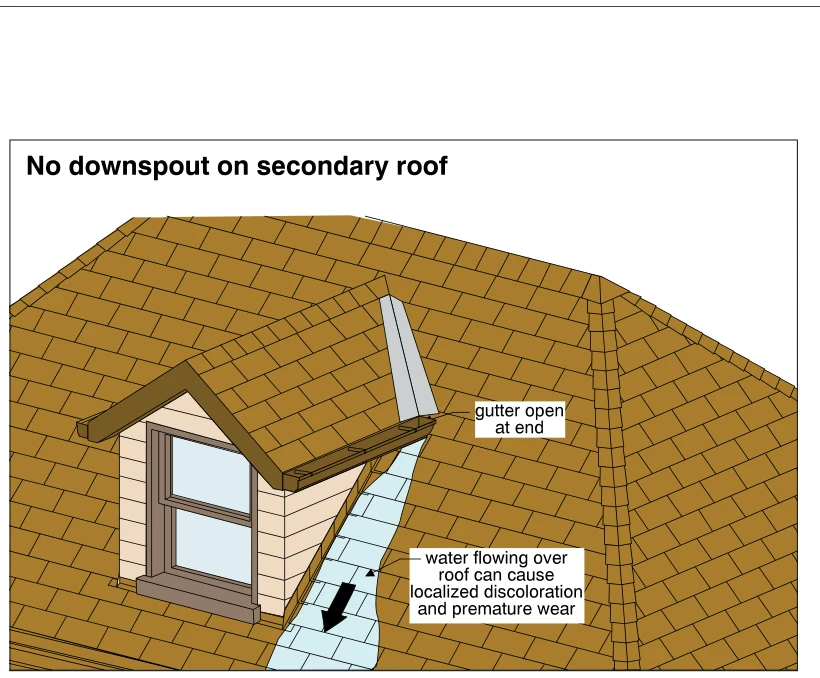 1903
1903No downspout on secondary roof
· p. 343
The illustration shows a gabled dormer projecting from a larger shingled roof. A gutter along the dormer roof eave is open at its end and has no downspout. Water discharges from this gutter directly onto the main roof, with a highlighted flow path and arrow showing runoff traveling downslope. The annotation identifies localized discoloration and premature wear as potential consequences of this concentrated roof runoff.
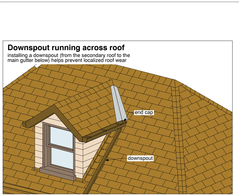 1904
1904Downspout running across roof
· p. 343
The illustration shows a gabled dormer projecting from a larger shingled roof. A gutter along the dormer eave has a labeled end cap and connects to a downspout running down the main roof slope toward the gutter below. Exposed valley flashing is visible where the dormer roof meets the main roof. The annotation recommends carrying runoff from the secondary roof to the main gutter through a downspout to prevent localized roof wear.
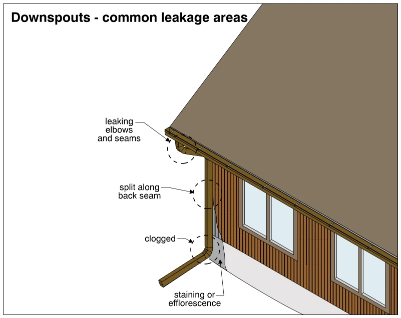 1906
1906Downspouts - common leakage areas
· p. 343
The illustration shows an eaves gutter connected to a downspout on the exterior of a house with vertical siding and windows. The downspout descends along the wall and turns through a lower elbow into an extension that discharges away from the building. Dashed circles and arrows identify leaking elbows and seams near the gutter connection, a split along the back seam of the vertical downspout, and a clog at the lower elbow. Staining or efflorescence is indicated on the exposed foundation wall beside the lower downspout.
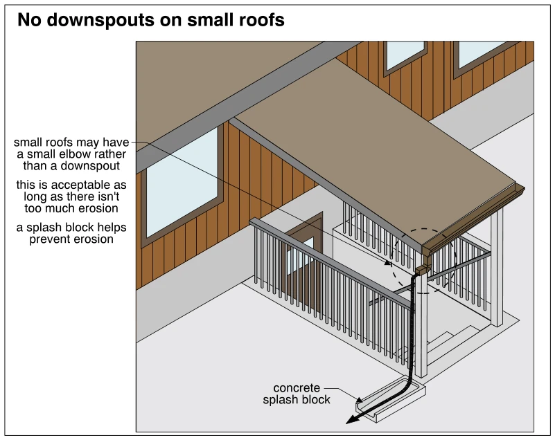 1905
1905No downspouts on small roofs
· p. 343
The illustration shows a small sloped roof covering an entrance porch, with a gutter along its lower edge. A short outlet elbow at the gutter end is highlighted as an alternative to a full-height downspout. The annotations state that this arrangement is acceptable provided it does not cause excessive erosion. A full-height downspout route is also illustrated beside the porch post, discharging onto a concrete splash block with an arrow indicating flow away from the porch.
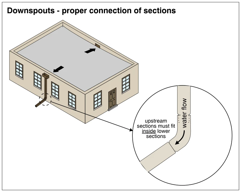 1907
1907Downspouts - proper connection of sections
· p. 343
The illustration shows a flat-roofed building with parapet walls and an exterior downspout discharging through an elbow and angled extension near grade. Arrows on the roof indicate drainage toward openings at the roof perimeter. An enlarged detail shows how the vertical downspout, elbow, and downstream extension overlap. Upstream sections fit inside lower sections so water flows through the joints in the direction of the overlap rather than into an exposed upstream-facing seam.
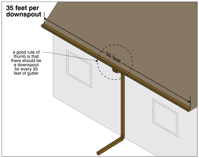 1908
190835 feet per downspout
· p. 343
The illustration shows an eaves gutter along a sloping roof edge draining into a single downspout near the middle of the wall. A dimension line marks 35 feet of gutter, and an annotation recommends one downspout for every 35 feet of gutter as a rule of thumb. An offset connects the gutter outlet to the vertical downspout against the exterior wall. At the bottom, an elbow and extension direct discharge away from the wall.
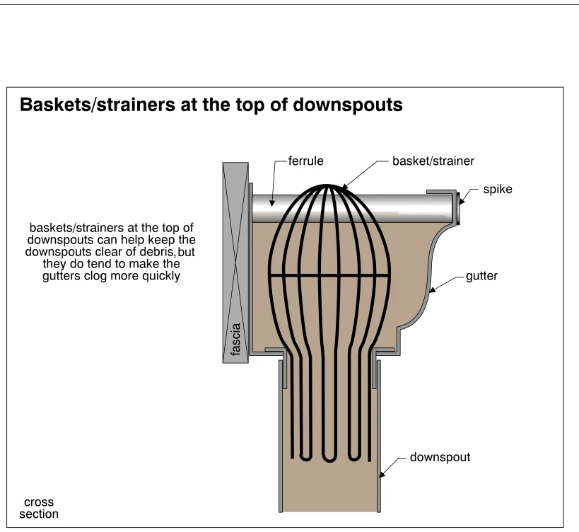 1909
1909Baskets/strainers at the top of downspouts
· p. 344
The cross section shows a gutter mounted against a fascia with a spike and ferrule, and a downspout connected beneath the gutter outlet. An open-wire basket/strainer sits over the outlet, with its bulbous upper portion projecting into the gutter and its narrow lower portion extending into the downspout. The strainer intercepts debris before it enters the downspout. The annotation explains that these strainers help keep downspouts clear but tend to make gutters clog more quickly; no actual debris blockage is drawn.
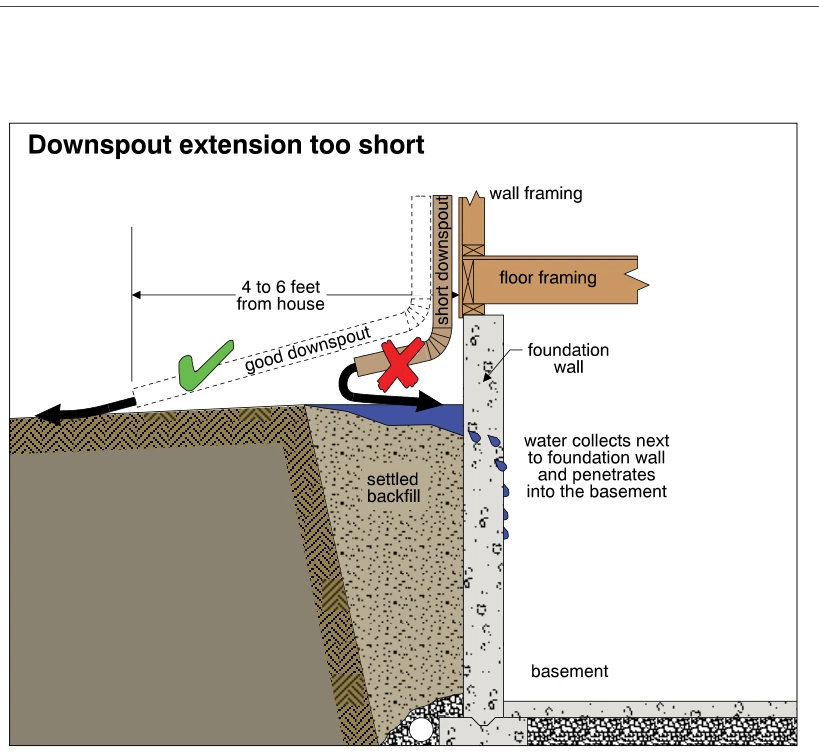 1910
1910Downspout extension too short
· p. 344
A cross-section at a house foundation compares a short downspout outlet with a longer extension shown in dashed outline. The short outlet, marked with a red X, discharges into a depression in settled backfill beside the foundation wall. Arrows show runoff collecting at the wall, and blue droplets depict water penetrating into the basement. The longer extension, marked with a green check, directs water away from the house to a discharge point labeled 4 to 6 feet from the house. Wall and floor framing, the foundation wall and footing, and the basement floor are also shown.
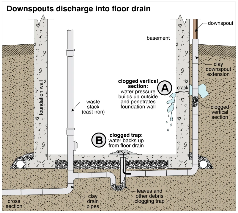 1911
1911Downspouts discharge into floor drain
· p. 344
This cross section shows an exterior downspout connected to a clay extension that descends alongside a basement foundation and runs beneath the floor to the floor-drain piping. The underfloor clay drainage system also connects to a cast-iron waste stack. Condition A shows a clogged vertical downspout extension, with water accumulating outside the foundation and penetrating a crack into the basement. Condition B shows leaves and other debris clogging the floor-drain trap, causing water to back up through the floor drain onto the basement floor.
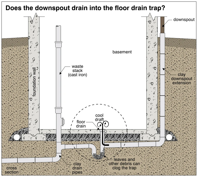 1912
1912Does the downspout drain into the floor drain trap?
· p. 344
A cross section through a basement shows an exterior downspout connected to a buried clay extension beside the foundation wall. The extension turns beneath the basement floor and connects to the floor drain above its trap. The trapped drain connects to clay drain piping that also receives discharge from a cast-iron waste stack. Arrows at the floor drain indicate a cool draft, and debris is shown collecting in the trap. The illustration highlights the risk of leaves and other downspout debris clogging the floor drain trap.
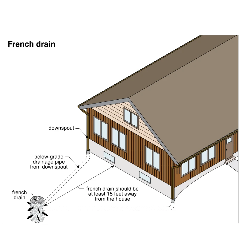 1913
1913French drain
· p. 345
The illustration shows roof-edge gutters and downspouts on a house conveying runoff into below-grade drainage pipes. Dashed lines trace the underground pipes from two downspouts to a cylindrical, stone-filled French drain away from the foundation. Arrows around the drain indicate water dispersing into the surrounding ground. A dimension annotation specifies that the French drain should be at least 15 feet away from the house.
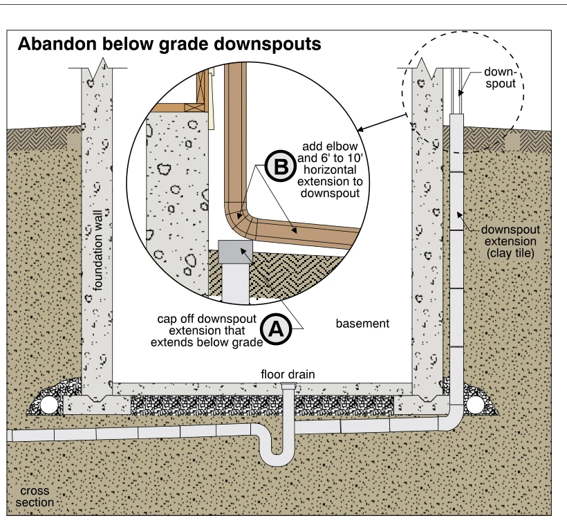 1914
1914Abandon below grade downspouts
· p. 345
A cross section through a basement shows a downspout connected to a clay-tile extension running below grade alongside the foundation wall and into piping beneath the basement. A floor drain and drainage pipes beside the foundation footings are also shown. An enlarged detail illustrates abandoning the below-grade downspout connection by capping the underground extension. The downspout is redirected through an elbow into a 6- to 10-foot horizontal extension above grade, carrying roof runoff away from the foundation.
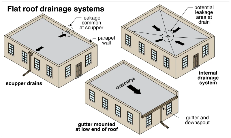 1915
1915Flat roof drainage systems
· p. 345
The illustration shows three drainage arrangements for flat roofs. The scupper arrangement directs water through openings in a parapet wall, with an exterior downspout shown and a note identifying scuppers as common leakage locations. The internal drainage arrangement shows roof surfaces sloping toward a central roof drain, identified as a potential leakage area. The third arrangement directs water toward an open low roof edge equipped with a gutter and exterior downspout. Arrows indicate the direction of roof runoff.
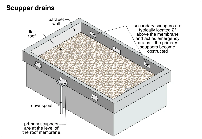 1916
1916Scupper drains
· p. 345
The illustration shows a flat roof enclosed by parapet walls with rectangular scupper openings through the walls. Primary scuppers are positioned at the level of the roof membrane, and one is shown discharging into an exterior collector connected to a downspout. Secondary scuppers are positioned higher in the parapet walls. The annotation specifies that these are typically 2 inches above the membrane and provide emergency drainage if the primary scuppers become obstructed.
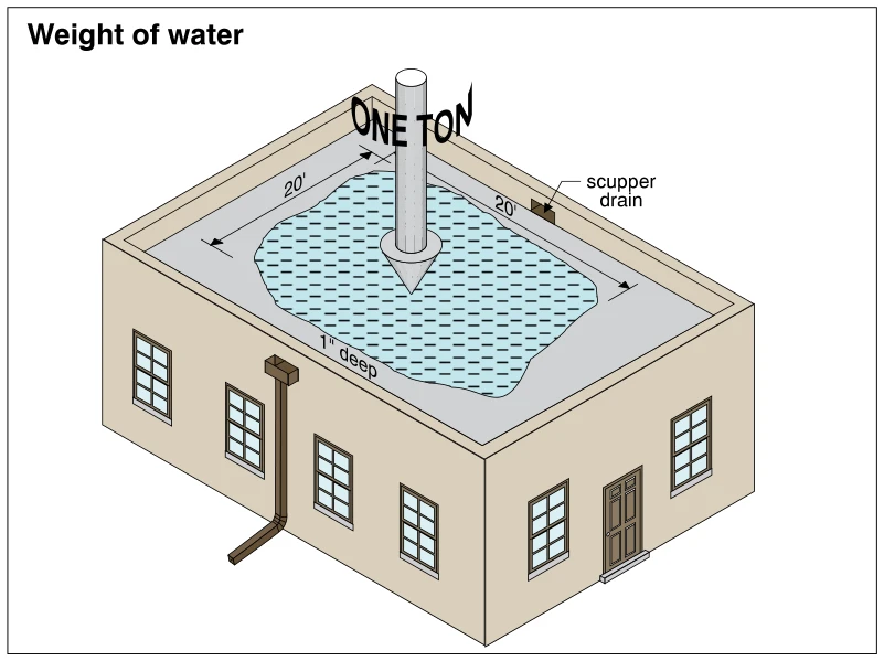 1917
1917Weight of water
· p. 345
The illustration shows a flat-roofed building with parapet walls and standing water on the roof. Dimension arrows indicate a 20-foot by 20-foot area, and the water is labeled as 1 inch deep. A large downward arrow labeled "ONE TON" emphasizes the load imposed by this accumulated water. A scupper drain is shown through a parapet, and an exterior downspout with a collection head and discharge elbow is visible on the building wall.
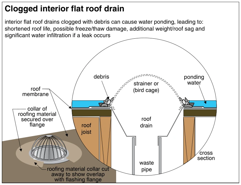 1918
1918Clogged interior flat roof drain
· p. 345
The illustration shows an interior flat-roof drain in perspective and an enlarged cross section. A domed bird-cage strainer covers the drain, which connects to a vertical waste pipe below the roof. The roofing membrane collar overlaps the drain flashing flange, with a cutaway exposing this connection. Debris accumulated around the base of the strainer obstructs drainage, leaving ponding water on the roof membrane. The annotation identifies potential consequences including shortened roof life, freeze/thaw damage, additional weight and roof sag, and significant water infiltration if a leak occurs.
Surface Water Control And Landscaping ·Window Wellsp. 346
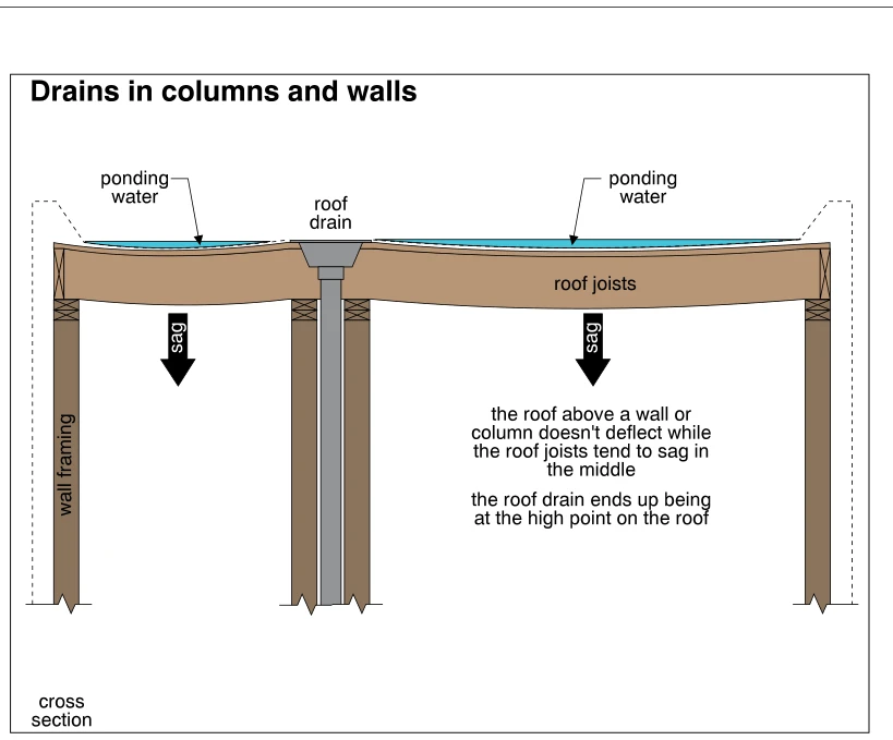 1919
1919Drains in columns and walls
· p. 346
The cross section shows roof joists spanning between exterior walls and a central wall or column containing a vertical roof drainage pipe. The roof drain is located directly above the central support, where the roof does not deflect. The joists sag between supports, creating low areas that collect ponding water on both sides of the drain. The drain consequently remains at a high point rather than draining the depressed roof areas.
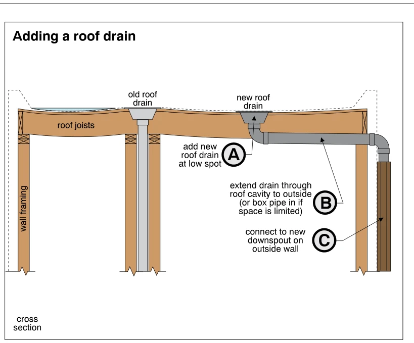 1920
1920Adding a roof drain
· p. 346
A cross section of a flat roof shows roof joists supported by wall framing, an existing roof drain, and a new drain at a roof low spot. The roof profile has depressions, with water shown collecting away from the old drain. The new drain connects through an elbow to a pipe extending through the roof cavity and out through the exterior wall. Outside, another elbow directs flow into a new downspout. The annotations present this as a drainage improvement and note that the pipe can be boxed in if space is limited.
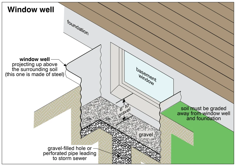 1921
1921Window well
· p. 346
A cutaway shows a steel window well surrounding a basement window in a foundation wall below exterior siding. The well projects above the surrounding soil and contains a gravel base, with a labeled 6-inch clearance from the window to the gravel. Beneath the well, a gravel-filled hole or perforated pipe provides a drainage path leading to a storm sewer. The surrounding soil is shown graded away from the window well and foundation.
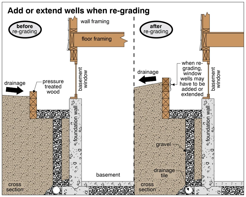 1922
1922Add or extend wells when re-grading
· p. 346
Two cross sections compare a basement window well before and after exterior re-grading. Before re-grading, the surface slopes toward the well, with an arrow indicating drainage toward the foundation. After re-grading, the raised surface slopes away from the house, and the pressure-treated wood well wall is extended above the new grade to retain soil clear of the basement window. Gravel beneath the well connects downward to drainage tile beside the foundation footing. The illustration emphasizes that window wells may need to be added or extended when changing exterior grades.
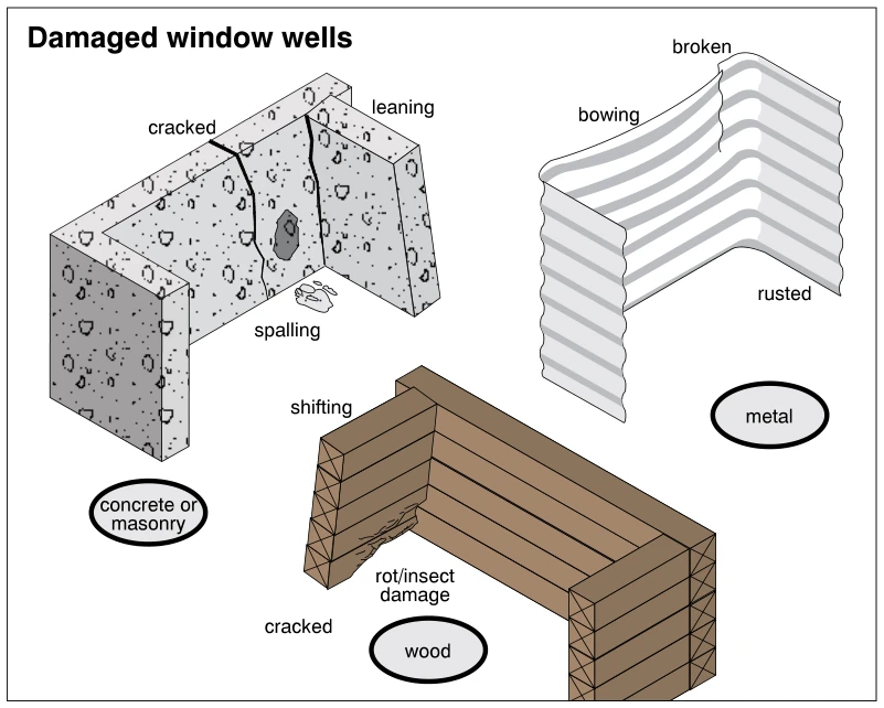 1923
1923Damaged window wells
· p. 346
The illustration shows three damaged, three-sided window wells made of concrete or masonry, corrugated metal, and stacked wood members. The concrete or masonry well has cracks, a leaning wall, and spalling with loose fragments at its base. The metal well is labeled as bowing, broken, and rusted, with a visible break near an upper corner. The wood well shows shifting members, cracking, and rot or insect damage near the bottom.
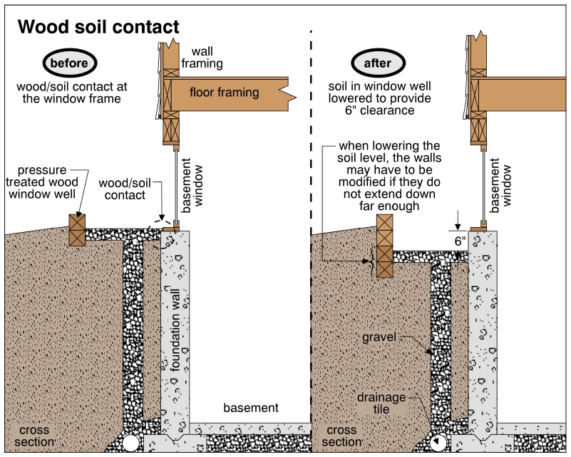 1924
1924Wood soil contact
· p. 346
Two cross sections compare a basement window well before and after correcting wood-to-soil contact at the window frame. The original condition shows the well surface at the bottom of the wood window frame, with a pressure-treated wood well wall retaining the surrounding soil. The corrected condition lowers the surface within the well to provide 6 inches of clearance below the frame. An annotation notes that the well walls may need modification if they do not extend down far enough for the lowered soil level. Gravel beneath the well connects to a vertical gravel-filled drainage path leading to drainage tile beside the foundation footing.
Surface Water Control And Landscaping ·Walks, Driveways and Groundsp. 347
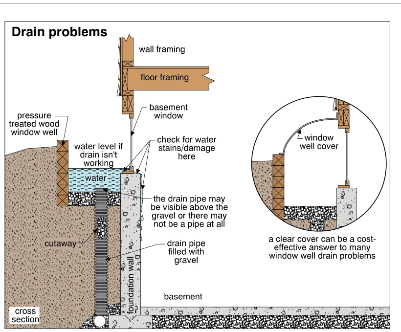 1925
1925Drain problems
· p. 347
A cross section shows a pressure-treated wood window well beside a basement window and foundation wall, with gravel at the bottom and a vertical drain pipe extending toward the footing drain. Standing water is illustrated rising to the window sill when the well drain is not working, and arrows identify areas to check for water stains or damage. A cutaway exposes gravel inside the drain pipe, while an annotation notes that the pipe may project above the gravel or may be absent altogether. An inset shows a curved clear window well cover presented as a cost-effective response to many window well drain problems.
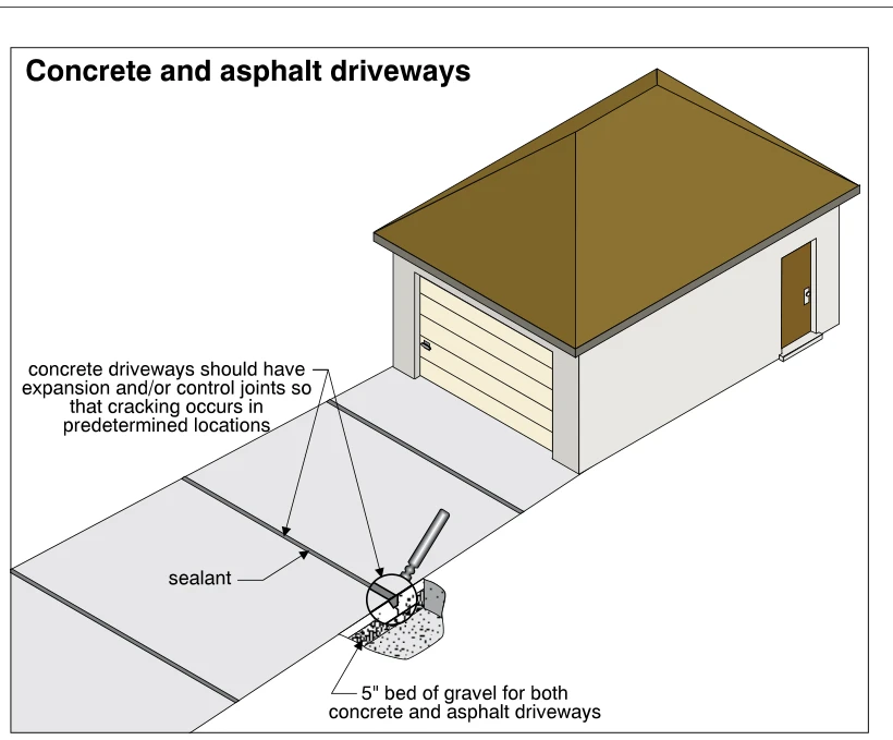 1926
1926Concrete and asphalt driveways
· p. 347
The illustration shows a driveway leading to a garage, with transverse joints dividing the concrete pavement into panels. An annotation explains that expansion and/or control joints locate cracking at predetermined positions. A sealant label and an applicator identify sealing at a joint. A cutaway at the driveway edge shows a 5-inch gravel bed, specified for both concrete and asphalt driveways.
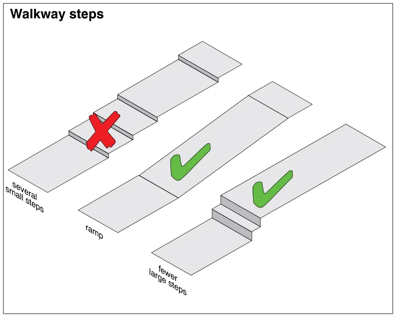 1927
1927Walkway steps
· p. 347
The illustration compares three ways to accommodate an elevation change in an exterior walkway. A walkway with several small, separated steps is marked with a red X, indicating an undesirable arrangement. A continuous ramp between walkway sections is marked with a green check. A third walkway with fewer, larger steps grouped together is also marked with a green check.
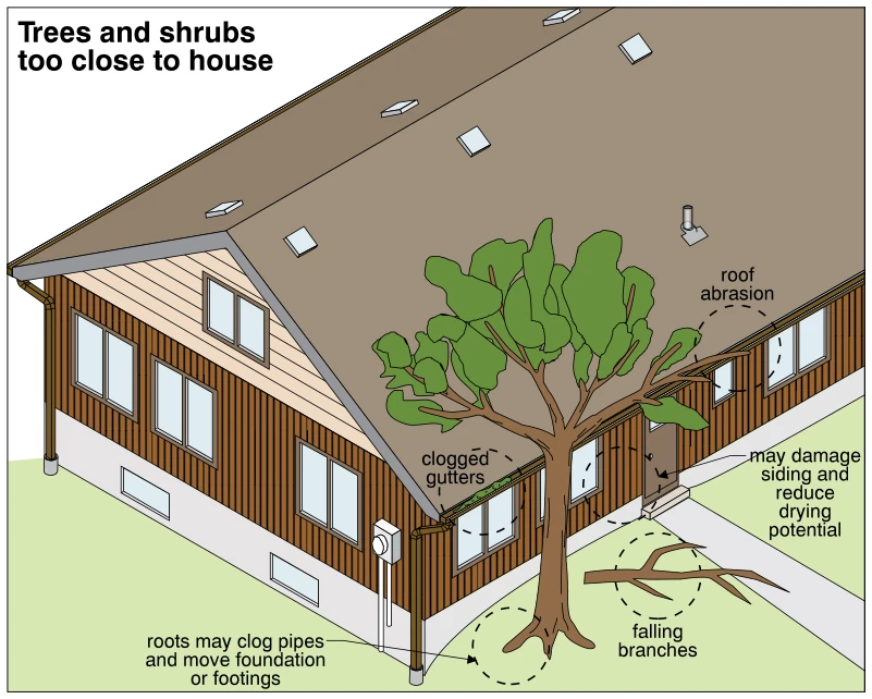 1928
1928Trees and shrubs too close to house
· p. 347
The illustration shows a large tree immediately beside a house, with branches extending over the roof and against the exterior walls. Callouts identify roof abrasion, clogged gutters, and potential siding damage and reduced drying where vegetation is too close. A fallen branch on the lawn illustrates the hazard of falling limbs. A callout near the tree base warns that roots may clog pipes and move the foundation or footings.
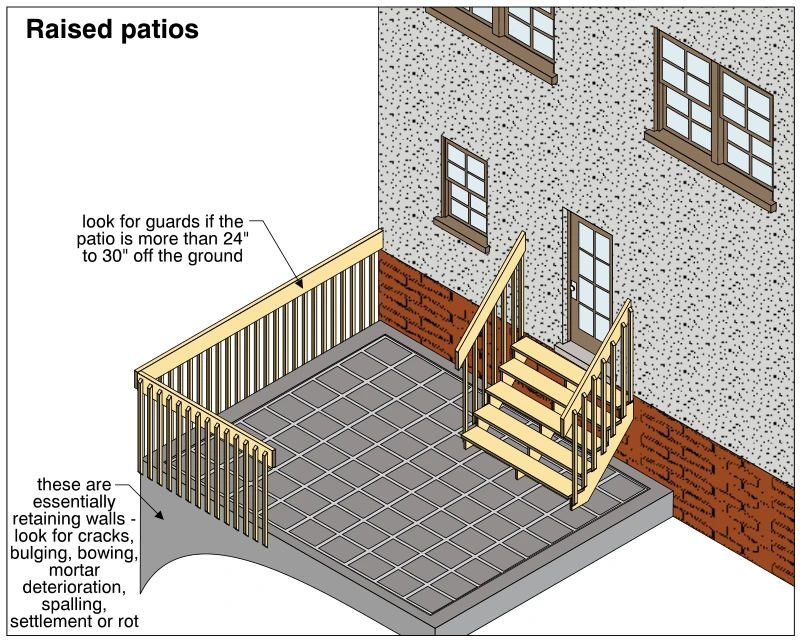 1929
1929Raised patios
· p. 347
The illustration shows a raised, square-paved patio adjoining a house, with stairs leading up to an exterior door. Guards with vertical balusters run along two exposed patio edges, and railings flank the stairs. A callout advises looking for guards where the patio is more than 24 to 30 inches above the ground. The patio's supporting perimeter walls are identified as retaining walls, with an annotation listing deterioration and movement conditions to inspect for. No specific damage is visibly illustrated.
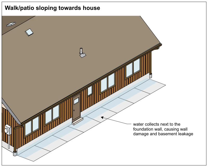 1929.5
Walk/patio sloping towards house
· p. 347
An oblique view shows a house with a jointed paved walk or patio running directly alongside its foundation wall. The paving slopes toward the house rather than away from it. Blue shading along the wall represents water collecting at the paving-to-foundation junction. The callout identifies foundation wall damage and basement leakage as consequences of this improper drainage.
Surface Water Control And Landscaping ·Retaining Wallsp. 348
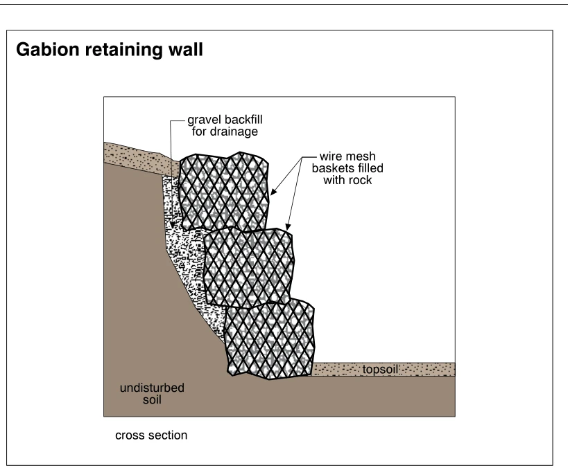 1930
1930Gabion retaining wall
· p. 348
The illustration shows a cross section of a gabion retaining wall supporting a change in ground elevation. Three tiers of rock-filled wire mesh baskets are stacked with each upper tier set back toward the retained soil. Gravel backfill lies between the baskets and the undisturbed soil and is identified as providing drainage. Topsoil is shown at the ground surface, including the lower grade in front of the wall. No failure or improper installation is depicted.
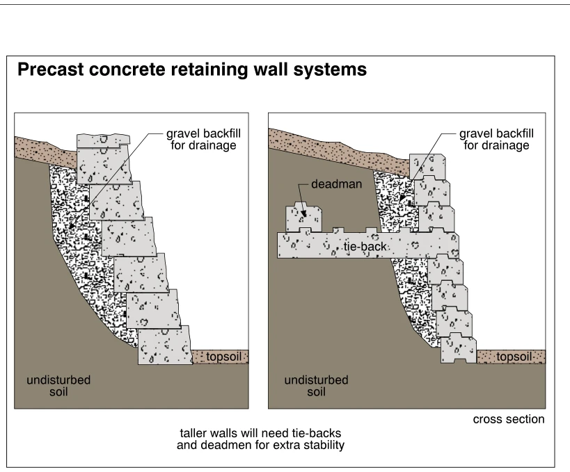 1931
1931Precast concrete retaining wall systems
· p. 348
Two cross sections illustrate precast concrete retaining wall systems supporting soil at different elevations. The left wall consists of stacked concrete units stepped back toward the retained soil, with gravel drainage backfill behind the wall. The right wall uses interlocking concrete units and a horizontal tie-back connected to a buried deadman in the retained soil. Both sections identify undisturbed soil and topsoil at the lower grade. An annotation states that taller walls need tie-backs and deadmen for extra stability.
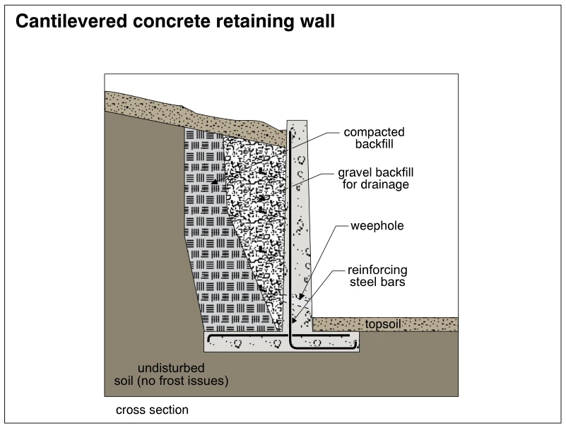 1932
1932Cantilevered concrete retaining wall
· p. 348
The cross section shows a reinforced concrete cantilever retaining wall holding back higher ground on one side. Its vertical stem connects to a horizontal footing extending beneath both the retained soil and the lower ground. Reinforcing steel bars extend down the stem and bend into the footing. Gravel backfill immediately behind the wall provides drainage to a weephole near the lower portion of the stem, with compacted backfill farther behind it. The footing rests on undisturbed soil labeled as having no frost issues, and topsoil covers the lower ground.
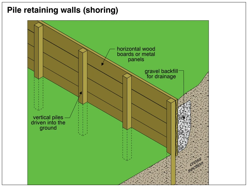 1933
1933Pile retaining walls (shoring)
· p. 348
The illustration shows a shoring-type retaining wall with horizontal wood boards or metal panels supported by vertical piles. The piles extend below the lower ground surface, with dashed outlines indicating their buried portions. Higher ground is retained behind the horizontal members. A cutaway at the end of the wall shows gravel backfill immediately behind the wall for drainage and the surrounding soil in cross section.
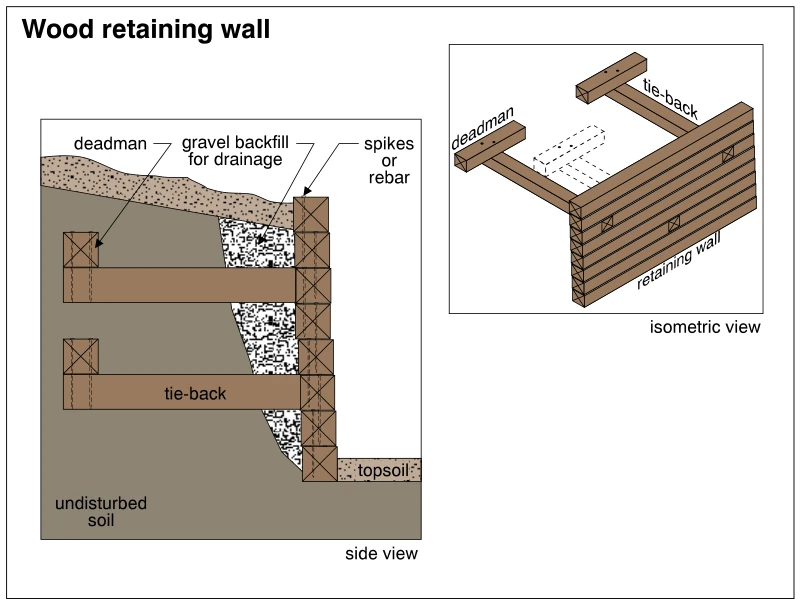 1934
1934Wood retaining wall
· p. 348
The illustration shows side and isometric views of a retaining wall built from stacked horizontal wood timbers. Tie-back timbers extend into the retained soil and connect to transverse deadman anchors behind the wall. Spikes or rebar fasten the wall timbers together, and gravel backfill directly behind the wall provides drainage. The side view shows the wall embedded in undisturbed soil with topsoil at the lower grade, while the isometric view illustrates the arrangement of the tie-backs and deadmen.
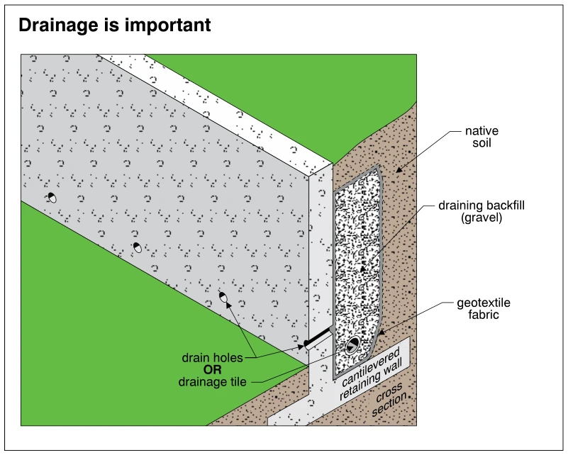 1935
1935Drainage is important
· p. 348
The illustration shows a concrete cantilevered retaining wall with a cutaway exposing drainage provisions behind the wall. Gravel drainage backfill separates the wall from the retained native soil, with geotextile fabric at the gravel-to-soil interface. Drain holes through the wall or drainage tile at the base of the backfill provide alternative routes for water to escape. The cross section also shows the wall stem extending down to its footing.
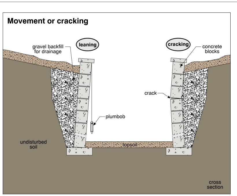 1936
1936Movement or cracking
· p. 349
The cross section depicts two concrete-block retaining walls supporting higher soil on either side of a lower ground area. Both walls have cap units, base footings, and gravel drainage backfill between the blocks and undisturbed soil. The left wall leans away from the retained soil, with a suspended plumb bob providing a vertical reference. The right wall bends inward toward the lower area and has an open horizontal crack at a block joint. Topsoil is shown across the lower area and above the retained soil.
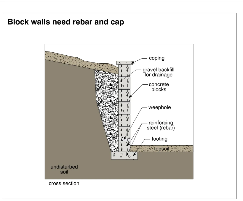 1937
1937Block walls needs rebar and cap
· p. 349
The illustration shows a cross section of a concrete block retaining wall supporting a higher soil level on one side. The wall has a coping cap, reinforcing steel, and a widened footing set below the lower ground level in undisturbed soil. Gravel backfill lies between the retained soil and the wall, and a weephole provides a drainage outlet near the base. The drawing depicts reinforcement, capping, and drainage provisions for a block retaining wall.
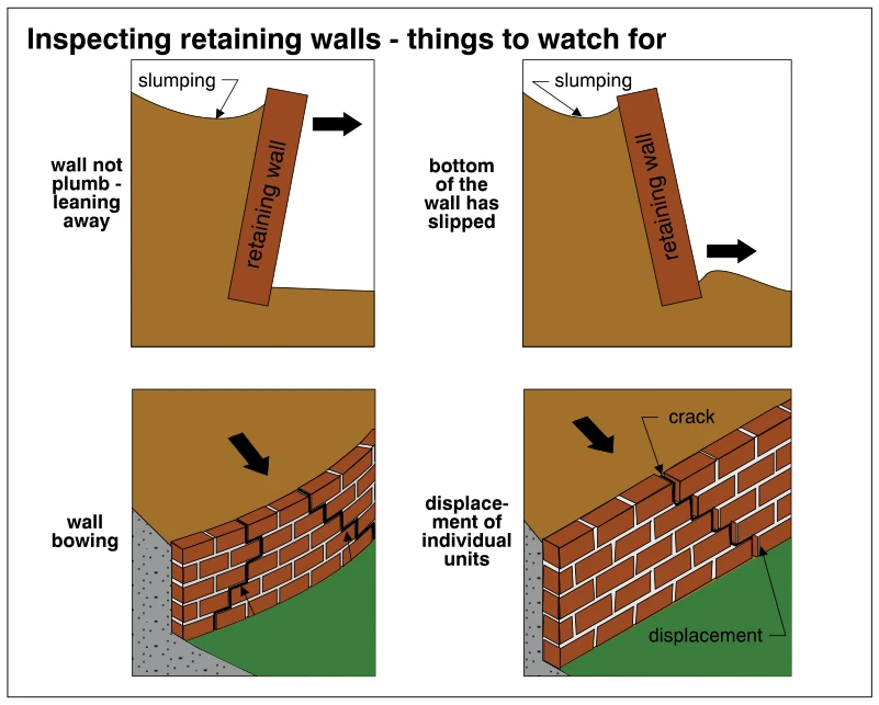 1938
1938Inspecting retaining walls - things to watch for
· p. 349
Four diagrams illustrate retaining-wall distress conditions. The upper-left section shows a wall leaning away from the retained soil, with slumping at the soil surface behind it. The upper-right section shows the bottom of a wall slipping outward, also accompanied by soil slumping. The lower-left view shows a masonry retaining wall bowing outward with separation between units. The lower-right view shows cracking and displacement of individual masonry units.
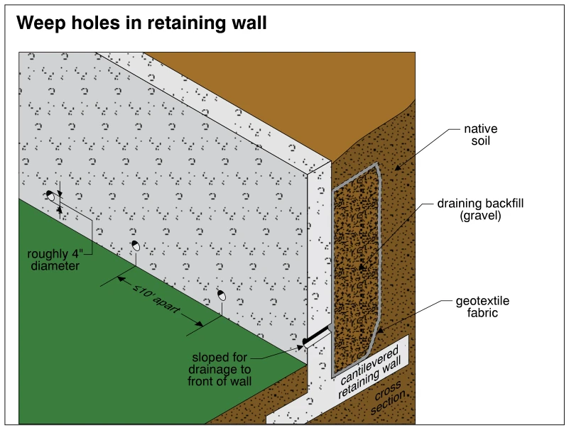 1939
1939Weep holes in retaining wall
· p. 349
The illustration shows a concrete cantilevered retaining wall with weep holes near its base and a cutaway exposing the drainage assembly behind it. The holes are labeled roughly 4 inches in diameter and spaced no more than 10 feet apart. A section through one hole shows it sloped to drain toward the front of the wall. Gravel drainage backfill sits behind the wall, with geotextile fabric separating it from the native soil.